127728026-binder-del-alumno.pdf
This document was uploaded by user and they confirmed that they have the permission to share it. If you are author or own the copyright of this book, please report to us by using this DMCA report form. Report DMCA
Overview
Download & View 127728026-binder-del-alumno.pdf as PDF for free.
More details
- Words: 4,534
- Pages: 227
Loading documents preview...
Subject
Content
Tab
Boomer 281/282 DC15
Introduction
1-4
Safety
5-22
Component location
23-34
Valves location
35-50
Daily checks
51-72
Operators platform
73-82
Traction
83-96
24V
97-106
Positioning
107-134
Electrical system
135-152
Air & Water system
153-162
Drilling
163-194
Telescopic feed
195-198
Cut hole
199-204
Swellex
205-223
Options
Training
Introduction
1 of 223 1
2 of 223
Introduction Teacher name: ____________________ Training hours 08,00 – 16,00 Tea / coffee brakes to be discussed 10,00 / 14,00 Lunch time to be discussed 12,00 Smoke brakes to be negotiated No smoking in Lecture room No Phone calls during lecture No computers during lecture Written check questions after each section Written exam after training Practical 3 of 223 2
4 of 223
Safety
1
5 of 223
6 of 223
Safety Knowledge target for this section You will after this section know safety features: Signs and symbols (warnings), Risk area of the rig, warning signals, emergency stops, fire fighting equipment
Content Safety Component Location Daily Checks Driving
2
Positioning Drilling Options
7 of 223
Safety References in documentation Safety Manual
3
8 of 223
Safety Content (Boomer 280-Series) Always read the safety instructions Location of Ansul and Fire extinguishers Emergency stop ”Beacon” Risk areas
4
9 of 223
Safety Fire fighting - ANSUL System A – Activator B – Nozzles C – Fire Extinguisher D – Propellant cartridge
5
10 of 223
Safety Fire fighting - ANSUL Activators
6
11 of 223
Safety ANSUL Activators
Check fire (option)
Ansul
7
12 of 223
Safety Fire extinguisher
8
13 of 223
Safety Emergency Stop
Emergency stop button
Indicator light
9
14 of 223
Safety Audio and visual alarms Horn button
Strobe
10
15 of 223
Safety Risk Areas during tramming and drilling
11
16 of 223
Safety Warning The manuals contain warnings. The warnings are in boxes and contain a safety message preceded by a warning symbol and a signal Different degrees of warnings – Danger – Warning – Caution
12
17 of 223
Safety Signs
13
18 of 223
Safety Signs
14
19 of 223
Safety Rig Stability
15
20 of 223
Safety Knowledge target for this section Be aware of: – The different signs and symbols (warnings) – Risk area of the rig when tramming – What kinds of warning signals the rig is equipped with – Functionality of the emergency stops – Different fire fighting equipment
16
21 of 223
22 of 223
Component location B281/B282-DC15
1
23 of 223
24 of 223
Component Location Knowledge target for this section Get a general knowledge of where the major component on the rig is located
Content Safety Component Location Daily Checks Driving
2
Positioning Drilling Options
25 of 223
Component Location References in documentation Operators Instructions – Component Locations
3
26 of 223
Component Location Main Components Protection roof Feed
Rock Drill
Electrical Cabinet Cable reel
Boom Rear Jacks Front Jacks
4
27 of 223
Component Location Right Rear Diesel engine air filter Ansul cartridge and powder container
Water reel
El.motor and pumps for boom 2 Rear Jacks 5
28 of 223
Component Location Right Rear
6
Hydraulic oil – Electric filling pump
29 of 223
Component Location Left Electrical cabinet Cable reel
ECL Lubrication tank
El. motor and pumps for boom 1
7
30 of 223
Component Location Behind Water Reel Water pump
Water inlet strainer
8
31 of 223
Component Location Inside Water Reel ISO switch Battery
Main fuse
9
32 of 223
Component Location Knowledge target for this section Be aware of: – The major components on the rig eg. Boom, cable reel, Pumps
If the rig is available: – Have walked around the rig and seen the components
10
33 of 223
34 of 223
Valves Location B282-DC15
1
35 of 223
36 of 223
Valves Location Knowledge target for this section Be aware of the different adjustment valves on the drill rig
Content Safety Component Location Daily Checks Driving
2
Positioning Drilling Options
37 of 223
Valves Locations References in documentation Maintenance Instructions – Component Locations
3
38 of 223
Valves Location VB 1 block
CT4
CT5 CT2 CT1 CT3/ Y156
4
39 of 223
Valves Location Valve V10 and V11 Percussion Pressure
V11 Percussion Pressure full drilling V10 Percussion Pressure Collaring
5
40 of 223
Valves Location V3a Rotation Speed V3a
6
41 of 223
Valves Location V3a Rotation Speed (Reaming)
V3a
7
42 of 223
Valves Location Vdp Damper Pressure
Vdp
8
43 of 223
Valves Location Vfm Maximum Feed Pressure
Vfm
9
44 of 223
Valves Location Vfl-Collaring / Vfh-full drilling pressure Vfh Vfl
10
45 of 223
Valves Location RPCF Regular/Reaming V1a (Regular)
11
V1b(Reaming)
46 of 223
Valves Location Vaj Anti jamming, feed return movement
Vaj
12
47 of 223
Valves Location V8/V17 Telescopic feed pressure difference and max feed return V17 V8
13
48 of 223
Valves Location V6 Feed pressure full drilling (Reaming)
V6
14
49 of 223
Valves Location Knowledge target for this section Be aware of: – Where the adjustment valves are located and their function
If the rig is available: – Have walked around the rig and seen the components
15
50 of 223
Daily checks
Inspections points
1
51 of 223
52 of 223
Daily Checks Knowledge target for this section Be aware of the daily checks, understand the importance of cleaning between shifts
Content Safety Component Location Daily Checks Driving
2
Positioning Drilling Options
53 of 223
Daily Checks References in documentation Maintenance schedules rig – Every 10 Percussion hour – Every 10 Diesel hour
Maintenance instructions rock drill Operation manual diesel engine – Maintenance Schedule
3
54 of 223
Daily Checks Purpose of daily checks Detect faults at an early stage Prevent costly secondary damage Prevent breakdowns Prevent personal injury
4
55 of 223
Daily Checks Cleaning – Between shifts To be able to see wear To be able to see damages
5
56 of 223
Daily Checks What to check for Check safety devices Check hoses and cables Check oil levels Check the lubrication points Keep your eyes open for possible leakage and wear Pay attention to any faults in the function of the controls
6
57 of 223
Inspections Points Emergency stop devices Control objects – Emergency stop devices
Action – Check the function of all the emergency stops on the rig
7
58 of 223
Inspections Points Fire extinguishers
0
0
OK
OK
Control objects – Fire extinguishers
Action – Make sure the indicator is in the green zone
1250 0098 88
– Check that none of the seals are broken and that service has been carried out within the prescribed time – Check that the fire extinguisher and its holder are not damaged
8
59 of 223
Inspection Points Check/Service points on feed
9
CHECK POINTS
SERVICE POINTS
•Hoses, tension and wear •Hose drum •Damages & oil leaks •Tension of ropes •Cradle and Feed retainers •Wear strips & Slides •Drill Steel Bushings •Centre drill steel support •Limit switch function •Rock drill attachment
•Tightening of bolts •Grease all lub. Points •Torque the tension bushing on feed cylinder •Wear strips & Slides •Ropes •Drill steel bushings •Bearings, pulley wheel & hose drum
60 of 223
Inspection Points Feed Control objects – Guide rails and slide pieces
Action – Check for wear on slide pieces and slide rails. Adjust if necessary
10
61 of 223
Inspection Points During Drilling Hyd. oil temp Water pressure Hydraulic pressures – Feed – Rotation – Percussion Lubrication pressure Return filters Hour meter Leakages Broken or damaged hoses
11
62 of 223
Inspection Points Check/Service points on the boom
12
CHECK POINTS
SERVICE POINTS
•Hoses, tension and wear •Damages & oil leaks •Drill Steel Bushings
•Tightening of bolts •Grease all lub. Points
63 of 223
Inspection Points Rock Drill Lubrication Air Lubrication oil Front Bushing Flushing seals Drill Collaring Accumulators Pressure and flow Pressure and frequency Check clearance No leaks Always on the shank
13
64 of 223
Inspections points Rock Drill Control objects – Rock drill accumulator charge pressure
Action – Press in the pin on the test valve. If the accumulator is charged, the pin will stick out by 4.5 mm and give a firm resistance when pressed in
14
65 of 223
Inspections points Rock drill cradle Control objects – Machine cradle
Action – If necessary, adjust the cradle to the correct height and centre directly on the beam
Clearance 5-7 mm
15
66 of 223
Inspections points Hydraulic system Control objects – Hydraulic oil level
Action – Top up if necessary
16
67 of 223
Inspections points Compressor Control objects – Oil reservoir
Action – Check the oil level in the oil reservoir (See instruction on how to check)
17
68 of 223
Inspections points Water system Control objects – Water inlet strainer
Action – Clean by opening blue valve
18
69 of 223
Inspections points Fire fighting system ANSUL Control objects – Nozzles/Hoses – Powder container
Action – Check that nozzles are clean and the protective caps are fitted and tight – Check that there is no damage to the powder container
19
70 of 223
Inspections points Diesel Engine oil level Control objects – Engine oil level
Action
Oil stick
– Top up if necessary
Oil fill
20
71 of 223
Daily checks Knowledge target for this section Be aware of: – The daily checks, what to check
Know: – The importance of performing daily checks – The importance of cleaning the rig between shifts
21
72 of 223
Operators platform B280-DC15
1
73 of 223
74 of 223
Operators platform Knowledge target for this section Know the functionality of the controls for driving, brake test, driving
Content Safety Component Location Daily Checks Driving
2
Positioning Drilling Options
75 of 223
Daily inspections References in documentation Operators Manual – Controls
3
76 of 223
Operators platform Drivers seat Instrument panel Levers for roof Levers for jacks Levers for diesel positioning
4
77 of 223
Operators platform Drilling and Positioning panel
5
78 of 223
Operators platform Instrument panel
T2 – Ignition key T4 – Parking brake T5 – Drilling lights T6 – Tramming lights T8 – Lamp test T10 – Gear lever T12 – Horn T16 – Park brake test button P1 – Hour meter for engine P2 – Fuel gauge 6
79 of 223
H11 – Parking brake H12 – Brake pressure H13 – Engine temp H14 – Hydraulic oil level H15 – Transmission H16 – Engine lubrication oil pressure H17 – Suction filter H18 – Battery charging H20 – Preheat indicator
Operators platform Brake test – Parking brake 1. Make sure that the parking brake is applied 2. Start the diesel engine and engage 2nd gear 3. Gradually increase engine rpm to maximum 4. Check the rig for movement. If the rig moves the brakes must be adjusted without delay – Note Do not continue this check for longer than 4 seconds at most
7
80 of 223
Operators platform Brake test – Service brakes 1. Start the diesel engine 2. Depress the brake pedal and hold it down 3. Release the parking brake 4. Engage 2nd gear 5. Gradually increase engine rpm to maximum 6. Check the rig for movement. If the rig moves the brakes must be adjusted without delay – Note Do not continue this check for longer than 4 seconds at most
8
81 of 223
Operators platform Knowledge target for this section Know the functionality of the controls for driving – – – –
Instrument panel Drill panel Boom panel Levers for jacks/roof
Know how to: – Perform parking brake test – Perform service brake test – Start the rig
Know the basics of driving the rig – Driving forward/backward – Turning – Gear selecting
9
82 of 223
Traction B282 DC15
1
83 of 223
84 of 223
Traction Knowledge target for this section Understand the hydraulics for brake and steering
Content Safety Component Location Daily Checks Driving
2
Positioning Drilling Options
85 of 223
Daily inspections References in documentation Diagrams and Drawings – Hydraulics
3
86 of 223
Components
5 6
4
2 3
1 4
87 of 223
Starting the system
5
88 of 223
Applying the brakes
6
89 of 223
Releasing the brakes
7
90 of 223
Park brake
8
91 of 223
Releasing Park brake
9
92 of 223
Activating Park brake
10
93 of 223
Steering
11
94 of 223
Traction Knowledge target for this section Be aware of: – The components in the brake and steering circuit – How the circuit is started hydraulically – How the brake and steering circuit works
12
95 of 223
96 of 223
Boomer
24V
1
97 of 223
98 of 223
Boomer 24V Knowledge target for this section Know how the 24 V system is built up
Content Safety Component Location Daily Checks Driving
2
Positioning Drilling Options
99 of 223
Daily inspections References in documentation Diagrams and Drawings – Electrics
3
100 of 223
Boomer 24V Main Switch Main switch
4
101 of 223
Power on
5
102 of 223
Ignition sequence
6
103 of 223
Interlock brake valve circuit
7
104 of 223
Cable reel 3 laps left
8
105 of 223
Boomer 24V Knowledge target for this section Be aware of: – What happens in the 24V circuit when the main switch is turned on – What happens in the circuit when the ignition key is turned – How the interlock brake valve circuit works – What happens when there are only three laps left on the cable reel
9
106 of 223
Positioning
1
107 of 223
108 of 223
Positioning Knowledge target for this section Controls for positioning, hydraulics for positioning
Content Safety Component Location Daily Checks Driving
2
Positioning Drilling Options
109 of 223
Positioning References in documentation Diagrams and Drawings – Hydraulics
Operators Instructions – Controls
3
110 of 223
Positioning Positioning panel Feed look out Feed rotation
Boom extension Feed extension Boom positioning
Anti parallel button
4
111 of 223
Positioning Overview of boom cylinders
5
K – Feed rotation
Z - Lock – out
FE – Feed ext
B – Boom ext
A1 – Boom cyl. rear left
A2 – Boom cyl. rear right
E1 – Boom cyl. front left
E2 – Boom cyl. front right
E1 FE
E2
B
Z K A1
112 of 223
A2
Positioning Levers for jacks and roof Left roof cyl
Right front jack Right slide
Right roof cyl
Rear jacks Left slide Left front jack
6
113 of 223
Positioning Levers for reels and diesel positioning 1/2 Diesel positioning Cable reel Hose reel
7
114 of 223
Positioning Levers for reels and diesel positioning 2/2 Cable reel override button Warning light for 3 laps left
8
115 of 223
Positioning Rear Controls for Reels Water reel Cable reel
9
116 of 223
Positioning Components
10
117 of 223
Positioning Diagram legend Red – pressure Blue – tank/return Green – pilot pressure (40bar) Yellow – other pilotpressure
11
118 of 223
Positioning Raising the Boom 1/2
12
119 of 223
Positioning Raising the Boom 2/2
13
120 of 223
Positioning Lowering the boom 1/2
1250 0060 05
14
121 of 223
Positioning Lowering the boom 2/2
15
122 of 223
Positioning Moving the boom to the right 1/2
1250 0060 05
16
123 of 223
Positioning Moving the boom to the right 2/2
17
124 of 223
Positioning Moving the boom to the left 1/2
1250 0060 05
18
125 of 223
Positioning Moving the boom to the left 2/2
19
126 of 223
Positioning Using the anti-parallel system feed swing 1/2
1250 0065 20
20
127 of 223
Positioning Using the anti-parallel system feed swing 2/2
21
128 of 223
Positioning Using the anti-parallel system feed lift 1/2
1250 0065 20
22
129 of 223
Positioning Using the anti-parallel system feed lift 2/2
23
130 of 223
Positioning Movement of the feed
24
131 of 223
Positioning Jacks
25
132 of 223
Positioning Roof
26
133 of 223
Positioning Knowledge target for this section Be aware of: – The controls for positioning, which lever does what and where are they located
Be able to describe the following – How the positioning works hydraulically – Which are the main components – Boom positioning valves / functions
27
134 of 223
Electrical system
1
135 of 223
136 of 223
Electrical System Knowledge target for this section Be aware of the components in the electrical system
Content Safety Component Location Daily Checks Driving
2
Positioning Drilling Options
137 of 223
Positioning References in documentation Diagrams and Drawings – Electrics
Operators Instructions – Electrics system
3
138 of 223
Electrical System Warning lights on A-cabinet
4
Phase sequence fault
Low hyd. Oil level
High hyd. Oil temp
Motor overload
Return oil filter indicator
Power on
139 of 223
Electrical System Switches on A-cabinet Diode test Emergency stop
Lamp test
Motor switch, motor nr 2 Motor switch, motor nr 1
5
140 of 223
Electrical System Main Switch
6
141 of 223
Electrical System The right side of the A-Cabinet V33 Diode bridge for check lights
T50 Internal Transformer
7
142 of 223
K29
Electrical System The right side of the A-Cabinet
K64 Start relay pump1
K164
K74
Emergency stop power supply relay
Start relay pump1
K163
K28
24V Power Supply changer
Low hydraulic oil level relay
K31 24V Power supply changer
K128 Emergency stop relay
K30 Compressor timer relay
8
143 of 223
Electrical System The right side of the A-Cabinet K132 Water Pump relay K127 Compressor relay
9
144 of 223
Electrical System The right side of the A-Cabinet F131
F18
F20
Water Pump Fuse
Fuse 3 phase outlet
Back-Up Fuse
F19 F126 Compressor Fuse
10
145 of 223
Control Transformer Fuse
Electrical System The right side of the A-Cabinet
F22 F17
F66
Battery Charger
F77
F91
Fuse Control 110V AC Pump1 Fuse descriptions
F76 Fuse Control 110V AC Pump1
11
146 of 223
F48
F67
F49
Headlight 24V AC
Control 24V DC
Working light 220V AC
Electrical System The right side of the A-Cabinet S13 Select Measuring
12
147 of 223
P12
K10
Voltmeter/ Ampmeter
Earth-fault relay
Electrical System The right side of the A-Cabinet P66 Hour meter Rock Drill 1
P76 Hour meter Rock Drill 1
ECL Rock Drill Lubrication
K26 Phase rotation F6 Fuse relay
K133 Water pump time relay
K32
13
148 of 223
Electrical System ECL System
Diod to indicate lubrication time T2 Lubrication Dosage T1 Lubrication pulse time
Indicates that power is on
14
149 of 223
Electrical System The Left side of the A-Cabinet U158 Battery charger
U180 Rectifier
X1 3 Phase outlet
15
150 of 223
Electrical System Knowledge target for this section Be aware of: – The different components in the electrical system – Where the components are located
If the rig is available: – Have walked around the rig and seen the components
16
151 of 223
152 of 223
Air & Water system B281/282-DC15
1
153 of 223
154 of 223
Air & Water Knowledge target for this section Understand the air and water system
Content Safety Component Location Daily Checks Driving
2
Positioning Drilling Options
155 of 223
Positioning References in documentation Diagrams and Drawings – Air
3
156 of 223
Air & water schedule Valves for rock drill lubrication (Y106, Y107) Compressor
Watermist Water pump and flow guard B141
Watermist
4
157 of 223
Air & water schedule Y106 Y107
5
158 of 223
Air & water schedule
B141
6
159 of 223
Air blowing
Air 7
160 of 223
Water (Flushing)
Water 8
161 of 223
Air & Water Knowledge target for this section Be aware of: – How the air and water circuits work
9
162 of 223
Drilling B281/282-DC15
1
163 of 223
164 of 223
Drilling Knowledge target for this section Controls and gauges for drilling, drilling circuits, components
Content Safety Component Location Daily Checks Driving
2
Positioning Drilling Options
165 of 223
Drilling Drilling Panel 1/2
Percussion pressure Feed pressure
Rotation pressure Pump on
ECL Collaring Full drilling
3
166 of 223
Drilling Drilling Panel 2/2
Pump off Water
Percussion Feed movement
Rotation
Hole size (option)
4
167 of 223
Drilling Manometers Return oil filter
Air
Water
Damper rock drill 2
Damper rock drill 1
5
168 of 223
Drilling Check points during drilling Hyd. oil temp Water pressure Hydraulic pressures – Feed – Rotation – Percussion Lubrication pressure Return filters Hour meter Leakages Broken or damaged hoses
6
169 of 223
Drilling Power packs DCS 12 1-boom
P1
P2
DCS 12 2-boom, DCS 15/18 all rigs
P1 P2
P3
P1 – Main pump (positioning and percussion). (damper only on 1 boom) P2 – Rotation pump P3 – Damper pump (only 2-boom), water pump (only 1-boom) 7
170 of 223
Drilling Hydraulic diagram legend Red – pressure Blue – tank/return Green – pilot pressure (50bar) Yellow – other pilot pressure
8
171 of 223
Drilling Main Components 1/2 Rotation Unit
Rock Drill
Feed
RPCF Valve Low/High Feed Pressure Regulator Feed Pressure Control Valve
Button for loosening of drill bit
Antijamming valve
Rotation Lever
9
Percussion Lever
Feed Movement Lever
172 of 223
Drilling Main Components 2/2 Limit switch
VB1
Main pump
ECL Pump
Flow regulation for damper
Rotation pump Damper pump
Flow regulation for rotation
10
173 of 223
Drilling Main pump start – The first 8 seconds To tank
Step 1
Percussion/Rotation
Power the water pump
Rotation 11
174 of 223
Drilling Main pump start – After 8 seconds Step 2
12
175 of 223
Drilling Rotation 1/2
13
176 of 223
Drilling Rotation 2/2
14
177 of 223
Drilling Feed forward 1/2
15
178 of 223
Drilling Feed forward 2/2
16
179 of 223
Drilling Feed Reverse
17
180 of 223
Drilling Drill Sequence – Collaring 1/2
40-50 bar
230 bar
18
181 of 223
Drilling Drill Sequence – Collaring 2/2
V11
19
182 of 223
Drilling Drill Sequence – Full Drilling 1/2 image description
65-100 bar
20
183 of 223
Drilling Drill Sequence – Full Drilling 1/2
V12
21
184 of 223
Drilling Limit Switch (Black Jack) 1/2
22
185 of 223
Drilling Limit Switch (Black Jack) 2/2
23
186 of 223
Drilling Drilling Protection Systems RPCF (Rotation Pressure Control Feed) FPCI (Feed Pressure Control Impact) Anti Jamming (Feed reverse with full system pressure)
24
187 of 223
Drilling Drilling Protection System 1 – RPCF 1/2 50-60 bar
50 bar
Pressure limit set to appr. 20 bar above normal rotation Pressure
25
188 of 223
Drilling Drilling Protection System 1 – RPCF 2/2
Pressure increases
Pressure increases
26
189 of 223
Drilling Drilling Protection System 2 – FPCI (Anti jamming) 1/2
Pressure increases
Pressure increases
27
190 of 223
Drilling Drilling Protection System 2 – FPCI (Anti jamming) 2/2
28
191 of 223
Drilling Loosening the drill bit 1/2
29
192 of 223
Drilling Loosening the drill bit 2/2
30
193 of 223
Drilling Knowledge target for this section Be aware of: – The different controls for drilling – The checkpoints during drilling – Powerpack setup – Hydraulic circuits for drilling – Drilling protection RPCF, Anti-Jamming and FPCI
31
194 of 223
Telescopic feed
1250 0064 09
1
195 of 223
196 of 223
Telescopic Feed 31 33
2
197 of 223
198 of 223
Cut hole
1
199 of 223
200 of 223
Cut hole Knowledge target for this section Understand the function of the cut hole option
Content Safety Component Location Daily Checks Driving
2
Positioning Drilling Options
201 of 223
Components
Control valve for small hole/cut hole feed pressure
V1b
V6
V3A
Cut hole lever
3
202 of 223
Cut hole ~60 bar
4
203 of 223
Cut hole Knowledge target for this section Be aware of: – How the Cut hole option does and how it works
5
204 of 223
Swellex
Boomer
205 of 223
206 of 223
Swellex Content Manufacturing General description Installation procedure Technical features Range of products Accesories
207 of 223
Swellex Manufacturing
208 of 223
Swellex Expansion principles SWELLEX before expansion
Face Plate
Inlet Hole SWELLEX Installed In the hole
B A >> B
High water
Expanded SWELLEX in the hole
SWELLEX after expansion
Pressure 300 bar After expansion air pressure force water out of the inlet hole
209 of 223
Swellex Immediate full column support
210 of 223
Swellex Installation methods Manual bolting Semi-mechanized bolting Boomer + Service platform Fully Mechanized BOLTEC
211 of 223
Swellex Installation sequence
1
Drilling
2
Insertion
3
Expansion
4
Pumps automatically stops
Atlas Copco
Atlas Copco
212 of 223
Swellex
0,5 m
Features in the hole
Allows major shear movements Swellex bridges gaps in the rock
Swellex follows all the irregularituis in the hole In hard rock, 50 cm inflated profile develop 100KN friction
Swellex Net washer for screening
213 of 223
Swellex Range
Mn12 Swellex
Mn24 Swellex
Mn16 Swellex
TOP BOLT
Coated Swellex
BOTTOM BOLT
3m
Connectable Swellex
INTERMEDIATE BOLTS 214 of 223
Swellex Dimensions Standard&Super Mn12 Swellex
Mn24 Swellex 36 mm
25,5 mm 3 mm
2 mm
215 of 223
Swellex Recommended hole diameters
Initial Profile
Min Hole diameter
Mn12 Swellex
26 mm
32 mm
39 mm
Mn24 Swellex
36 mm
43 mm
52 mm
Mn16 Swellex
36 mm
43 mm
52 mm
216 of 223
Max hole diameter
Swellex Equipement
PSP 240 / 300 HYDRAULIC pump with manometer
Pull test equipment
Special adapter for Swellex lower bushing
217 of 223
Swellex Face plate Adjustable faceplate for optimal load distribution, even in case of angled hole direction
218 of 223
Swellex Net washer
219 of 223
Swellex
Strainer
Swellex pump H1
(100µ = 0,1mm = 0.003936996 Inch)
Valve Pressure regulator
Pump unit 220 of 223
Swellex Swellex pump H1 Water Connection
Manometer water pressure
Swellex arm water Oil pressure in
Drain
Oil pressure return 221 of 223
Swellex Swellex pump H1 - Specification
Water pressure, water consumption and water temperature - Water pressure in 2-20 bar - Max. water pressure 350 bar - Max. water consumption 17 L/min - Max water temperature 70°C Hydraulic pressure and flow rates - Min. hydraulic pressure 120 bar - Max. hydraulic pressure 210 bar - Flow 40 L/min
222 of 223
Swellex Swellex pump H1 – Setting pressure 300 Bar Bolt – Setting 300 bar to 305 bar
240 Bar Bolt – Setting 240 bar to 245 bar
223 of 223
More Documents from "Cesar Quintanilla"

127728026-binder-del-alumno.pdf
January 2021 0
Para Caminos 2.docx
January 2021 3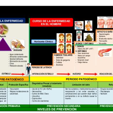
Tifoidea Esquema
January 2021 2
Bombeo En Pavimentos
February 2021 0
