Abb Pp30012hs(abbn)5a
This document was uploaded by user and they confirmed that they have the permission to share it. If you are author or own the copyright of this book, please report to us by using this DMCA report form. Report DMCA
Overview
Download & View Abb Pp30012hs(abbn)5a as PDF for free.
More details
- Words: 544
- Pages: 4
Loading documents preview...
ABB Industry Oy
hint7.doc
ACS 600 hints
VSD Products, Medium AC Drives Dept.
Date
Prepared
Check./Appr.
Revision
TJX
22.05.97
Ere Jääskeläinen
Kjell Ingman
A
7.0
Page
1/4
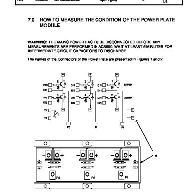
HOW TO MEASURE THE CONDITION OF THE POWER PLATE MODULE
WARNING: THE MAINS POWER HAS TO BE DISCONNECTED BEFORE ANY MEASUREMENTS ARE PERFORMED IN ACS600. WAIT AT LEAST 5 MINUTES FOR INTERMEDIATE CIRCUIT CAPACITORS TO DISCHARGE. The names of the Connectors of the Power Plate are presented in Figures 1 and 2
5
1
3
G13
G12
G11
E13
E12
E11
6
4
UPPER
2
G23
G22
G21
E23
E22
E21
LOWER
T1 T T2
P3
P2
P1
+
T1 G23
E23
G22
E22
G21
E21
E13
G13
E12
G12
E11
G11
T2
P3
Figure 1. LPP
P2
P1
-
*
ABB Industry Oy
hint7.doc
ACS 600 hints
VSD Products, Medium AC Drives Dept.
Date
Prepared
Check./Appr.
Revision
TJX
22.05.97
Ere Jääskeläinen
Kjell Ingman
A
5
3
1
G13
G1 2
G 11
E 13
E 12
E 11
6
4
UP P E R
2
G 23
G22
G 21
E 23
E 22
E 21
L OW E R
T1 T T2
P2
P3
P1
T1 G23
E 23
G22
E22
G21
E21
E13
G 13
E12
G12
E 11
G 11
T2
P3
Figure 2. MPP
P2
+ -
P1
*
Page
2/4
ABB Industry Oy
hint7.doc
ACS 600 hints
VSD Products, Medium AC Drives Dept.
Date
Prepared
Check./Appr.
Revision
TJX
22.05.97
Ere Jääskeläinen
Kjell Ingman
A
The following result should be observed if the Power Plate is undamaged.
7.1 Measuring the collector-emitter resistance of the IGBT Measurement is done with the multimeter in the “diode” selection. Plus-probe + + + P1 P2 P3
Minus-probe P1 P2 P3 -
Display OL OL OL OL OL OL
7.2 Measuring the diode of the IGBT Measurement is done with the multimeter in the “diode” selection. Plus-probe P1 P2 P3 -
Minus-probe + + + P1 P2 P3
Display ≈ 0.35V ≈ 0.35V ≈ 0.35V ≈ 0.35V ≈ 0.35V ≈ 0.35V
7.3 Measuring the gate of the IGBT Measurement is done with the multimeter in the “resistance” selection. Plus-probe G11 G21 G12 G22 G13 G23
Minus-probe E11 E21 E12 E22 E31 E23
Display OL (loading capacitance) OL (loading capacitance) OL (loading capacitance) OL (loading capacitance) OL (loading capacitance) OL (loading capacitance)
Page
3/4
ABB Industry Oy
hint7.doc
ACS 600 hints
VSD Products, Medium AC Drives Dept.
Date
Prepared
Check./Appr.
Revision
TJX
22.05.97
Ere Jääskeläinen
Kjell Ingman
A
Page
4/4
7.4 Measuring the thermistor of the Power Plate Measurement is done with the multimeter in the “resistance” selection. Plus-probe T1
Minus-probe T2
Display 10 kΩ (+/-10%)
Measurement has to be done when the Power Plate module is at room temperature.
7.5 Measurements against frame Measurement is done with the multimeter in the “resistance” selection. Plus-probe T1 T2 auxiliary + auxiliary P1 P2 P3
Minus-probe frame frame frame frame frame frame frame
Display OL OL OL OL OL OL OL
Auxiliary + and - are marked with * in pictures 1 and 2.
7.6 Measuring the emitter of the IGBT Measurement is done with the multimeter in the “resistance” selection. Plus-probe E11 E12 E13 E21 E22 E23
Minus-probe P1 P2 P3 -
Display ≈0Ω ≈0Ω ≈0Ω ≈0Ω ≈0Ω ≈0Ω
hint7.doc
ACS 600 hints
VSD Products, Medium AC Drives Dept.
Date
Prepared
Check./Appr.
Revision
TJX
22.05.97
Ere Jääskeläinen
Kjell Ingman
A
7.0
Page
1/4
HOW TO MEASURE THE CONDITION OF THE POWER PLATE MODULE
WARNING: THE MAINS POWER HAS TO BE DISCONNECTED BEFORE ANY MEASUREMENTS ARE PERFORMED IN ACS600. WAIT AT LEAST 5 MINUTES FOR INTERMEDIATE CIRCUIT CAPACITORS TO DISCHARGE. The names of the Connectors of the Power Plate are presented in Figures 1 and 2
5
1
3
G13
G12
G11
E13
E12
E11
6
4
UPPER
2
G23
G22
G21
E23
E22
E21
LOWER
T1 T T2
P3
P2
P1
+
T1 G23
E23
G22
E22
G21
E21
E13
G13
E12
G12
E11
G11
T2
P3
Figure 1. LPP
P2
P1
-
*
ABB Industry Oy
hint7.doc
ACS 600 hints
VSD Products, Medium AC Drives Dept.
Date
Prepared
Check./Appr.
Revision
TJX
22.05.97
Ere Jääskeläinen
Kjell Ingman
A
5
3
1
G13
G1 2
G 11
E 13
E 12
E 11
6
4
UP P E R
2
G 23
G22
G 21
E 23
E 22
E 21
L OW E R
T1 T T2
P2
P3
P1
T1 G23
E 23
G22
E22
G21
E21
E13
G 13
E12
G12
E 11
G 11
T2
P3
Figure 2. MPP
P2
+ -
P1
*
Page
2/4
ABB Industry Oy
hint7.doc
ACS 600 hints
VSD Products, Medium AC Drives Dept.
Date
Prepared
Check./Appr.
Revision
TJX
22.05.97
Ere Jääskeläinen
Kjell Ingman
A
The following result should be observed if the Power Plate is undamaged.
7.1 Measuring the collector-emitter resistance of the IGBT Measurement is done with the multimeter in the “diode” selection. Plus-probe + + + P1 P2 P3
Minus-probe P1 P2 P3 -
Display OL OL OL OL OL OL
7.2 Measuring the diode of the IGBT Measurement is done with the multimeter in the “diode” selection. Plus-probe P1 P2 P3 -
Minus-probe + + + P1 P2 P3
Display ≈ 0.35V ≈ 0.35V ≈ 0.35V ≈ 0.35V ≈ 0.35V ≈ 0.35V
7.3 Measuring the gate of the IGBT Measurement is done with the multimeter in the “resistance” selection. Plus-probe G11 G21 G12 G22 G13 G23
Minus-probe E11 E21 E12 E22 E31 E23
Display OL (loading capacitance) OL (loading capacitance) OL (loading capacitance) OL (loading capacitance) OL (loading capacitance) OL (loading capacitance)
Page
3/4
ABB Industry Oy
hint7.doc
ACS 600 hints
VSD Products, Medium AC Drives Dept.
Date
Prepared
Check./Appr.
Revision
TJX
22.05.97
Ere Jääskeläinen
Kjell Ingman
A
Page
4/4
7.4 Measuring the thermistor of the Power Plate Measurement is done with the multimeter in the “resistance” selection. Plus-probe T1
Minus-probe T2
Display 10 kΩ (+/-10%)
Measurement has to be done when the Power Plate module is at room temperature.
7.5 Measurements against frame Measurement is done with the multimeter in the “resistance” selection. Plus-probe T1 T2 auxiliary + auxiliary P1 P2 P3
Minus-probe frame frame frame frame frame frame frame
Display OL OL OL OL OL OL OL
Auxiliary + and - are marked with * in pictures 1 and 2.
7.6 Measuring the emitter of the IGBT Measurement is done with the multimeter in the “resistance” selection. Plus-probe E11 E12 E13 E21 E22 E23
Minus-probe P1 P2 P3 -
Display ≈0Ω ≈0Ω ≈0Ω ≈0Ω ≈0Ω ≈0Ω
Related Documents

Abb Antivirus
January 2021 0
Abb Transformers
March 2021 0
Abb Iec61850
January 2021 0
Abb Safelinkba2002pres.pdf
February 2021 0
Abb Gc
January 2021 2
Abb Sa.pdf
February 2021 1More Documents from "Jeteendra Sharma"