Api - 682.pdf
This document was uploaded by user and they confirmed that they have the permission to share it. If you are author or own the copyright of this book, please report to us by using this DMCA report form. Report DMCA
Overview
Download & View Api - 682.pdf as PDF for free.
More details
- Words: 22,469
- Pages: 53
Loading documents preview...
Rotating Equipment Specialist Training Program ®
Overview of API 682 / ISO 21049 and the Seal Requirements for API 610 and ASME B73
Footer1
Experience in Motion
Page 1
Rotating Equipment Specialist Training Program ®
This training module is part of the Rotating Equipment Specialist training program. Any questions concerning the RES program should be directed to Paul McMahan ([email protected]). Questions pertaining to the content of this module should be directed to your trainer or Michael Huebner ([email protected]). This module may not be distributed outside of Flowserve without written permission from Paul McMahon.
Copyright © 2005 Flowserve Corporation Revision 1.04 Prepared by Michael Huebner August 2005
Footer2
Experience in Motion
Page 2
Rotating Equipment Specialist Training Program ®
Table of Contents API 682 / ISO 21049 .............................................................................................................................. Introduction History of API 682 and ISO 21049 Scope of the Standard ............................................................................................................................ Key Concepts .......................................................................................................................................... Seal Types ............................................................................................................................................... Type A Type B Type C Rotating vs Stationary Flexible Element Seals Seal Arrangements and Orientation Codes ............................................................................................. CW - Contacting Wet CS - Containment Seal NC - Non-Contacting Arrangement 1 Arrangement 2 Arrangement 3 Seal Categories ....................................................................................................................................... Dimensions .............................................................................................................................................. Design Requirements ............................................................................................................................... Accessories ............................................................................................................................................. Inspection, Testing, and Preparation for Shipment .................................................................................. Liquid Seal Testing Containment Seal Testing Dual Gas Seal Testing Hydrostatic Testing of Glands Air Testing of Seal Assemblies Pump Manufacturer Seal Test Overview of Annexes ............................................................................................................................... Seal Selection Procedure ......................................................................................................................... Piping Plans ............................................................................................................................................. Plan 14 Plan 53A Plan 53B Plan 53C Plan 65 Plan 71 Plan 72 Plan 74 Plan 75 Plan 76 Data Sheet .............................................................................................................................................. Seal Code ............................................................................................................................................... Sealing Considerations in API 610 / ISO 13709 .................................................................................. API 610 Seventh Edition (Obsolete) API 610 Tenth Edition / ISO 13709 Sealing Considerations in ASME B73 .................................................................................................
Footer3
Experience in Motion
Page 3
4 6 7 8
10
15 17 18 25 29
35 35 38
43 43 44 49
Rotating Equipment Specialist Training Program ®
API 682 / ISO 21049 Introduction API-682 First Edition was really a landmark document in the field of mechanical sealing. The standard was not a simple technical document but rather a complete overview of mechanical sealing in the refinery environment. One of the most import aspects of this standard was that it was created by industry leaders in rotating equipment from the major refineries. These individuals recognized that many of the experienced engineers and maintenance personnel were retiring without documenting their knowledge. This standard was designed to capture some of this field experience. Rather than show every possible solution to an application, the Task Force decided to default a single proven solution. This solution would be the most commonly used approach used in industry. In addition to the default solution, alternates would be presented when they were technically acceptable. An alternate is technically equivalent to the default solution. The Task Force also realized that it would be impossible to cover every application on every piece of equipment used in a refinery. They focused the standard on addressing the most common applications, in common fluids, in common equipment. The standard does not address hazardous fluid such as HF acid or cover special equipment such as turbines or compressors. Still the standard covers the vast majority of application found in the refinery. The mission statement captures the intention of the standard. Breaking this down, we can see some of the major points:
“This standard is designed to default to the equipment types most commonly supplied that have a high probability of meeting the objective of a least three years of uninterrupted service while complying with emissions regulations.” Let’s break this into parts. This standard is designed to default (that is come up with a single solution) … to the equipment types most commonly supplied (not every sealing solution but only the most common ones that have proven to be successful in the field)… that have a high probability (not a guarantee but a high probability)… of meeting the objective of three years of uninterrupted service (the seal must be designed so it is capable of at least three years of service without adjustments, alterations, or refurbishment)… while complying with emissions regulations. This was the goal of the First Edition. Since the First Edition was officially published in 1994, it has become the highest selling API standard on mechanical equipment. It has been sold in over 25 countries and is universally recognized as THE standard for mechanical seals in the refinery industry.
Footer4
Experience in Motion
Page 4
Rotating Equipment Specialist Training Program ®
Due to the success of the First Edition, API recognized the need for a Second Edition. One of the driving forces was the knowledge that the standard was being used in industries outside of refineries. Companies were using API pumps in chemical and petrochemical facilities. In addition, refineries were also ANSI/ASME pumps for many general or low-duty services. In either case, it was difficult or impossible to apply the First Edition to these applications. Sealing technology has made great advancements since the release of the First Edition. Dual dry running seals and containment seals were now used commonly in refineries and chemical plants. New piping plans were developed to support these new seal types. There was confusion on how to designate these new seals, arrangements, and piping plans. While the First Edition had become a sort of “international standard”, it was written very much like an American standard. Many of the dimensions defaulted to US customary units. Most of the outside references were to US standards organizations like ASME or ANSI. This made the standard difficult to apply in many countries. All of these factors influenced the direction of the Second Edition. The goal was to continue with the objectives of the First Edition while expanding into new industries and capture new seal technology. This was done with the clear intention of having the standard issued as an ISO international standard. Due to the long lead times required for ISO document review and approval, the Task Force decided to release the Second Edition ahead of the formal ISO document release. This way users could begin using the standard years ahead of the ISO release.
During the ISO review process, member countries around the world are allowed to suggest changes, make comments, and identify corrections. This process can take several years. In addition ISO documents have strict requirements related to formatting and how “requirements” and “comments” are stated in the body of the text. During the review process, several changes were made resulting in reformatting the first several chapters. Many specific clauses were reworded to move requirements outs of the comments section. Many minor errors were corrected. The piping plan flowchart in Annex A was slightly modified. Most of the figures were redrawn to conform to ISO formatting styles. None of these changes resulted in any substantial technical modifications to the Second Edition. During the review process, there was also a suggestion to add a piping plan for detection of atmospheric leakage. This plan has been used for many years but did not have a designation. The collection of atmospheric side leakage (with it’s associated piping components and instrumentation) is now defined as Plan 65. This will be covered in a later Training Module. ISO 21049 was released in February of 2004. While the document is a little more polished than the Second Edition, the two are virtually identical in content. Any seal that was designed in accordance with our standards for API 682 seal design will also meet the requirements of ISO 21049.
Footer5
Experience in Motion
Page 5
Rotating Equipment Specialist Training Program ®
The release of an updated “682 standard” in the form of ISO 21049 left API in am awkward situation. There were now two standards that were very close but not identical. Which standard should the user invoke? Most importantly to API, would people stop using the Second Edition because they believed that ISO 21049 was the latest release? To solve this problem, API decided to release the Third Edition. This edition is identical in content to ISO 21049 – essentially a copy of ISO 21049 with an API cover on the front. In this way, both standard have the same requirements and it removes the confusion of which standard to use.
From Flowserve’s perspective, any seal that was designed in accordance with API 682 Second Edition design standards will fully meet the requirements of both ISO 21049 and API 682 Third Edition. All seals that were qualified in accordance with API 682 Second Edition are also qualified under the other two standards. The release ISO 21049 and API 682 Third Edition have little impact on our seal selection and design practices.
Scope of the Standard As stated earlier, the 682 Task Force did not intend this standard to cover every piece of rotating equipment in a refinery. It was intended to cover perhaps 90% of the sealed rotating equipment. The various editions have the following scopes. The First Edition used the term “Seal Size” throughout the standard. This lead to some confusion since different seal OEMs use different criteria for determining their commercial designation for a seal size. The Second Edition (and beyond) uses the shaft diameter which is unambiguous. With this cleared up, the First Edition was limited to seal sizes from 30mm to 120mm (1.50” to 4.50”). The Second Edition (and beyond) is applicable to shaft sizes from 20mm to 110mm (0.75” to 4.30”).
The First Edition had a temperature range from -40°C to 260°C (-40°F up to 500°F). The Second Edition greatly expanded this to -40°C to 400°C (-40°F to 750°F). The First Edition was used in pressures from 0 to 34.5 bar (0 to 515 PSIA) while the Second Edition is used from 0 to 42 bar (0 to 615 PSIA). The applicable process fluids are unchanged from the First to the Second Edition (and beyond). Footer6
Experience in Motion
Page 6
Rotating Equipment Specialist Training Program ®
The First Edition was written specifically to be used in API 610 8th edition pumps. API 610 was later adopted by ISO and designated as ISO 13709. The Second Edition (and beyond) still applies to the API 610/ISO 13709 pumps. It has also been expanded to include ANSI B73.1 and B73.2 seal chambers and ISO 3069 Frame C seal chambers. On the ANSI/ASME pumps notice that this applies only to the seal chambers (often called big bore boxes). This standard does not apply to seals designed to fit into the small stuffing boxes designed for packing.
Key Concepts One of the challenges the First Edition Task Force had was to standardize a number of concepts in the sealing industry. Up to this point, every OEM and user had developed their own methods and terminology when referring to seals. We will briefly cover some of these concepts now and they will be covered in more detail later in the training program. The First Edition introduced a “Definition of Terms” section to define key words. This has been continued and expanded in the “Terms and Definitions” section in the Second Editions. There are literally hundreds of different seals in use today. API 682 defines three basic seal types that are used in this standard. These definitions include design details as well as materials of construction. Seal arrangements define the number of seals, orientations of the seals to each other, and function of the seals. The First Edition allowed only three basic seal arrangements. The Second Edition expanded this greatly due to the addition of new seal types. Seal categories was a new concept introduced in the Second Edition. A seal category is a sub-specification that defines the seal, its use, its applicable pump type, and documentation requirements. While the First Edition did not cover the design of the component parts of a mechanical seal, it did address many specific design features. The Second Edition continued with the same requirements and adds additional design details for the new seal types. API-682 seals are designed to meet a minimum of three years of uninterrupted service. The question the Task Force faced was how the standard would give the end user the confidence level that these seals can achieve this goal. The answer was to qualify all seals in a well defined test program that, in some ways, simulated the operating conditions seen in a pump. This included defining the test medium, conditions, and documentation requirements. One of the most important aspects of seal applications is initially selecting the correct type of seal and piping plan. The First Edition introduced a structured selection process where the user followed a series of tables and flowcharts to arrive at a seal selection. The Second Edition expanded this concept with additional details to cover the new seal types and piping plans. Earlier we learned that 682 is designed to default to a single solution but that, if applicable, other alternatives would be offered. Where an alternate selection is available, it viewed as technically equivalent to the default selection. API 682 was the first document to address many of these key concepts. In doing so, it became more than a simple standard. It became a standard, a tutorial, and a textbook on mechanical seal applications.
Footer7
Experience in Motion
Page 7
Rotating Equipment Specialist Training Program ®
Seal Types Over the years, seal companies have released literally hundreds of seal designs and variations. Surprisingly, there has been very little effort to standardize seal designs, materials, dimensions, or even their interfaces into a pump. There are some German standards that define interface between component seals and pumps as well as some ANSI, API, and ISO efforts to define a standard seal chamber. Still, the design of seal chambers and mechanical seals has largely been in the domain of the OEMs. One of the challenges for the API 682 Task Force was to create standard seal types that would define the basic seal design, materials of construction, minimum installation envelope, and operating windows. A Seal Types is a basic description of the seal. Historically people used terms like spring pusher, bellows, multispring, single spring, rotating, and stationary to describe a seal. They would also add other design features such as high balance, multi-port, or distributed flush to further define it. Then to define the materials, they would need to specify the materials for all of the major components. This was an inefficient means of referencing a specific seal. The concept of Seal Type captures all of these details. There are three basic Seal Types designated as Type A, Type B, and Type C.
Type A Seal
The Type A seal has a rotating flexible element, multiple springs, and O-ring secondary seals. The figure on the left shows the default configuration where the springs are rotating with the shaft. The figure on the right shows an alternate arrangement where the springs are stationary with the seal gland. This stationary design may be required in higher speed applications. In these and the following figures, the rotating elements are shown in blue and the stationary elements are shown in yellows and browns. This will help you quickly see which components are rotating and which are stationary. The default face materials for the Type A seal are Silicon Carbide versus premium grade blister resistant carbon. The standard O-ring materials is a fluoroelastomer (or FKM) such as Viton. The default spring material is Alloy C-276. There is an option where a 316SS single coil spring can be used. The other metal parts such as the sleeve, gland, and spring holder are 316SS. A throttle bushing in the gland is required for all single seals. Note that the seal type does not designate the number of seals. This will be defined under the seal arrangement. There are also additional design details which will be defined under the seal category. Footer8
Experience in Motion
Page 8
Rotating Equipment Specialist Training Program ®
Type B Seal
The type B seal is similar to the Type A seal except the basic seal is now a metal bellows seal. The metal bellows acts as both the spring element and the dynamic gasket. The default configuration is shown on the left with the bellows mounted onto the sleeve and rotating with the shaft. The figure on the right shows an alternate arrangement where the bellows are stationary with the seal gland. This stationary design may be required in higher speed applications. The default face materials for the Type B seal are Silicon Carbide versus premium grade blister resistant carbon. The standard O-ring materials is a fluoroelastomer (or FKM) such as Viton. The default bellows material is Alloy C-276. The applies only to the diaphragms of the bellows and not the adapter or face flange materials. All other metal parts including the sleeve and gland are 316SS. A throttle bushing in the gland is required for all single seals.
Type C Seal
Footer9
Experience in Motion
Page 9
Rotating Equipment Specialist Training Program ®
Type C Seal The Type C seal is designed for high temperature applications.
Like the Type B seal, it is a bellows seal.
The default configuration is shown on the left. This is a stationary bellows with the bellows assembly attached to the gland. The rotating configuration, shown on the right, is an option and is generally used in dual seal arrangements. The default face materials for the Type C seal are Silicon Carbide versus premium grade blister resistant carbon. The standard secondary gasket materials is a flexible graphite. The default bellows material is Alloy 718. The applies only to the diaphragms of the bellows and not the adapter or face flange materials. The face flange is generally a low expansion alloy to maintain the shrink fit to the seal face at elevated temperatures. All other metal parts including the sleeve and gland are 316SS. A throttle bushing in the gland is required for all single seals. A bronze anti-coke device is also required. This directs the seal quench (which is generally steam) towards the seal faces to exclude air and minimize coking.
Rotating vs Stationary Flexible Element Seals The default Type A and Type B seals have a rotating flexible element but can be provided with a stationary flexible element as an alternate. The default Type C seal has a stationary flexible element but can be provided with a rotating flexible element as an alternate. So, each of the seal Types can be provided with either rotating or stationary flexible elements. When should you choose one over the other? If the surface speed at the seal faces exceeds 4500 ft/min (or 23 m/s), API 682 states that a stationary flexible element must be used. In applications requiring a distributed flush, a rotating flexible element should be considered first. The user should generally stay with the default selection unless there is a technical reason to change to the alternate.
Seal Arrangements and Configuration Codes Now that we have defined the basic seal types, we must look at the options of how these are package for a specific application. The seal arrangement defines the number of seals, their orientation, and details about their operation. The First Edition was limited to only liquid mechanical seal. These are referred to as contacting wet seals. The Second Edition introduced two new options: containment seals (either non-contacting or contacting dry-running) and non-contacting seals (as wet running primaries or dual dry-running). We need to examine these options before we can discuss seal arrangements.
CW - Contacting Wet Seals The Contacting Wet seal is a typical liquid mechanical seal. This seal is designed to run on a liquid fluid film. This liquid provides lubrication and hydrostatic support of the fluid faces. The faces are generally flat and do not have any face features so this design does not intentionally create hydrodynamic forces to separate the faces. In a good running seal, the faces are operating with a fluid film on the order one-half a micron. Because this design requires liquid across the faces, the application requires that there is a vapor suppression (or a vapor pressure margin) to keep the fluid in a liquid phase. This seal is designed to run under full operating conditions for a minimum of 25,000 hours. This abbreviation “CW” is used to designate this seal design. Footer10
Experience in Motion
Page 10
Rotating Equipment Specialist Training Program ®
CS - Containment Seal A Containment Seal is designed as a dry running backup seal. It is always the outer seal in a dual nonpressurized seal arrangement. This seal can be either a non-contacting (lift-off) design or a contacting design. The Containment Seal will operate under relatively low-duty conditions for the life of the seal. It will normally be exposed to only buffer gas or vaporized process fluid. Normal emissions past the primary seal are prevented from reaching atmosphere by the Containment Seal. When the inner seal fails, the Containment Seal can operate under full seal chamber conditions until the pump can be shutdown for seal replacement. The Containment Seal is designed to run for the life of the primary seal (or at least 25,000 hours) under a maximum pressure of 10 PSI. Since the containment seal chamber is normally connected to the flare or a vapor recovery system, this is realistic. When the inner seal fails, the Containment Seal must operate under seal chamber conditions for a minimum of eight hours. This will allow for an orderly shutdown of the equipment. It was not the intention of the standard that this seal can be run indefinitely with a failed inner seal. This abbreviation “CS” is used to designate this seal design.
NC - Non-Contacting Seal The last seal design is a Non-Contacting seal. This seal can be used as a dual pressurized gas seal or as a inner seal (of a dual non-pressurized seal arrangement) running on process fluids. The most common use for this design is in dual gas seals. Here the seals operate on a barrier gas provided from an outside source through a control panel. The use of a Non-Contacting seal as a primary seal can be traced back to applications where the fluid on the primary seal may be impossible to keep in a liquid state. A Non-Contacting seal is designed to create hydrodynamic forces to separate the faces under all operating conditions. This hydrodynamic lift is created by the use of shallow waves, grooves, or slots. Since these faces are separated by a greater distance than liquid seals, there is normally a higher leakage rate. These seals are also designed to run for a minimum of 25,000 hours. This abbreviation “NC” is used to designate Non-Contacting seals.
Footer11
Experience in Motion
Page 11
Rotating Equipment Specialist Training Program ®
This chart shows the available Arrangements and Configurations under API 682 Second Edition. The First Edition allowed only three options. The Second Edition has grown to eleven options due to the expansion of the scope and addition of new seal types. The first column is for Arrangement 1 seals or single seals. The second column is for Arrangement 2 seals. These are two seals in series with a containment seal chamber pressure less than seal chamber pressure. These are also called a dual unpressurized seals. There are three configurations available for this arrangement depending upon the state of the barrier fluid and the design of the primary seal. The third column is for Arrangement 3 seals. These seals are operated with a barrier maintained at a pressure above the seal chamber pressure. These are also called dual pressurized seals. Under Arrangement 3, the column on the left is for seals operating with a liquid barrier fluid while the column on the right is for seals operating with a gas barrier fluid. The configurations shown in each column describe the orientation of the two seals. It is important to understand these Arrangements and Configurations and their relationships to each other. Please take a moment to review this chart. We will cover each configuration in more detail on the following slides.
Footer12
Experience in Motion
Page 12
Rotating Equipment Specialist Training Program ®
Arrangement 1 • 1CW-FX or 1CW-FL configuration • Single mechanical seal • May have a fixed or floating throttle bushing • May have single point or distributed flush The Arrangement 1 seal is a single contacting wet seal. There is only one seal per cartridge. The design features on the illustration is only meant to show the basic seal and orientation. Some of the features shown may or may not be required depending upon other parts of the standard. For example, the bushing may be either a fixed or floating bushing and the flush may be either a single point or distributed (multiport) injection. This would be a good point to look at the configuration nomenclature. For Arrangement 1, there are two configurations. These are designated as 1CW-FX and 1CW-FL. The first digit, “1”, defines this as an Arrangement 1 seal (or single seal). The next two digits, “CW”, define this as a Contacting Wet seal. The final two digits indicate whether the seal has a fixed (“FX”) or floating (“FL”) bushing. This is the most common seal arrangement.
Arrangement 2 • 2CW-CW configuration • Dual non-pressurized seal with a liquid buffer fluid • Same as the First Edition Arrangement 2 seal There are several variations of the Arrangement 2 seal but all of them have one thing in common – the buffer fluid (liquid or gas) is maintained at a pressure lower than the seal chamber pressure. The first configuration we will look at is the “2CW-CW” configuration. This seal is an Arrangement 2 (the first digit) with the inner seal as a Contacting Wet seal (the next two digits) and the outer seal as a Contacting Wet seal (the last two digits). Basically, this is a dual non-pressurized seal with a liquid buffer fluid. This is the same seal that was designated as the Arrangement 2 seal from the First Edition.
Arrangement 2 • 2CW-CS configuration • Contacting wet seal with a dry running containment seal • Containment seal may be either contacting or non-contacting The 2CW-CS configuration is an Arrangement 2 seal with a Contacting Wet inner seal and a dry-running Containment Seal (“CS”) for the outer seal. This is the traditional liquid inner seal with a dry running backup seal. The Containment Seal may be either a contacting or non-contacting design. Notice the selection under Arrangement 2 on the chart on page 12 which states “Gas buffer fluid or no buffer fluid.” A buffer fluid is defined as “an externally supplied fluid.” In some cases the buffer fluid cavity will be swept with a buffer gas such as Nitrogen. This would be the “Gas Buffer Fluid” condition. In other cases, it will run on vaporized process fluids. Since the vaporized process is not externally supplied, it is considered as running on “No Buffer Fluid” by the standard. Just some trivia for you. Footer13
Experience in Motion
Page 13
Rotating Equipment Specialist Training Program ®
Arrangement 2 • 2NC-CS configuration • Inner seal is designed to be noncontacting and operate with liquid, vapor, or mixed phase process • Outer seal a containment seal The 2NC-CS configuration is an Arrangement 2 with a Non-Contacting inner seal and a Containment Seal for the outer seal. The inner seal is designed to be non-contacting and can operate on either a liquid, vapor, or mixed phase process. The outer seal is a Containment Seal. This configuration requires a little more background. In most cases, the inner seal of an Arrangement 2 seal is a Contacting Wet seal running on the liquid process fluid in the seal chamber. Because the seal is designed to run on a liquid, the standard requires that the pressure in the seal chamber is greater than the vapor process fluid. To insure that it stays a liquid, the vapor pressure margin should be on the order of 50 PSI. In most cases this can be achieved with the proper piping plan. In some cases though, the vapor pressure margin may be impossible to maintain. This is especially true in service with very light hydrocarbons. For these applications a Non-Contacting inner seal can be designed to operates on the vapor phase process fluids. When there is mixed phase or full liquid phase in the seal chamber, the inner seal will also operate but with higher leakage rates. All leakage past the inner seal is prevented from going to atmosphere by the Containment Seal. The Containment Seal chamber is vented to a vapor recover system. This configuration has seen only limited applications in the field.
Arrangement 3 Liquid Seals • 3CW-FB configuration • Contacting wet seals oriented in a series (or face-to-back) orientation • Default Arrangement 3 liquid seal • Same as the First Edition Arrangement 3 seal Arrangement 3 seals are dual pressurized seals with the barrier fluid maintained at a pressure higher than the seal chamber pressure. There are two major subdivision under this arrangement – those with a liquid barrier and those with a gas barrier. The 3CW-FB configuration is an Arrangement 3 seal with Contacting Wet seals (that is a liquid barrier fluid) in a series or face-to-back (“FB”) orientation. This is also called a dual pressurized liquid seal. The face-to-back configuration is the default configuration for the standard. This means that it is the preferred orientation of the seals. This is also the Arrangement 3 configuration described in the First Edition. The reason the face-to-back orientation has been selected as the default has to do with the failure mode of the seal. If the outer seal fails and there is a loss of barrier fluid and pressure, the inner seal will be OD pressurized and the inner seal will function as a single seal. Other orientations are available in Arrangement 3 liquid seals. The 3CW-BB (back-to-back) or 3CW-FF (face-toface) orientations are also acceptable. This may be required for specific applications or pump designs.
Footer14
Experience in Motion
Page 14
Rotating Equipment Specialist Training Program ®
3CW-BB Orientation
3CW-FF Orientation
Arrangement 3 Gas Seals • 3NC-BB configuration • Default Arrangement 3 gas seal • Non-contacting gas seals in a back-to-back configuration The other major subcategory under Arrangement 3 is the gas barrier fluid seals. These are also called dual gas seals. These have seen widespread use throughout the refinery and chemical industries since the introduction of the First Edition. The 3NC-BB seal is the default Arrangement 3 gas seal. This is an Arrangement 3 Non-Contacting seal in a back-to-back orientation. This has been the most widely used orientation for these seals. Other orientations are also recognized by the standard. These alternates include the 3NC-FF (face-to-face) and 3NC-FB (face-to-back) orientation. As with the liquid seals, there may be applications where these alternate designs are more suitable.
3NC-FF Orientation
3NC-FB Orientation
Categories One of the biggest complaints of the First Edition was that it specified a seal that was designed with all of the features required for severe duty in a hazardous service. While this addressed many of the needs of a refinery, it proved to be overkill for low duty application. The end users and Task Force recognized that different applications may require different levels of seal sophistication. Until the release of the Second Edition, this was handled by users specifying “modified” API-682 seals. This lead to such requests as “design it like a 682 seal except without the…” or “design it in the spirit of 682”. This defeated some of the benefits of having a standard. With the inclusion of more pump types (with smaller seal chambers) many of the required features may not physically fit in the smaller installation envelope. And last but not least, the users recognized that the new seals were often more expensive than non-682 seals. If the extra features improved seal performance, this could be justified. If the extra features were not required, it became more difficult to use the new seal. Footer15
Experience in Motion
Page 15
Rotating Equipment Specialist Training Program ®
All of these factors lead the Task Force to consider creating sub-specifications within the 682. These would describe seals for different levels of severity, operating windows, design features, and documentation. These have been designated as seal Categories. The Second Edition (and beyond) defines three seal Categories: Category 1 seals are designed for general duty services. They are to be installed into the smaller chemical duty pumps in lower pressure and temperature applications. Category 2 seals are similar to the seals defined in API-610 7th edition. These are heavy duty refinery seals used in API 610 pumps. They do not however require all of the features of the API-682 First Edition seals. Category 3 seals are for heavy duty services requiring all of the features necessary for severe applications. This is essentially the same seal that was defined in the First Edition.
Here is a chart showing a comparison of some of the features of the three seal Categories. This is taken from Annex A of the Second Edition. You need to study this in detail but we’ll go over it briefly now. Category 1 seals are designed for the ANSI/ASME B73.1 and B73.2 big bore seal chambers as well as the ISO 3069 Frame C seal chambers. The Category 2 and 3 seals are for API-610 pumps. The temperature range for the Category 1 seal goes up to 260°C (500°F) while Categories 2 and 3 go up to 400°C (750°F). Category 1 seal have applications up to 22 bar (315 PSIA) while Categories 2 and 3 are up to 42 bar (615 PSIA). The default face materials for Category 1 seals are direct sintered SiC vs Carbon. This is because these seals will likely be exposed to more corrosive environments in chemical pumps. The default material for Categories 2 and 3 is reaction bonded SiC vs Carbon. Distributed flush is required for Category 3 seals. The default for Categories 1 and 2 is a single point injection unless the users specifies a distributed flush or there in inadequate vapor pressure margin in the application. The criteria to determine this is in the standard. All seals require the gland to make metal-to-metal contact with the seal chamber face. In a Category 1 seal, it is only necessary to have contact inside the stud circle. Categories 2 and 3 require contact both inside and outside the stud circle. Footer16
Experience in Motion
Page 16
Rotating Equipment Specialist Training Program ®
While there are some specific shaft sizes used in the ANSI/ASME and ISO pumps, there is some variation in what is actually supplied by OEMs. For this reason, there are no defined seal shaft sleeve increments for Category 1 seals. Category 2 and 3 seals are designed for the 10mm shaft size increments used in API-610. In practice, the seal OEMs will supply seals in whatever size the customer orders. Category 1 single seals require a fixed Carbon throttle bushing in the gland. A floating bushing is optional. The Category 2 seal requires a fixed non-sparking metal bushing with a floating Carbon bushing as an option. A Category 3 seal requires a floating Carbon bushing. Pumping ring HQ curves are required for Category 3 seals. We will be discussing seal qualification testing in a later module. For now, note that Category 3 seals require testing as complete assembly. Category 1 and 2 seals can be designed from components that have been previous qualified in different tests. The remainder of the differences apply to the level of documentation required for each seal. Categories 1 and 2 require minimal documentation to help reduce the cost to both the user and the OEM. Category 3 require extensive documentation from both the user and the seal OEM. While the concept of Categories introduces a level of complexity to the standard, ultimately they will allow the most appropriate seal to be applied for a service without introducing unnecessary features, costs, or documentation.
Dimensions API 682 Second Edition was been written as an international standard. The use of metric units through the standard as well as the entire formatting of the document was directed towards its release as an ISO 21049. This document has focused on the use of SI units. This trend began in API 610 8th Edition and API 682 First Edition and has being carried on in the Second Edition and beyond. For the standard to truly be accepted as an international standard this is necessary. It is also necessary to respond to the needs of countries using US Customary units
Footer17
Experience in Motion
Page 17
Rotating Equipment Specialist Training Program ®
To address both of these needs, the Second Edition and beyond allows the purchaser to specify whether their order will be provided in SI or US Customary units. This includes all data, drawings, hardware, fasteners, and other equipment. For most items such as drawings or data sheets, these can easily be (or, in some cases, already are) provided in dual units. Hardware issues such as fasteners will be more difficult to address. Some OEMs will likely provide user interface fasteners (such as drive collar set screws) in the units requested while the internal fasteners on the seal remain as originally designed.
Design Requirements One of the primary goals of the standard is to specify seals that have proven to be successful. One of the ways of achieving this is by specifying design requirements for the seals. The standard does this in three sections general design requirements (which apply to all seals), category specific requirements (which may be different between the three categories), and arrangement specific requirements (which cover the different seal arrangements and configurations). To fully comply, the seal OEM needs to check all three areas to be sure they understand all of the requirements of the standard. API 682 contains literally hundreds of details on features required on an API 682 seal. Yet the First Edition states that the “standard does not cover the design of the component parts of mechanical seals…” Ironically, this statement is followed by 16 pages of specifications that directly affect the design of seal components. The Second Edition and beyond follow the same path and contains even more specifications on seal design. What the First Edition Task Force was really saying is that the detailed design of seal components is up to the seal OEMs. The selection of stress levels, deformation limits, the seal balance, the selection of manufacturing methods, and many other design decisions are entirely up to the OEM. The Task Force did, though, have a great deal of experience on what seals features worked in actual services. The requirements in this standard are an attempt to capture design features that have proven to be successful in the field. During the development of all of these standards, Task Force members from the major seal OEMs were present and provided guidance and buy-in to these requirements. We will cover the design requirements in the same order that they are listed in the Second Edition. This will make it easier for you to follow along if you have the standard. All mechanical seals will be cartridge seals. Cartridge seals slide onto the shaft as a complete assembly and do not rely on the position of the shaft to set the seals. Component seals are not allowed. Hook sleeves are not allowed. Hook sleeves with a snap ring (pseudo-cartridges) are not allowed. The default configuration for Type A and B seals are with a rotating flexible element. If specified, these can also be provided with a stationary flexible element as shown in the figure on the left. The default Type C seal has a stationary flexible element. If specified, it can be provided with a rotating flexible element as shown in the figure on the right. In either case, all seals where the seal faces surface speed is greater than 4500 ft/min (or 23 m/s) will be provided with stationary flexible elements.
Footer18
Experience in Motion
Page 18
Rotating Equipment Specialist Training Program ®
Seals must be designed to handle both normal and transient motion of the pump shaft. This is seen primarily as a concern in between bearing, high-temperature pumps. This can also be seen in vertical pumps or other designs that rely on motor bearings for axial shaft positioning. The sealing surfaces around O-rings are required to have minimum surface finishes. For dynamic gaskets (such as balance shoulders), the finish must be a minimum of 32 microinches Ra. For static gaskets, it must be a minimum of 63 microinches Ra. Corners or steps must be chamferred or radiused to prevent O-ring damage during installation. All O-ring grooves must be sized to allow for the expansion of perfluoroelastomers. For vacuum services, the seal design shall insure that all components will be positively retained against becoming dislodged. Under these conditions, the faces must also remain in contact and not open up. The minimum radial clearance between a rotating and stationary components will be 3mm (1/8 inch). There are several exceptions to this. Pumping rings and containment seal bushing may have a minimum clearance of 1.5mm (1/16 inch). Throttle and throat bushing may also be tighter depending upon design. Seal glands must be designed for the MAWP of the pump. Unless specified, the gland shall have bolt holes and not slots. All stationary seal faces must be supported by a shoulder with a minimum thickness of 3mm (1/8 inch). Seal OEMs must design the seals to be tolerant of a perpendicularity between the shaft and seal chamber face of 0.5 micron/mm (0.0005in/in) of seal chamber bore. There is a recognition that some multistage pumps that experience shaft sag under static conditions may not be able to meet this requirement. Seal chamber conditions must prevent the flashing of process fluids. The standard states that the seal chamber pressure shall be not less than a 30% margin between the seal chamber pressure and maximum fluid vapor pressure. Alternately, there must be 20ºC (36ºF) product temperature margin based on maximum fluid temperature. This means that if the fluid temperature were to increase by 20ºC (36ºF), the fluid would still not flash under seal chamber conditions. The standard also outlines remedies if these conditions can not be met. This includes using cooling, an external flush, and a close clearance throat bushing. Under any circumstances, the seal chamber pressure must be maintained above .35 bar (5 PSI) under operating conditions. The connection ports on the seal gland must be permanently marked (e.g. stamped or cast) with a symbol identifying the function of the connection. Since there has been an increase in the number of configurations and the function of the seals, the Second Edition introduced significant changes in the connection port requirements. The chart from the standard has been broken into three slides to show the required details of the connections. The chart is divided to columns showing the applicable seal configuration, required symbol, the function of the port, the radial location of the port when viewed from the driver, the size requirement of the port, and whether the port is always required or required only when specified. Most of the connection symbols and locations are the same as the First Edition. One of the differences is found in dual seals. Connection designations have changed from BI and BO (buffer in and buffer out) to LBI and LBO (liquid buffer in and liquid buffer out). The size requirements of the connections have also changed and are now a function of the seal category and shaft size. There is still a differentiation between the size of connections intended for process fluids and connections to the atmospheric side of the seal.
Footer19
Experience in Motion
Page 19
Rotating Equipment Specialist Training Program ®
The connection requirements for containment seals is shown below. The containment seal drain (CSD) is intended to allow for liquid phase or mixed phase process fluids to drain from the bottom of the containment seal chamber. The containment seal vent (CSV) is located at the top of the containment seal chamber and will allow vapor phase process to be piped off to flare or a vapor recovery system. The gas buffer inlet (GBI) is used to provide a inert gas sweep of the containment seal cavity and to help isolate the containment seal faces from process leakage.
Footer20
Experience in Motion
Page 20
Rotating Equipment Specialist Training Program ®
Note 3 A 3/8 NPT connection may be used if ½NPT not possible due to space constraints. Note 4 A ½ NPT required for shaft diameters 63.5 mm (2.5 inch) or smaller, ¾ NPT for larger sizes Note 5 A ¼ NPT connection may be used if 3/8 NPT is not possible due to space constraints The requirements for dual pressurized liquid seals and dual gas seals are shown above. Barrier fluid connections designate whether the connection is for liquid or gas. LBI and LBO designate liquid barrier inlet and liquid barrier outlet. GBI and GBO designate gas barrier inlet and gas barrier outlet. In practice most dual gas seals are run dead-ended and the GBO port will be plugged. It is important to note the angular location of the connections given in these charts. At first, this may be interpreted as the location of the port on the outer diameter of the seal gland. This is not the intention of the standard. The location designates where the connection though-hole breaks into the ID of the seal gland. This may be into the seal chamber, the containment seal chamber, or the buffer/barrier fluid chamber. The connections are often required at these locations to allow for venting or to promote thermosyphoning of the fluid. The actual location of the port on the OD of the gland may be angled to provide a tangential outlet or to avoid pump obstructions. Additional design requirements include the need to plug all connections in the gland. This is intended to prevent a user from inadvertently leaving a connection opened during commissioning of the seal. Plugs must be solid plugs made out of the same material as the gland and in accordance with ASME B16.11. Since the glands and connecting piping are considered to be pressure containing parts of the sealing system, all connections must be suitable for the MAWP of the seal chamber or gland plate. The drill-through from any connection to the seal cavity shall be sized for the service but not less than 5mm (3/16 inch). The standard also gives requirements for both fixed and floating throttle bushings. Fixed throttle bushing shall have a diametrical clearance no more than 0.635 mm (0.025 inch) for sleeve diameters up to 50 mm (2.0 inch). For larger sizes, the diametrical clearance increase by 0.127mm (0.005 inch) for each additional inch of shaft size. Clearances for floating throttle bushings are based on sleeve diameter and are shown in the chart. Footer21
Experience in Motion
Page 21
Floating carbon bushing requirements for diametrical clearance
Rotating Equipment Specialist Training Program ®
Sleeves provided on all mechanical seals are to be provided by the seal OEM. The First Edition issued requirements that the clearance between the sleeve bore and shaft OD shall not be more than 0.003 inches (including tolerances). This created some problems with seal installation and removal of seals in the field. The Second Edition attempts to improve this situation by setting sleeve clearances based on shaft diameter. The standard used ISO 286-2 F7/h6 which ranges from 0.020mm to 0.093mm (0.0008 inch to 0.0037 inch) depending upon the shaft diameter. All seal sleeves shall have a shoulder that will positively locate seal components that are mounted onto the sleeve during assembly. Sleeves with O-rings shall be sealed at the impeller end of the sleeve. Sleeves that rely on mechanical compressed flexible graphite gaskets shall be sealed at the bearing end of the sleeve and the gasket shall be captured between the sleeve and shaft. The minimum sleeve thickness shall be 2.5mm (0.100 inch). Areas of the sleeves that are exposed to radial loads generated by set screws may require a thicker sleeve under the screws. These requirements are based on the shaft diameter and shown in the chart. To help prevent unnecessary seal run out, the bore and the OD of the seal sleeve must be concentric within 25 microns (0.001 inch). The sleeves shall be piloted near both ends with the center of the bore relieved. Drive collars set screws should not pass through the piloted area of the sleeve since deformation of the shaft under these screws would make removal of the seal more difficult. Drive collars set screws shall be sufficiently hard to embed into the shaft. Standard drive collars should have less than nine set screws. Designs proposed with a greater number of screws requires customer approval. For some services, especially those at higher pressure, other drive devices such as a split ring drive collar of shrink disc may be used. Other design requirements such as the use of single springs on Type A seals and the exclusion of lapped joints for sealing seal faces are included in the standard. The standard defines default materials for all major seal components. Seal faces shall be carbon versus silicon carbide or silicon carbide versus silicon carbide. Most metal components (other than bellows diaphragms and springs) are 316 stainless steel or its equivalent. Type B seals require Alloy C-276 bellows and Type C seals require Alloy 718 bellows. There are alternative material stated for many components. Additionally, for chemical compatibility reasons, more exotic metallurgy or materials in the pump may require the seal design to also upgrade to more corrosion resistant materials. Footer22
Experience in Motion
Page 22
Rotating Equipment Specialist Training Program ®
The next section of the standard cover design requirements based on seal categories. Category 1 The standard seal flush for a Category 1 seal is a single point injection. On Arrangement 1 and Arrangement 2 seals with rotating flexible elements, the purchaser may specify a distributed flush arrangement. Additionally, if there is inadequate vapor pressure margin for the application, a distributed flush arrangement may be required by the standard. Gland gaskets must be confined. This requirement eliminates the use of full face flat gaskets. In addition, only controlled compression gland gaskets such as O-rings or spiral wound gaskets are allowed. Upon installation, the gland must come into metal-to-metal contact with the seal chamber face. Category 2 The standard seal flush for a Category 2 seal is also a single point injection. On Arrangement 1 and Arrangement 2 seals with rotating flexible elements, the purchaser may specify a distributed flush arrangement. Additionally, if there is inadequate vapor pressure margin for the application, a distributed flush arrangement may be required by the standard. Gland gaskets must be fully confined in a groove. In addition, only controlled compression gland gaskets such as O-rings or spiral wound gaskets are allowed. Upon installation, the gland must come into metal-to-metal contact with the seal chamber face both inside and outside the gland stud circle. This requirement minimizes the potential to distort the gland during tightening of the gland nuts. Category 3 Category 3 seals share the same requirements as Category 2 with the exception that a distributed flush is required on all Arrangement 1 seals with rotating flexible elements. The next section contains design requirements specific for different seal arrangements and configurations. Arrangement 1 For single seals, all sleeves shall be of one piece. All seals must also have a throttle bushing. For Category 1 seals, the default design has a fixed carbon bushing. If specified, a floating carbon bushing shall be provided. For Category 2 seals, the default design has a fixed, non-sparking, metal throttle bushing. If specified, a floating carbon bushing shall be provided. All Category 3 seals will be provided with a floating carbon throttle bushing. Arrangement 2 - General Arrangement 2 seals are designed with two seals in a face-to-back orientation and with a buffer fluid cavity maintained at a pressure less than seal chamber pressure. In the First Edition, a contacting wet seal with liquid buffer fluid (2CW-CW) was the only option. In the Second Edition, there are additional options. The default inner seal for all Arrangement 2 seal is a contacting wet (CW) seal. Since the buffer fluid cavity is almost always connected to a flare or vapor recovery system, the inboard seal must be designed to handle pressure upsets in the barrier fluid. In inner seal must be designed to withstand a reverse pressure differential of 2.75 bar (40 PSI). Where possible, the seal sleeve shall be designed as one piece. Designs that utilize an auxiliary sleeve (or adapter sleeve) on the inboard are acceptable. Auxiliary sleeves are often used to aid in the assembly of the seals or to allow common seal sizes to be used for the inner and outer seal.
Footer23
Experience in Motion
Page 23
Rotating Equipment Specialist Training Program ®
Arrangement 2 - 2CW-CW A 2CW-CW configuration is a dual seal in a face-to-back orientation with a contacting wet inner and outer seal and a liquid buffer fluid. The buffer fluid system shall be designed so the maximum temperature differential (or temperature rise on the system) shall be 8ºC (15ºF) for glycol/water or diesel fluids and 16ºC (30ºF) for mineral oil fluids. The differential temperature is a function of many things such as barrier fluid properties, pump operating condition, reservoir design, and cooling water conditions. Other piping details such as connection size, connection orientation, and tubing size will also have an effect. For Category 3 seals, tangential buffer fluid connections are required. For Category 1 and 2 seals, tangential connection may be required (as determined by the seal OEM) or specified by the purchaser. Arrangement 2 - 2CW-CS and 2NC-CS In configurations that use a containment seal (2CW-CS or 2NC-CS), the containment seal cavity will be exposed to leakage that comes across the primary seal. To help isolate the containment seal from this leakage, a fixed, non-sparking bushing shall be provided between the CSV/CSD and the containment seal faces. Leakage is then directed to exit the containment seal cavity through the vent or drain. If the seal uses a Plan 72, an inert buffer gas in injected at the gas buffer inlet (GBI) connection. This gas will flow through the narrow annulus under the bushing towards the CSV/CSD further preventing inner seal leakage from reaching the containment seal. The containment seal bushing shall be designed so that the minimum radial clearance between the bushing and rotating seal components is 1.5mm (0.060 inch). Arrangement 3 - General Arrangement 3 seals are dual seals where the barrier fluid is maintained at a pressure higher than the seal chamber pressure. The barrier fluid may be a liquid or a gas. The inner seal in all Arrangement 3 configurations must be designed so that the inner seal will withstand reverse pressure without opening. The default design requires that the seal consist of two seal rings and two mating rings. If it is recommended by the seal OEM and approved by the user, a common mating ring (or rotor) may be provided. Like Arrangement 2 seals, Arrangement 3 seal sleeves shall be designed as one piece where possible. Designs that utilize an auxiliary sleeve (or adapter sleeve) on the inboard are acceptable. If specified due to process conditions and if axial space is available, a fixed carbon throttle bushing shall be provided. If specified, a flush connection into the seal chamber shall be provided. This may be required to provide an external flush to isolate the seal chamber. In 3CW-FB configuration, an injection onto the inner seal (Plan 11) would also help remove heat from the inner seal in the event of a loss of barrier fluid. Arrangement 3 - Liquid Barrier Fluids 3CW-FB, 3CW-BB, and 3CW-FF The buffer fluid system for Arrangement 3 liquid seal shall be designed so the maximum temperature differential (or temperature rise on the system) shall be 8ºC (15ºF) for glycol/water or diesel fluids and 16ºC (30ºF) for mineral oil fluids. The differential temperature is a function of many things such as barrier fluid properties, pump operating condition, reservoir design, and cooling water conditions. For Category 3 seals, tangential buffer fluid connections are required. For Category 1 and 2 seals, tangential connection may be required (as determined by the seal OEM) or specified by the purchaser. The default configuration for Arrangement 3 liquid seals is 3CW-FB (face-to-back orientation). 3CW-BB (backto-back) and 3CW-FF (face-to-face) are acceptable alternate configurations. Footer24
Experience in Motion
Page 24
Rotating Equipment Specialist Training Program ®
Arrangement 3 - Gas Barrier Fluid 3NC-BB, 3NC-FF, and 3NC-FB Arrangement 3 may also be provided with a gas barrier fluid. The default configuration for Arrangement 3 gas seals is 3CW-BB (back-to-back orientation). 3CW-FF (face-to-face) and 3CW-FB (face-to-back) are acceptable alternate configurations. Seal Chamber Interfaces During the revisions to API 610 and API 682, the task forces decided to remove duplication between the two standards. To achieve this, API-610 removed almost all of the seal references. Likewise, API 682 removed almost all pump references. The only pump requirements that remain in API 682 Second Edition and beyond pertain to interfaces between the seal and the pump seal chamber. These remain since the are applicable to all pumps (including the newly incorporated ASME and ISO pumps) and they greatly affect the performance of the mechanical seal. Perpendicularity between the pump shaft and the face of the seal chamber must have a TIR less than 0.5 micron/mm (0.0005 in/in) seal chamber bore. This is measured by attaching a dial indicator to the shaft and reading the total indicator reading through one complete revolution. Concentricity between the pump shaft and the seal chamber pilot diameter must be less than 0.125mm (0.005 in). This is measured by attaching a dial indicator to the shaft and measuring the total indicator reading through one complete revolution of the shaft.
Accessories Accessories are any components in the seal system (other than the seal) that are required to create an acceptable sealing environment. This can be a great number of different components. The standard specifically covers the accessories listed below: Auxiliary piping systems Cyclone separators Orifices Seal coolers Reservoirs Pumping rings Condensate collection reservoirs Gas supply panels Auxiliary Piping Systems Auxiliary piping systems address the requirements for piping, tubing, and fittings used to connect the seal to another accessory or an outside utility. Example of the include piping used to connect the seal to a barrier fluid reservoir or seal cooler. It also includes cooling water piping to reservoirs and seal coolers. The standard divides up piping systems into three groups. Group I covers seal flushes and other services exposed to the process fluid or barrier/buffer fluids. Group II covers piping requirements for steam injections, water injections, quenches, quench vents/drains, and inert gas quenches. Group III cover cooling water systems to support any other accessory.
Footer25
Experience in Motion
Page 25
Rotating Equipment Specialist Training Program ®
The standard contains five pages of requirements for piping systems. Many of the requirements are included in a table which covers specific descriptions or specifications for various piping components. This table includes specifications for tubing, valves, fittings, fabricated joints, gaskets, and bolting. The requirements in this table are specific for the piping group (Group I, II, or III). They are also subdivided into the hazardous nature of the product, the pressure, and the size (depending upon the group). There are many requirements stated in this section. Some of the highlights include: Piping shall comply with ANSI B31.3 Seal flush and barrier fluid piping is considered part of the pressure containing components and shall be rated for the MAWP of the pump casing. Piping systems shall be designed so that air pockets are eliminated by manually venting at high points or by designing the system to be self venting. In additionally, the piping must be completely drainable without disassembly of the piping or any accessory. Plan 23 systems must include a permanent stainless steel tag which describes the importance of completely venting the system. Barrier and buffer fluid systems require some means of forced circulation. This can be a pumping device integral with the mechanical seal or an external circulation pump. Designs that rely on internal pumping rings should be designed so that the inlet into the seal gland is at the bottom of the gland and the outlet at the top of the gland. Systems that rely solely on thremosyphoning are not allowed. The standard contains many more requirements and it should be read in its entirety before specifying auxiliary piping systems. Cyclone Separators The first accessory covered in the standard is the cyclone separator. Cyclone separators are used in piping plans 31 and 41. The purpose of a cyclone separator is to remove solid contaminants from the seal flush and provide a better environment for the seal. Whenever possible, piping systems should be designed so that the cyclone separator is the flow limiting device. A flow orifice should only be used if the differential across the cyclone separator is too high. Since separation of the contaminants take place by centrifugal force, a cyclone separator is most effective if the contaminants have a higher density than the fluid. The standard recommends that the contaminants have at least twice the density of the fluid. For between bearings pumps, a separate separator shall be provided for each end of the pump. The default material for cyclone separators austenitic stainless steels. Flow Control Devices Orifices are used to control the flow of fluid in seal flush systems. The number and size of orifices is to be determined the vendor supplying the auxiliary piping system. Orifices shall be a blind/orifice tubing connector for tubing or a plate orifice for piping. Orifice unions are not allowed. Orifice nipples may be provided at the pump discharge if specified. The minimum diameter for an orifice is 3mm (0.125”). If multiple orifices are required, they shall be mounted at least 150mm (6.0 inches) apart.
Footer26
Experience in Motion
Page 26
Rotating Equipment Specialist Training Program ®
Seal Flush Coolers Seal coolers are used to reduce the temperature of a seal flush to improve the operating environment of the seal. These components are specifically called seal coolers since the term “heat exchanger” is reserved for larger pieces of process equipment. Seal coolers shall be designed so that seal flush (or process fluid) is on the tube side of the cooler. The cooling water (or other cooling medium) is on the shell side. Seal coolers shall be designed so that both the tube and shell side can be completely vented and drained. The shell side shall be equipped with a service valve on at the low point to allow flushing of the cooling water. As a minimum, the cooler shall be constructed with austenitic stainless steel tubing and a carbon steel shell. In the Second Edition and beyond, two sizes of seal coolers are defined. For shaft sizes over 60mm (2.5 inch), the cooler shall be constructed of ¾ inch tubing with 0.095 inch wall thickness. For small seal sizes (under 60mm or 2.5 inch shaft diameter), the standard cooler shall have 1/2 inch tubing with 0.065 inch wall thickness. For between bearing pumps, seals on each end of the pump shall be supplied with a separate cooler. Barrier/Buffer Fluid Reservoirs Reservoirs are used to contain and condition barrier and buffer fluids on dual liquid seals. The standard contains many specific requirements for features, dimensions, volumes, and materials. Examples of these include: A separate reservoir is required for each seal. The height of the normal liquid level shall be at least 1m (3 ft) above the gland plate of the seal. All connecting piping must be continually sloping upward to the reservoir and use smooth, long radius bends. All reservoirs shall have a pressure switch and pressure gauge to monitor the pressure above the fluid level in the reservoir. A low level alarm switch is also required. A high level alarm switch is optional. One of the changes introduced in the Second Edition was the addition of a new reservoir size. The First Edition required that all reservoirs have a minimum 20 l (5 gallons) fluid capacity at the normal liquid level. The Second Edition allowed the use of smaller fluid capacity for smaller seals. For shaft diameters over 60mm (2.50 inch), the volume shall be a minimum of 20 l (5 gallons). For shaft diameters 60mm (2.50 inch) and smaller, the minimum fluid capacity is 12 l (3 gallons). The 12 l (3 gallon) reservoir is constructed from 6 inch schedule 40 pipe. The 20 l (5 gallon) reservoir is constructed for 8 inch schedule 40 pipe. The reservoirs are considered to be part of the pump piping system so they shall be designed, constructed, and inspected according to ASME B31.3
Footer27
Experience in Motion
Page 27
Rotating Equipment Specialist Training Program ®
Additional requirements include: The sight glass shall be a reflex, weld pad. Permanent marking shall indicate the normal liquid level. The default material of construction of the reservoir and any component or fitting directly welded to it shall be 316 L stainless steel. Cooling coils shall be 12mm (1/2 inch) stainless steel tubing with a minimum wall thickness of 1.6mm (0.065 in). There shall be no connection, joints, or seams in the tubing inside of the reservoir. The top of the coils shall be below the barrier fluid return connection. The standard design for the reservoir is a fixed head construction. The alternate design features a removable head located at the bottom of the reservoir. Condensate Collection Reservoir The condensate collection reservoir is used to collect leakage from a containment seal cavity. The reservoir is used specifically in the new Plan 75. The purpose of the reservoir is to collect the leakage, allow the liquid and gas phases to separate, and pipe the leakage to the appropriate liquid and vapor recovery systems. The reservoir is also used to monitor the performance of the inner seal and provide an alarm for inner seal failure. The reservoir shall be constructed from at least 8 inch schedule 40 carbon steel pipe with a minimum 12 l (3 gallon) capacity. If the pump is constructed of a material other than carbon steel, the reservoir shall be constructed of the same material or one with superior corrosion resistance. The reservoir shall have at least flanged end, be fitted with a level gauge, and have connections for a pressure switch, vent, and drain. Additional level switch and test connections are optional. Since leakage from the containment seal cavity will drain to the reservoir, the interconnecting piping shall slope continuously downward towards the reservoir. If the leakage solidifies at ambient temperatures, the interconnecting pipe shall be suitably heat traced and insulated. Barrier / Buffer Gas Supply Panels Barrier and buffer gas supply panels are used to condition, regulate, and monitor the supply of gas to a containment or dual gas seal. Since the customer requirements can be varied on these panels, the purchaser and seal OEM shall agree on the instrumentation and general layout. The system must contain the following components as a minimum: an isolation valve, coalescing filter, pressure regulator, flow meter, low pressure switch, pressure gauge, and check valve. The pressure gauge is mounted as one of the last components so that it more accurately measures the gas pressure to the seal. A high flow switch is optional. The Second Edition described only one design of gas control panel as shown in the figure on the right. ISO 21049 and the Third Edition describe different requirements for Plan 72 and Plan 74 control panels. Piping schematics of these are shown in the piping plan section.
Footer28
Experience in Motion
Page 28
Rotating Equipment Specialist Training Program ®
Instrumentation The standard has several pages dedicated to instrumentation requirements. These include the components listed below This training module will not go into details of the requirements. If the user will be specifying any of these components, they should refer to this section in the standard. Temperature indicating gauges Thermowells Pressure gauges Switches Pressure switches Level switches Flow switches Level indicators Flow indicators Relief valves Regulators
Inspection, Testing, and Preparation for Shipment Instrumentation, testing, and preparation for shipment contains all of the requirements dedicated to insuring the seal meets customer satisfaction. The requirements range from inspection at the time of manufacturing through the final shipment to the customer. General inspection requirements include all of the purchaser’s rights to access to the seal OEM and subcontractors facilities as well as rights to participate in any inspections or testing. Inspection of seal components contains all of the provision for various forms of NDT including radiographic, ultrasonic, magnetic particle, and liquid penetrant. These inspections are generally applicable only to welding or casting inspections. The next three topics will be covered in considerably more detail. Qualification testing involves certifying the basic seal design. Air testing involves documenting the seal’s condition at the time of shipment. Pump OEM testing covers concerns about seal performance during pump testing. Qualification Testing It is very easy to create a performance objective for a piece of equipment. It can be considerably more difficult for an OEM to prove that they have achieved compliance with these objective. It is especially difficult to prove compliance with long life objectives since very long term testing (3 years) is unrealistic and prohibitively expensive. Qualification testing is intended to subject the seal to a set of conditions that that will simulate operation in the field. Many test programs in the lab are performed under ideal conditions. The users on the 682 Task Force were concerned that these tests should simulate real world conditions. This includes realistic fluids, pressures, temperatures, and operating cycles. In the end, the goal of the qualification testing is to provide the user with a level of confidence that the seal will perform as required by the standard. Qualification testing is intended to qualify a seal model. Testing for a specific seal model will only need to be done once. It is clearly stated in the standard that the seal will be tested as it will offered for sale to the industry. The face materials, balance, spring loads, and other design features are all considered as part of the seal model. If any of these are changed, the seal will need to be retested before it can offered as a 682 compliant seal. This testing is done to qualify a seal design. It is not intended as a testing requirement for an actual job seal.
Footer29
Experience in Motion
Page 29
Rotating Equipment Specialist Training Program ®
Since the testing will qualify an entire seal model or line, testing is required for different sizes. The standard covers a range of shaft diameters from 20mm (0.75 inch) to 110mm (4.3 inch) so the Task Force thought it would be most representative to test one seal from the smaller end of the range and one from the larger end. The First Edition stated that a 2 inch and 4 inch seal needed to be tested. Since there is no industry standard definition of seal size, the Second Edition requirements were rewritten based on the seal balance diameter. A small seal with a balance diameter from 50 to 75mm (2 – 3 inches) and a large seal with a balance diameter from 100 to 127mm (4 – 5 inches) must be tested. Testing requirements are different between the different seal categories. In the First Edition, all seals needed to be tested as they were being offered for sale. This requirement was put into place to assure the user that they were purchasing a seal that was practically identical to the design qualified under the test program. In the Second Edition, Seal Categories were introduced and this affected the testing requirements for the seals., All Category 3 seals share this same requirement as the First Edition. Category 3 seals must be tested in the same configuration as is being offered to the purchaser. There can be no significant changes between the tested seal other than changes in size or adaptive hardware required to fit the pump. Category 1 and 2 seals have a less stringent testing requirement. The seals still need to be tested but there is an option. The seals may be tested in the same configuration as it is offered for sale. Alternatively, the seal may be designed with seal faces that have previously been qualified in other testing. This means that a seal OEM could take a set of seal faces from a previously qualified seal, repackage it (change the spring type, the spring holder design, the stator support, etc.), and still offer it as a qualified seal. Another provision of the standard designed to minimize testing requirements concerns face materials. When a seal has been tested with a specific mating pair (that is materials for both seal faces), that mating pair may be applied to other previously qualified seals for that service without additional testing. Liquid Seal Testing So, how does a person develop a realistic test program for mechanical seals. The First Edition Task Force started by identifying a number of typical refinery applications categories based of the process fluid, the temperature, and the pressure. These would encompass the majority of sealing applications in a refinery. They then selected five test fluids that were representative of the application groups. One of the important considerations was that the test fluids would be practical and safe to use in a laboratory environment. After selecting the fluid, the next step was to develop an effective test program. It was important to demonstrate that seal would work during long term, steadystate operations. It was equally important to demonstrate that the seal would tolerate the multiple starts and stops seen in service. Pump operating conditions are also subject to variations or upsets in pressure and temperature so the test conditions should simulate these. In the end, the Task Force developed a set of test parameters for liquid seals that would build confidence that the seal would function reliably in actual serve. This chart describes the test fluids used for the qualification testing. The column on the left shows the application groups. These are divided into three sections: non-hydrocarbons, nonflashing hydrocarbons, and flashing hydrocarbons. These are further divided by specific fluids or temperature ranges. The columns represent the test fluid associated with these application groups.
Footer30
Experience in Motion
Page 30
Rotating Equipment Specialist Training Program ®
The seal OEM must determine the intended application for a mechanical seal. Let’s say that a fictitious seal model is being sold into the market and is intended to be used in water, sour water, and non-flashing hydrocarbons between 20 and 500F (or up to 750F for ISO 21049 and the Third Edition). The seal OEM would examine the chart and see that the seal must be tested on water and mineral oil. If the seal was also sold for flashing hydrocarbon services at ambient conditions, the seal would also need to be tested on propane. General duty seal that are intended for many applications will require testing on all fluids. Seals designed for specific purposes (such as high temperature bellows) will require less testing.
The testing cycle was designed to simulate start-ups and shut-downs as well as variations in operating conditions that mat be typical for a mechanical seal in a real application. This chart shows the qualification test cycle for liquid seals. The vertical axis shows the shaft speed (in RPM). Either the seal is static (at 0 RPM) or dynamic (at 3600 RPM). The horizontal axis is for test time. Note that this is not to scale! The test begins with the seal being started under a set of pressure and temperature conditions called the basepoint. The base point is different for the different test fluids. The seal reaches steady state conditions and is allowed to operate for a minimum of 100 hours. The seal is then stopped and maintained statically under base point conditions for a minimum of four hours. Each time the test reaches an asterisk on the time line, critical data needs to be recorded onto the test qualification form. The seal now begins the cyclic phase of the testing. The seal is started and operated at 3600 RPM and allowed to reach equilibrium. The seal is then subjected to variations in the pressure and temperature. The seal flush is also shut off for one minute to simulate an upset in the injection. Next, the seal is stopped and allowed to sit statically for a minimum of 10 minutes. The seal is then subjected to four more cycles before completion of the testing.
Footer31
Experience in Motion
Page 31
Rotating Equipment Specialist Training Program ®
Each test fluid has a different base point condition and is subjected to different variations in pressure and temperature. This graph shows the test parameters for water. At base point conditions, the water in the test chamber is maintained at 4 bar and 80ºC (60 PSI and 180ºF). During the cyclic phase of the test the temperature will vary between 20ºC to 80ºC (70ºF to 180ºF) and the pressure vary between 1 to 4 bar (15 to 60 PSI). Each test fluid has its own chart detailing the cyclic parameters – one for water, one for caustic, one for propane, two for mineral oils. There are two test programs for mineral oils based on temperature. The low temperature test parameter qualify seals for applications up to 150ºC (300ºF). The high temperature mineral oil test parameters qualify seals up to the limits of the standard. All of the data collected during the testing is recorded on the test qualification form. This data includes actual test conditions, fluid flow, temperatures at different locations, and seal leakage. One test qualification form is required for each test. When you consider the different test fluids, different face materials, and two different seal sizes, there are a large number of tests that need to run on each seal. For a seal OEM to complete all of the testing for all of their API marketed seals typical takes years. Test qualification forms are kept at the seal OEM and will be provided to the purchaser on request. Containment Seal Testing In the Second Edition, new seals were added – containment seals and dual gas seals. Following the tradition of the First Edition, test requirements were defined for these new seals. Containment seal tests would demonstrate the performance of the seal under steady state conditions as well as during simulated failure of the inner seal. A new seal test qualification form was developed to capture test data for containment seals and dual gas seals. One of the results measured in the testing is leakage of fluid past the containment seal. This will give the user an idea of the magnitude of leakage to atmosphere that they could expect under field conditions. These same requirements are unchanged in ISO 21049 and API 682 Third Edition. This graph shows the test cycle for the containment seal qualification test. The seal is operated as the outboard seal in a 2CW-CS configuration. To simulate long term, steadystate operation, the seal is operated for a minimum of 100 hours with a 10 PSI propane pressure in the containment seal cavity. Since many of these seals are operated with the containment seal cavity vented directly to flare, the 10 PSI test pressure was selected to simulate flare conditions. The seal is then stopped and subjected to a 25 PSI air test. The seal is pressurized on nitrogen and the seal blocked in. The pressure decay is measured once per minute for five minutes. This data will show any damage that occurred on the seal faces during normal operation of the seals. To simulate failure of the primary seal, the containment seal cavity is filled with diesel and pressurized to 2.8 bar (40 PSI) and the seal is restarted. The seal will operate under these conditions for a minimum of 100 hours. The seal is then stopped and the diesel pressure is increased to 17 bar (246 PSI) for a minimum of four hours. Leakages are measured during all phases of the testing.
Footer32
Experience in Motion
Page 32
Rotating Equipment Specialist Training Program ®
Dual Gas Seal Testing The test parameters are also defined for dual gas seals. Dual gas seal testing is designed to evaluate the seals on the test fluids with an inert barrier gas. This simulates normal operation of the seal. The testing is based around the liquid seal testing parameter described earlier. The tests will operate for a minimum of 100 hours at base point conditions and then go through five pressure/temperature cycles. To evaluate the dual gas seal under upset condition, the testing also involves simulated disruptions of the barrier gas supply. This graph shows the last phase of the test cycle for dual gas seals. The first phase is identical to the liquid seal qualification test procedures. After first phase is completed, the seal is stopped and the barrier pressure is dropped to 0 bar (0 PSI). The liquid in the test chamber is still maintained at base point conditions so the inboard seal is reverse pressurized. This simulates a field condition where the pump is flooded with fluid prior to the operators turning on the barrier gas. This condition is maintained for one hour. The barrier gas pressure is turned on and the seal is started and allowed to reach equilibrium. The gas supply pressure to the seal is then shut off for one minute while the seal is running. Depending upon the leakage rate of the seal, the barrier pressure may drop below base point conditions and the IB seal become reversed pressurized. After one minute, the barrier pressure is reestablished and the seal is allowed to reached equilibrium. The seal is then stopped, the barrier gas blocked in, and the seal sits statically for ten minutes. During key phases of the testing, data is recorded onto the test qualification form. The new gas seal and containment seal test qualification form is designed to record data from the new test procedures. This form is used to record critical data from both tests. Like the liquid test qualification form, this will be maintained for all qualified seal and will be provided to the purchaser on request. Minimum Performance Requirements In the First Edition, there was no acceptance criteria for the qualification tests. The standard basically stated that the purchaser needed to examine the qualification test form and determine if all of the criteria had been met. In the Second Edition and beyond, an acceptance is defined for face wear and leakage. For all seal tests, the total face wear at the conclusion of the tests must be less than 1% of the available wear. There is no definition of what “available wear” is but this could be interpreted as the lesser of the length of the seal nose or the available axial travel of the seal. When single seals are tested, the measured leakage rate must be less than 1000 PPM (per EPA Method 21) for vapor phase leakage or less than 5.6 grams per hour for liquid phase leakage. For containment seals, the leakage rate past the containment seal must be less than 1000 PPM but only during the 10 PSI propane phase of the testing. There is no leakage requirement for dual liquid seal or dual gas seals.
Footer33
Experience in Motion
Page 33
Rotating Equipment Specialist Training Program ®
Hydrostatic Testing of Glands The First Edition required that hydrostatic pressure testing was required for all pressure containing components. This included the seal gland, reservoirs, and other parts of the support system. The hydrostatic test procedure requires testing at 1.5 times the maximum allowable working pressure of the pump casing but not less than 1,4 bar (20 PSI). The pressure should be maintained for a sufficiently long period to determine if there is any seepage through the part but not less than 30 minutes. The hydrostatic test parameters used in the standard are fairly common for cast or fabricated components. In practice, though, there have been virtually no problems observed on machined-from-bar components. In the Second Edition and beyond, the standard exempts any seal gland that is machined from a single piece of bar stock (or other wrought material) from the hydrostatic test requirement. Seal glands that are manufactured from castings must still be tested. Air Testing of Seal Assemblies One of the methods used to test a mechanical seal is with an air test of the assembly. While this test is not foolproof, it does give some assurance that seal components are not damaged and the seal was assembled correctly. This is normally done on a completed seal that is ready for shipment. API 682 requires that every seal assembly shall be air tested by the seal OEM. Since seals are tested as an assembly, dual seals tests must have the ability to test each section independently. For example, a 2CW-CW seal will have the inboard seal tested independently from the outboard seal. The test parameters require that the seal be pressurized to 1.8 bar (26 PSI). The pressure in the test cavity will then be blocked in. Since the pressure drop is a function of the volume, the total captured volume of gas in the test cavity must be less than 28 liters (1 cubic foot). After the gas is blocked in, the pressure drop will be monitored for five minutes. For the seal to pass the test, the maximum allowable pressure drop is 0,14 bar (2 PSI) over the five minute period. After completion of the testing, the seal assembly shall be tagged to indicate successful completion of the test and include the date and inspector’s name. Pump Manufacturer Seal Test In some cases, the seal will not go directly to the end user but rather to a pump OEM for additional testing. This testing is generally designed to test the performance of the pump and to generate a pump curve for the purchaser. In most cases, the end user will want to witness the performance of the seal along with the pump. This may present problems for the seal since the seal may be designed for an entirely different set of conditions than the pump testing conditions. This is most often found on seals supplied with two hard faces. If specified, the seal OEM will assemble and statically air test the seals with faces specifically for the pump OEM test conditions. At the completion of the dynamic pump tests, the seal will be returned to the seal OEM. The seals with then be reassembled with the job faces and statically retested on air. As an alternate, a complete seal may be provided for pump dynamic testing and the job seal installed only after all pump testing has been completed. There is no acceptance criteria for seal performance during a pump test stated in any of these standards. This has been left to the pump standards or requirements stated by the purchaser.
Footer34
Experience in Motion
Page 34
Rotating Equipment Specialist Training Program ®
Overview of Annexes API 682 was unusual in that it functioned as textbook on seals and sealing applications. To support this, the standard had a large number of appendices to cover topics from seal selection to data sheets. In the Second Edition, the appendices, now call annexes, continue to be an important part of the standard. The Annexes comprise almost exactly half of the pages in the Second Edition and beyond. While these annexes contain support material for the standard, they also serve as a means of providing the reader with information that helps them better understand the intent and background of the standard. This includes tutorials, guides, methods of calculations, forms, and checklists. Since much of this information is for education only, the standard identifies which annexes are actual requirements of the standard and which are for Annex A – Recommended seal selection procedure information. Annex B – Heat generation and heat soak calculations Annex C – Materials and material descriptions Any annex marked as “normative” is an Annex D – Standard flush plans and auxiliary hardware enforceable part of the standard. Any annex Annex E – Inspector checklist identified as “informative” is for information only. Annex F – Mechanical seal data sheets Annex G – Mechanical seal data requirement form The list of annexes from the Second Edition gives Annex H – Seal and pump vendor interface paragraphs the scope of information contained here. You are Annex I – Mechanical seal test qualification form encouraged to look through these annexes and Annex J – Mechanical seal code take advantage of this source of information. The same basic annexes exist in ISO 21049 and API 682 Third Edition although there has been some reordering of the subjects. We will cover Annexes A, D, G, and J in more detail.
Seal Selection Procedure The selection procedure is an important part of the standard. Many of the problems seen in the field are the result of selecting the wrong type of seal, the wrong materials, or the wrong piping plan. While no procedure can capture every possible consideration, the seal selection procedure does provide a good basis for selecting the correct seal. The procedure used in the standard was developed to capture selection methods that have proven successful in the field. It is a systematic approach of selecting the seal type, arrangement, and piping plan for a number of common applications. It is not intended to cover every service. It does though, capture the majority of applications seen in a refinery or process industry. The procedure will always lead to a default solution. In most cases this is seen as the preferable solution. In many cases, though, there are alternative solution. Where alternative solutions are given, they are considered as technical equals by the standard. The seal selection procedure uses the same basic applications groups used in other parts of the standard. Nonhydrocarbons refers to water, sour water, caustics, amines, crystallizing fluids, and some acids. Non-flashing hydrocarbons refer to hydrocarbons with a vapor pressure less than of 1 bar absolute (14.5 PSIA). These fluids would remain in a liquid phase under ambient conditions. The last group is flashing hydrocarbons which covers liquids with a vapor pressure greater than 1 bar absolute (14.5 PSIA). Some component of these fluids would vaporize under ambient conditions.
Footer35
Experience in Motion
Page 35
Rotating Equipment Specialist Training Program ®
Selection Flowchart The selection procedure flows though a logical sequence of steps. There are three paths trough the procedure based on the application group. Each application group has its own path although all applications groups share some common selection procedures. The selection procedure has the following steps: Identify the service or application Select the seal category At this point, each of the application groups will go to its own sheet to select the seal type All of the application groups will go to the same sheet to select the seal arrangement Each application group will go its own sheet to select the piping plan And finally the buffer or barrier fluid is selected for dual seal applications We will cover each of these steps in more detail. Step 1 - Identify the Service The first step in the process requires the application to be identified. This includes the fluid, temperature, pressure, speed, contaminants, and any other details important to this service. The application should be classified as a non-hydrocarbon, non-flashing hydrocarbon, or flashing hydrocarbon. The seal selection process, along with the standard in general, has a range where it is applicable. Examine the application to determine if the seal selection process should be used. The standard does not apply to applications that have the following conditions. Over 260ºC (500ºF) or 21 bar (300 PSI) for Category 1 seals Over 400ºC (750ºF) or 41 bar (600 PSI) Category 2 and 3 seals Have surface speeds above 23 m/s (4500 ft/min) Have vapor pressures over 34 bar (493 PSIA) Contain a high concentration of solids Have shafts larger than 110mm (4.3 inches) or smaller than 20mm (0.75 inches) Step 2 - Select Seal Category The next step requires the purchaser to select the seal category. Since the seal category is a sub-specification in the standard, many features of the seal will depend its selection. Important considerations include the intended pump design, the pressure and temperature, the required features, and the required documentation. There is a chart in the seal selection procedure that summarizes the differences between the different categories. The purchaser is responsible for selecting the required seal category.
Footer36
Experience in Motion
Page 36
Rotating Equipment Specialist Training Program ®
Step 3 - Select Seal Type After selecting the seal category, the user will select the seal type. Each application group (non-hydrocarbon, non-flashing hydrocarbon, and flashing hydrocarbon) has its own sheet for selecting the seal type. The seal type selection is based on a matrix layout. The table illustrated here is a portion of the non-hydrocarbon selection matrix. The user matches the name of the service at the top (in this case water) with the application. The non-hydrocarbon matrix also includes columns for sour water, caustics, amines, crystallizing fluids, and acids. In each column, the user selects the appropriate temperature and pressure (based on seal category) that matches the actual service. The output of the matrix is the standard seal type. Other options for seal types are listed if applicable. Required special features cover materials or design features for abrasive particles, caustics, amines, ammonia, and H2S services. Step 4 - Select the Seal Arrangement The selection of the seal arrangement may be done by the seal OEM, purchaser, or preferably both parties. The selection flowchart directs the user through a series of yes or no questions. The output is the require seal arrangement. The questions in the flowchart cover a wide variety of topics including: Regulations Emissions considerations Consequences of leakage on the environment, personal safety, and regulations Experience of the operator and operating practices for the service The flowchart is filled with many questions that are judgment calls. While the seal OEM may be able to make recommendations based on the technical requirements of the seal, the input from the end user is critical in the selection. Step 5 - Select the Seal Flush Plan The next step is to select the required flush plans for the application. Each application group has its own flush plan selection sheet. The user begins the flow chart at a starting point for the selected seal arrangement. The user then goes through a series of decision boxes about the application, fluid, buffer/barrier fluid, temperature, and pump orientation. The output of this sheet is the required piping plan for the application. In addition to the flowchart, there are a number of notes at the bottom of each sheet that contain important additional details about the selection. Step 6 - Select the Seal Barrier/Buffer Fluid For dual seals, the final step in the seal selection procedure gives basic guidelines for the selection of the buffer and barrier fluids. The topics covered include chemical and material compatibility, gas absorption on pressurized seals, recommended viscosity ranges, and environmental and safety considerations. The standard does not actual give specific recommendations to brands or type of fluids. Rather, it gives properties of fluids that have proven to be successful in the field. After the selection of a barrier fluid, the seal selection procedure is complete.
Footer37
Experience in Motion
Page 37
Rotating Equipment Specialist Training Program ®
Tutorials To better understand the background of the seal selection procedure, Annex A includes extensive tutorials. These give a background on the seal selection procedure as well as guidelines for seals and support systems for specific applications. The tutorials also give detailed instruction on many of the questions asked in the seal arrangement selection process. Finally, there are a number of tutorials discussing the benefits and considerations for all of the piping plans. While these tutorials are not a required part of the seal selection procedure, they should be required reading for any person working with mechanical seals. They provide insightful information based on the experience of many engineers and reliability experts in the process field.
Piping Plans Piping plans are a critical part of any seal installation. Piping plans cover everything from a dead-ended seal chamber to extensive external support systems. Previously these were referred to as API piping plans (such as API Plan 11). Since this document will be issued as an ISO document, they are now referred to simply as piping plans (e.g. Plan 11). The Annex has a listing of all of the available piping plans. Most of the plans are carried over from the First Edition. There are however several new piping plans introduced in the Second Edition. One of these new plans was moved over from API 610 Eighth Edition. Two new plans are variations of dual pressurized liquid seal plans. The remaining new plans are for supporting containment seals and dual gas seals. In addition ISO 21049 introduced an atmospheric collection and detection plan. This module will only discuss the piping plans which were new to the Second Edition and beyond. Plan 14 This plan was moved not in the First Edition of API 682 but was included in API 610 Eighth Edition. This is now being moved to API 682. Plan 14 is a combination of Plan 11 and Plan 13. This plan provides a seal flush from discharge (or a higher pressure intermediate stage) into the seal chamber. It also features a return line from the seal chamber back to the pump suction or low pressure area. This has been used most often on vertical pumps where the seal chamber is maintained at a pressure less than discharge. Plan 14 Plan 53A Plan 53A is really not a new piping plan. This is the plan historically called a Plan 53. While this plan has been used extensively, there are other variations of dual- pressurized seal piping plans that have developed over the years. These have used designations such as Plan 53 Modified. These variations share many similarities but each has its own benefits and drawbacks. To help the industry specify the specific variation, the Second Edition has developed the specific plan designations of Plan 53A, Plan 53B, and Plan 53C.
Plan 53A Footer38
Experience in Motion
Page 38
Rotating Equipment Specialist Training Program ®
Plan 53A is a barrier support system for dual pressurized liquid seals. This plan uses a reservoir to contain a supply of barrier fluid which is circulated through the support system. The reservoir also serves three other important functions. First the reservoir is designed to have a blanket of an inert gas at the top of reservoir. This gas provides pressurization for the support system. Secondly, the reservoir generally contains cooling coils which help control the temperature of the support system. Finally, the reservoir is equipped with instrumentation and a sight glass to monitor the level of barrier fluid and, consequently, the performance of the mechanical seals. The advantage of the Plan 53 system is that it is a relatively simple system to operate and relatively inexpensive compared to other Plan 53 systems. It is also fairly well understood by most operators. The primary disadvantage of this system is that the barrier fluid is in directly in contact with the pressurization gas. At higher pressures, this gas can be absorbed into the barrier fluid and cause operational problems with the outboard seal. Plan 53B The Plan 53B has the same basic purpose as the Plan 53A. It is used to provide a pressurized barrier fluid for dual liquid seals. In this plan, the fluid is circulated from the seal through a seal cooler and back to the seal. There is no reservoir in this system. Instead, this system uses a bladder accumulator. This accumulator serve two main functions. The first function is to pressurize the seal system. The bladder is pre-charged to a specific pressure. As the system is filled with the barrier fluid, the gas in the bladder is compressed and the pressure increases. The second function of the accumulator is to provide make-up fluid to the system. As barrier fluid is lost across the seal, the bladder will feed make-up fluid into the system. As fluid is lost from the system, there is a decrease in pressure. The condition or performance of the seals is monitored by the pressure decay in this system. A loss of pressure also signals the need to refill the system with barrier fluid. Heat is removed from the barrier fluid by a separate water-cooled or air-cooled seal cooler.
Plan 53B
One of the advantages of a Plan 53B is that the pressurization gas never comes into contact with the barrier fluid. Therefore, this system can be used at very high pressures without absorption of gas into the barrier fluid. The bladder only needs to be pre-charged during the initial installation. This means the system can be used without a high pressurize nitrogen line. One of the disadvantages of this system is that it is a fluid loss results in a pressure drop. To maintain a near constant pressure, the system must either be refilled frequently or the system must have a larger (and more expensive) accumulator. This system also tends to be more expensive than a Plan 53A. Plan 53C The Plan 53C is the last of the options for dual pressurized liquid seal. This plan uses a piston accumulator to pressurize the system. The piston accumulator is also known as a piston transmitter or piston pot. The are some important differences in this plan that need to be recognized.
Footer39
Experience in Motion
Page 39
Rotating Equipment Specialist Training Program ®
The piston accumulator is pressurized by a reference source in the pump. This is most often a vent line or some other connection into the seal chamber. This pressure acts on the bottom of the accumulator. Due to the differences in hydraulic areas in the piston, a higher pressure is created at the top of the accumulator. There is a fixed ratio of pressures that range from about 1:1.15 up to 1:1.3. For a 1:1.2 ratio accumulator, this means that a 100 PSI pressure in the seal chamber would create a 120 PSI at the top of the accumulator. This higher pressure source is used to pressurize the seal circulation system. Since this system relies on pump pressure to pressurize the system, it does not need pre-charging. Also, the accumulator tracks the pump pressure so the system will maintain the correct pressure differential even during pump upsets or pressure fluctuations. As fluid is Plan 53C lost from the system due to seal leakage, the piston travels up in the accumulator to provide make-up barrier fluid. The performance of the mechanical seals is monitored by watching the movement in the piston rod. For all of the advantages, this system does have one significant drawback - the accumulator is exposed to actual pump fluid. This means that the accumulator must be constructed of materials compatible with the process fluid. Since the piston must be free to move in the accumulator, process fluids that have contamination or will solidify under ambient conditions may not function properly with the plan. This plan also tends to be more expensive than either the Plan 53A or Plan 53B Plan 65 Plan 65 is designed to collect atmospheric side leakage from the drain to a liquid collection system. In this piping, there is a small collection vessel, an orifice, and a high level switch. If the seal experiences high leakage to the atmospheric side, liquid will be directed towards the drain port. As leakage flows towards the liquid collection system, the flow will be throttled by the orifice in the drain line. If the leakage is high enough, fluid level will back up into the collection vessel and trip the high level switch. If the level continues to rise, it will by-pass the orifice and go straight into the liquid collection system. Plan 65s are most commonly used with non-hazardous fluids in remote locations such as pipelines and tank farms where there is infrequent maintenance surveillance. Plan 65 This Plan is only for collection of atmospheric side leakage. Leakage must be non-vaporizing and have the ability to flow under atmospheric conditions. For collection of leakage from containment seal cavities, please see Plans 72, 75, and 76. Plan 65s will be most effective when used with a close clearance throttle bushing. This plan has been used for many years but has never had an official designation. Plan 65 first appears in ISO 21049 followed by API 682 Third Edition.
Footer40
Experience in Motion
Page 40
Rotating Equipment Specialist Training Program ®
Plan 71 The 70 series piping plans are dedicated to gas seals and containment seals. The first of these plans is Plan 71. Plan 71 is a dead-ended containment seal with all the connection ports plugged. This plan may be used in a dead-end configuration but is more often specified when the purchaser will provided connections in the future. This plan is analogous to Plan 61 where the atmospheric connection are plugged for purchaser’s use.
Plan 71 Plan 72 Plan 72 provides buffer gas to the containment seal cavity of a 2CW-CS or 2NC-CS configuration seal. The buffer gas is normally used to sweep leakage from the containment seal cavity to a liquid or vapor recovery system. The pressure in the containment seal cavity is maintained below seal chamber pressure and should not exceed 10 PSI. This plan is generally used in conjunction with a Plan 75 or Plan 76. The standard also details requirements for the control panel.
Plan 72 Plan 74 Plan 74 provides barrier gas to a dual pressurized gas seal. The barrier gas is maintained at a pressure at least 1.75 bar (25 PSI) greater the seal chamber pressure. Historically this plan has seen operational problems in pumps where the process fluid will crystallize on exposure to air (e.g. caustics). Also in pumps with solid contaminants, the seal should utilize a device designed to exclude the solids from the seal faces. There will be some barrier gas leakage into the pump even during standby condition. In some cases it may be necessary to vent the pump casing prior to starting the pump or design the system to be self-venting. The standard also details requirements for the control panel.
Footer41
Experience in Motion
Page 41
Plan 74
Rotating Equipment Specialist Training Program ®
Plan 75 Plan 75 is used on 2CW-CS and 2NC-CS configurations where the process fluid does not completely vaporize under containment seal conditions. If the leakage is allowed to accumulate in the containment seal cavity, it will result in an increased leakage to atmosphere or failure of the containment seal. Plan 75 processes liquid or mixed phase leakage from the containment seal cavity. Leakage is drained from the bottom of the cavity and gravity flows to the condensate collection reservoir. The reservoir provides a location for the separation of gas and liquid phase leakage. It is connected to a vapor and/or liquid recovery systems or flare. Plan 75 The reservoir is instrumented with both a visual level indicator and pressure gauge. By blocking in the reservoir, the accumulation of pressure and liquid level can indicate the condition of the inner seal. The standard gives requirements for the design of the condensate collection reservoir. Plan 75 may be used alone or in conjunction with a Plan 72 to provide a sweep of buffer gas through the containment seal cavity. Plan 76 Plan 76 is used on 2CW-CS or 2NC-CS configurations where the process fluid will completely vaporize under containment seal cavity conditions. Vapor phase leakage will be piped directly to a vapor recovery system of flare. An orifice and pressure gauge is installed to detect a high flow of product which would indicate failure of the inner seal. The standard gives details of construction of the piping and tubing required on this plan. There is a small drop leg in the piping to help prevent leakage from the flare from draining back to the seal. Plan 76 may be used alone or in conjunction with a Plan 72 to provide a sweep of buffer gas through the containment seal cavity.
Footer42
Experience in Motion
Page 42
Plan 76
Rotating Equipment Specialist Training Program ®
Data Sheets API 682 First Edition introduced a five-page mechanical seal data sheet. In addition, there was a two-page pump data sheet. These remain the most comprehensive set of data sheets ever developed for mechanical seal applications. They are also almost never used because they are too cumbersome to fill out. The mechanical seal data sheets were been completely revised in the Second Edition. The standard now required the user to fill out only a two-page data sheet. Since many of the features and data reporting requirements differ for different seal categories, there are different data sheets for the different seal categories. Categories 1 and 2 are grouped together in one two-page data sheet. Category 3 has its own separate two-page data sheet. ISO 21049 and API 682 maintain a two page format. There have been some minor modifications to these datasheets compared to the 682 Second Edition. Like the First Edition, the new data sheets indicate which items are to filled out by the seal OEM, the purchaser, or either party. In many areas it also indicates which selection is the default for the standard. Data sheets are provided in both SI and US customary units. Data sheets can be reproduced from the standard. An Excel spreadsheet version is also available.
Seal Code Many purchasers (especially engineering contractors) continue to the old API 610 seal code. The “BSTFN” code contains the minimum amount of information required to specify a seal for many applications. The First Edition of API 682 introduced concepts such as seal type that were not captured in the old 610 code. The First Edition developed a new code which looked like “APS/23/R/200”. This code was not widely accepted. The Second Edition introduces the additional concept of seal categories which makes both of the existing seal codes incomplete. Before creating a new code, the Task Force looked at how the code is currently being used. Normally, the code is only used in situations where the purchaser has limited details on the application (such as during the proposal phase of a project). The purchaser is normally interested in the cost of the seal and not as interested in specific design details. The new seal code is a four segment code. The first segment designates the seal category (C1, C2, or C3). The second segment designates the seal arrangement (A1, A2, or A3). The third segment indicates the seal type (A, B, or C). The fourth segment indicates the piping plan or plans (e.g. 11). Here are two examples of seal codes: C1A1B11 designates a seal that be a Category 1, Arrangement 1 (or a single seal), Type B (or a bellows seal), with a Plan 11. C3A3A53B designates a Category 3, Arrangement 3 (or dual pressurized seal), Type A (or pusher seal), with a Plan 53B (or a liquid barrier fluid system pressurized by a bladder accumulator).
Footer43
Experience in Motion
Page 43
Rotating Equipment Specialist Training Program ®
Sealing Considerations in API 610 / ISO 21049 API 610 is the world‘s premier standard for centrifugal pumps in the refinery industry. This standard has defined all aspects of pump design, performance, and testing for many decades in this industry. Many of the design features and requirements have been used in different industries and incorporated into other standards. API 610 has also been reformatted to comply with ISO standards and been issued as ISO 13709. Through out its history, packing, and later mechanical seals, were included as an integral part of the standard. Mechanical seal piping plans were first defined here as was the mechanical seal code. As the standard matured, seal requirements expanded to form the foundation for API 682. In the latest editions, it has eliminated most of the requirements for mechanical seals and defaulted to API 682 for seal matters. Since API 610 has undergone 10 revisions, it is important to note which revision a specification is referring to. Normally people only refer generically to obsolete revision and do not use them for current references. There are however some obsolete requirements which are still referenced. To illustrate some of these points, we will review the Seventh Edition (1989) and the Tenth Edition (2004).
API 610 Seventh Edition (Obsolete) API 682 Seventh Edition was issues in February 1989. Although this edition is obsolete, it is interesting to note how seal requirements in this standard evolved and how some of these concepts are still in use today. This edition is the first edition which defaulted to mechanical seals. Content related to mechanical seals can be throughout the standard Section 2.7 The majority of the data related to mechanical seals is found in Section 2.7. This section details design requirements and seal chamber configurations. Clause 2.7.1.1 states that mechanical seals shall be furnished unless otherwise specified. This section also defines that seals shall be balance and can be configured as single seals, tandem seals (in a face to back configuration), and double seals (in a back to back configuration). Many design requirements are defined throughout the remainder of this section. Seals shall be designed for the maximum discharge pressure except in high-discharge-pressure applications. Glands shall have bolt holes rather than slots except for horizontally split case pumps. The gland must be piloted to a register fit where the concentricity is within 0.005" TIR. Throat bushing shall be provided. Seal chamber pressure must be maintained above atmospheric pressure. A non-sparking throttle bushing must be provided. Auxiliary sealing devices (floating bushing or compression packing) are defined. Gland gasket designs are also specified to include O-rings and spiral wound gaskets. This section also defined port connection nomenclature which had to be stamped to into the gland. These included barrier/buffer fluid (B), cooling (C), drain (D), flush (F), heating (H), quench (Q), and vent (V). These can be modified by adding an “I” for inlet and “O” for outlet where appropriate. One of the most important aspects of the Seventh Edition was the definition of seal chambers. Mechanical seal chambers (rather than stuffing boxes) were defined to create a larger radial cross sectional area for seals. The diameters areas and axial dimensions of these chambers were defined in Table 4A, 4B and 4C. While these set minimum requirements for seal chamber dimensions, they did little to create standardization in seal chamber design or seal interchangeability in API pumps.
Footer44
Experience in Motion
Page 44
Rotating Equipment Specialist Training Program ®
C 1/8" min.
Nearest Obstruction
Shaft Diameter A (in.)
Min Radial Clearance B (in.)
Min Total Length C (in.)
< 2.250
1.000
5.750
>2.250 - 3.250
1.125
6.500
>3.250
1.250
7.000
Shaft Diameter A (in.)
Min Radial Clearance B (in.)
Min Total Length C (in.)
< 2.250
0.875
5.750
>2.250 - 3.250
1.000
6.500
>3.250
1.125
7.000
Shaft Diameter A (in.)
Min Radial Clearance B (in.)
Min Total Length C (in.)
< 2.250
0.875
5.750
>2.250 - 3.250
1.000
6.500
>3.250
1.125
7.000
B A Seal chamber bore Minimum Dimensions for Seal Chambers on Overhung Pumps Furnished with Shaft Sleeves
C 1/8" min.
Nearest Obstruction
B A Seal chamber bore Minimum Dimensions for Seal Chambers on Overhung Pumps Furnished without Shaft Sleeves
Nearest Obstruction B
A
C
Seal chamber bore Minimum Dimensions for Seal Chambers on Vertical In-Line Pumps Furnished without Shaft Sleeves Footer45
Experience in Motion
Page 45
Rotating Equipment Specialist Training Program ®
Materials Section 2.11 and Appendix H contain material requirements for pump and seal components. While most of these references are related to pump components, there are specific requirements for seals. Metallic pressure retaining seal components that are exposed to H2S shall have a yield strength less than 90,000 PSI or hardness less than 22Rc. Materials for seal sleeves and glands are defined under the Material Class codes used the other pump components. Sleeve materials include austenitic stainless steels and K-MonelTM. Gland materials range from carbon steel to austenitic stainless steel (316SS). Other components generally default to 316SS as the standard material. Acceptable ASTM specifications for castings, wrought, bar stock, and fasteners are specified in Appendix H. Test Requirements The Seventh Edition only had requirements for seals in use during the pump performance tests (4.3.3). The acceptance criteria for leakage was to be mutually decided between the purchaser, vendor and seal manufacturer. Piping Plans Piping plans had been an element of API 610 for many editions. In the Seventh Edition these are contained in Appendix D. Seal Code API 610 had previously defined a seal code to allow purchasers to define minimum seal requirements. These enjoyed widespread use throughout the engineering and construction firms in project specifications. This practice was continued in Appendix H. The five letter seal code is defined as follows: First letter Second letter Third letter Fourth letter
Fifth letter
B (balanced) or U (unbalanced) S (single seal), D (double seal), or T (tandem seal) P (plain gland with no bushing) T (gland with throttle bushing and vent and drain connections A (gland with an auxiliary sealing device) E (FKM and PTFE gaskets) F (FKM gaskets) G (PTFE gaskets) H (Nitrile gaskets) I (FFKM gaskets) R (flexible graphite gaskets) X (gasket material to be specified outside of the seal code) Z (spiral wound and flexible graphite gaskets) L (carbon vs cobalt bound tungsten carbide seal faces) M (carbon vs nickel bound tungsten carbide seal faces) N (carbon vs silicon carbide seal faces) X (face materials to be specified outside of the seal code)
Example : BSTFN B S T F N
Balanced seal Single arrangement Gland with throttle bushing quench and drain FKM Fluoroelastomer gasketing Carbon vs Silicon Carbide faces
Although this code is considered obsolete and it does not address current seal technology, it is still used by some engineering firms on project specifications.
Footer46
Experience in Motion
Page 46
Rotating Equipment Specialist Training Program ®
API 610 Tenth Edition / ISO 13709 API 610 has continued to evolve. During this evolution, API 682 was introduced to provide comprehensive coverage of mechanical seals. In the Ninth Edition, a decision was made to default completely to API 682 / ISO 21049 for seal requirements. At this point, seal related specifications were reduced down to just a few areas related to the pump/seal interface and testing requirements. The Tenth Edition was reformatted to meet ISO standards is available as both API 610 and ISO 13709. Seal Chambers Seal chambers are still the default configuration for 610 pumps. In the Eighth Edition, seal chambers were redefined in an attempt to better standardize their design and conform to metric standards. Shaft sizes were specified in 10mm increments from 20 mm to 110 mm. Key seal chamber diameters and axial dimensions are defined. Seal chamber stud diameter, bolt circle, quantity, and angular position are specified (although deviations are allowed for high pressure applications or designs with spiral wound gaskets). Even the shaft tolerance and maximum shaft deflection allowances are defined. Even with this level of definition, there is enough flexibility to prevent a true standardization of seal chambers. This, of course, prevents any standardization of seal assemblies across different pump OEMs.
l (l-l1)
l1
45°
d3
d1 d2 d3
Single seals l (l-l1)
l1 3 mm min.
Dimensions shown on next page. Dual seals
d1 d2 d3 Footer47
Experience in Motion
Page 47
Rotating Equipment Specialist Training Program ®
Seal chamber size
Shaft dia. max. a
Seal cham. bore b
d1
1 2
d2
Gland stud circle d3
Total length min. l
Clear length min. d l1
SI
(USC)
20,00 (0.787)
70,00 (2.756)
105 (4.13)
150 (5.90)
100 (3.94)
M12 X 1,75
1/2" -13
30,00 (1.181)
80,00 (3.150)
115 (4.53)
155 (6.10)
100 (3.94)
M12 X 1,75
1/2" -13
3
40,00 (1.575)
90,00 (3.543)
125 (4.92)
160 (6.30)
100 (3.94)
M12 X 1,75
1/2" -13
4
50,00 (1.968) 100,00 (3.937)
140 (5.51)
165 (6.50)
110 (4.33)
M16 X 2,0
5/8" - 11
5
60,00 (2.362) 120,00 (4.724)
160 (6.30)
170 6.69)
110 (4.33)
M16 X 2,0
5/8" - 11
6
70,00 (2.756) 130,00 (5.118)
170 (6.69)
175 (6.89)
110 (4.33)
M16 X 2,0
5/8" - 11
7
80,00 (3.150) 140,00 (5.512)
180 (7.09)
180 (7.09)
110 (4.33)
M16 X 2,0
5/8" - 11
8
90,00 (3.543) 160,00 (6.299)
205 (8.07)
185 (7.28)
120 (4.72)
M20 X 2,5
3/4" - 10
9
100,00 (3.937) 170,00 (6.693)
215 (8.46)
190 (7.48)
120 (4.72)
M20 X 2,5
3/4" - 10
10
110,00 (4.331) 180,00 (7.087)
225 (8.86)
195 (7.68)
120 (4.72)
M20 X 2,5
3/4" - 10
Stud size
a
Dimensions to Tolerance Class h6. Dimensions to Tolerance Class H7; for axially split pumps additional tolerance allowed for gasket thickness. d Shaft deflection criteria may require l and l1 dimensions on size 1 and 2 seal chamber to be reduced. Note: The table in this tutorial has been summarized. Check standard for full set of dimensions.
b
Other Interface Requirements Since a mechanical seal will be installed, provisions must be made for piloting the seal into the seal chamber (with either an ID or OD pilot). Concentricity or runout of this pilot surface must be less than 0.005" (125 µm). Perpendicular runout of the mounting surface must be less than 0.0005" per inch of seal chamber bore (0,5 µm/mm). The location of how these alignment measurement should be taken is illustrated in the annex. All seal glands must be permanent marked stamped with connection identification in accordance with with API 682 / ISO 21049. Any connection provided that will not be used by the piping plans must be plugged. The seal chamber must be able to be completely vented. All seals should be installed in pump ready for operation except for vertically suspended pumps. Any settings or adjustments required for final assembly shall be identified on a metal warning tag. The gasket between the gland and seal chamber shall be a fully confined, controlled compression gasket with metal to metal joint contact. These include O-rings and spiral wound gaskets. Testing API 610 has minimal seal requirements. These focus on how the seal will be considered during pump testing. All pressure containing pump components shall be hydrostatically tested to 1.5 times the MAWP (maximum allowable working pressure of the pump). Seal glands manufactured from wrought material do not have tested. Cast glands require testing although they may be tested separately from the pump. When the pump is tested dynamically, any leakage greater than specified in API 682 (or another value previous agreed between the vendor and purchaser) require that the seal be disassembled, repaired, and retested with an air test of the pump. On the pump test stand, no visible leakage shall be allowed when water is the test medium and the seal is suitable for water testing. API 682 shall be reviewed to determine if these criteria should be applied. If specified, the seal shall be retested in the pump to demonstrate satisfactory performance Conclusions With the introduction of API 682, most of the mechanical seal specifications were removed from API 610. This approach will likely remain for future revisions of API 610. Still there are several important areas where pumps and seals overlap and these will continue to be refined and coordinated between the two standards.
Footer48
Experience in Motion
Page 48
Rotating Equipment Specialist Training Program ®
Sealing Considerations in ASME B73 ASME B73 is a series of standards dedicated to chemical duty pumps. These include a range of horizontal and vertical pumps as well as sealless and non-metallic pumps. This includes the following standards: ASME B73.1 Specification for Horizontal End Suction Centrifugal Pumps for Chemical Process, ASME B73.2 Specification for Vertical In-Line Centrifugal Pumps for Chemical Process, ASME B73.3 Specification for Sealless Horizontal End Suction Metallic Centrifugal Pumps for Chemical Process and, ASME B73.5 Thermoplastic/Thermoset Polymer Material Horizontal End Suction Centrifugal Pumps for Chemical Process. Note: Some of the B73 standards were initially released as ANSI standards (e.g. ANSI B73.1). Although they may still be referred to as “ANSI pumps”, the correct designation is ASME B73 pumps. ASME B73 standard cover many aspects of pump design and performance. They focus heavily on the dimensional aspects. B73.1, B73.3, and B73.5 cover a size range from the AA size (1.5 X 1) to the A120 size (10 X 8). ASME B73.2 covers a smaller range from sizes. The B73.1, B73.2, and B73.5 also have specifications for seal chambers, seal interfaces requirements, and piping plans. These will be covered in this training. Pump Shaft Many of the B73 standards are available with two different shaft designs. One shaft is designed for mechanical packing. Packing shafts are provided with a replaceable packing sleeve in the stuffing box area. This allows for easy replacement of the packing sleeve which will become worn in normal operation. This make repairs of the shaft/sleeve quicker and cheaper than using a solid shaft. The use of a sleeve weakens the shaft but the support provided by the packing limits radial deflections. These pumps are also available with a solid shaft to accommodate mechanical seals. The elimination of the sleeve makes for a stiffer shaft and limits radial deflections. This will improve seal performance in many applications. Shaft sizes are provided in 1/8 in. (3.2 mm) diameter increments in the areas where a seal or packing is used. The specifications do not tie a specific shaft diameter in the sealing area to a specific pump or frame size. Therefore different pump OEMs may provide different shaft diameters for the same size pump. The tolerances on the sleeve are nominal to -0.002 in. (-0.05 mm). The surface finish in this area must not exceed a 32 µin (0.8 µm) arithmetic roughness. The shaft runout should not exceed 0.002 in. (0.05 mm) FIM in the seal chamber area when the shaft is installed in the pump. The maximum allowable deflection of the shaft in the seal chamber due to radial hydraulic loads is 0.005 in. (0.13 mm). Seal Chambers The B73 standard clearly defines seal chambers and stuffing boxes. A seal chamber is designed to accommodate a mechanical seal. A stuffing box is designed for packing although it may also accommodate smaller cross section mechanical seals. Seal chambers provide increased radial clearances. This allows for more robust seal designs and better circulation of fluid in the seal chamber. Seal chambers are available in cylindrical and tapered bore configurations. Cylindrical bore chambers are used for most common sealing applications. Taper bore seal chambers are used to improve circulation and prevent problems associated with sealing abrasive fluids. The standards provide some dimensional specifications based on the pump size. These are defined as the minimum radial clearance between the shaft OD and the seal chamber ID and range from ¾ in. (19.05 mm) to 1.0 in. (25.40 mm). Footer49
Experience in Motion
Page 49
Rotating Equipment Specialist Training Program ®
Cylindrical Seal Chamber
Self-Venting Tapered Bore Seal Chamber
4° min. 0.040" X 20° chamfer
0.040" X 20° chamfer
x min.
x min.
x min.
x min.
< 0.032 in. R
0.25 in. (1.0 mm)
Dimension Designation
Radial Clearance x min.
AA - AB
3/4 in. (19.05 mm)
A05 - A80
7/8 in. (22.22 mm)
A90 - A120
1.0 in. (25.40 mm)
Seal chambers must have space available to accommodate the following: a) a single seal with options for throat bushings and throttle bushings b) a dual pressurized seal c) an outside mounted seal with an option for a throat bushing d) a dual unpressurized seal e) a gas seal The standard does not specify an actual dimensional envelope nor does it define distance to first obstruction or bearing bracket clearances. Flat gaskets have historically been used to provide a seal between the seal gland and seal chamber face. If a flat gasket is used, it must be confined on the OD to prevent blowout. O-rings may also be used. The roughness of this sealing surface on the seal chamber face must not exceed 63 µin. (µm 1.6 m). The perpendicularity of this surface must be within 0.003 in. (0.08 mm) FIM when measured from the pump shaft. Most B73 pumps are provided with where the seal assembly can be centered or piloted from the pump shaft. This is accomplished through setting clips which hold the seal gland centered to the seal sleeve. The standard does allow for piloting on a register fit on the seal gland. To help promote this, the register fit (or pilot diameter) of the seal chamber must be concentric to within 0.005 in. (0.13 mm) FIM of the pump shaft. All connections to the seal and seal gland must be a minimum of ¼ in. NPT with ½ in. NPT preferred.
Footer50
Experience in Motion
Page 50
Rotating Equipment Specialist Training Program ®
Stuffing Boxes Stuffing boxes are designed to accommodate small cross section packing. Stuffing boxes share the same requirements for concentricity, shaft runout, and stuffing box face perpendicularity as seal chambers. Seal chamber radial dimensions are defined based on pump size and range from 5/16 in. (7.94 mm) to 7/16 in. (11.11 mm). The depth of the stuffing box shall be designed to accommodate both: a) five rings of packing and b) a throat bushing, three rings of packing, and a lantern ring. Stuffing Box
0.040" X 20° chamfer
x min.
< 0.032 in. R
x min.
Dimension Designation
Radial Clearance x min.
AA - AB
5/16 in. (7.94 mm)
A05 - A80
3/8 in. (9.52 mm)
A90 - A120
7/16 in. (11.11 mm)
Glands Gland bolting for seal chambers shall have four bolts. Gland bolting for stuffing boxes may have either two or four bolts. The minimum bolt size is defined in relationship to the pump length. Pump length 17.5 in. (445 mm) 23.5 in. (597 mm) 33.875 in. (860 mm)
Gland bolt size 3/8 in. 3/8 in. ½ in.
Glands shall be made of a minimum of 316 SS either from bar stock (ASTM A 276) or castings (CF8M). More chemically resistant materials are available as an option. Piping Plans Standard piping plans for mechanical seals are defined in B73.1 and B73.2. These piping plans are identical in details to the piping plans denoted in API 682. The only difference is in the nomenclature. Piping plans in B73 are denoted with an additional “73" in front of the API plan number. For example, a plan 11, 23, or 52 in API 682 would be designated as a plan 7311, 7323, and 7352 respectively in ASME B73. The B73 standards have maintained all of the updates in API except for the most recent addition of the plan 65. It is likely that future B73 editions will include a plan 7365.
Footer51
Experience in Motion
Page 51
Rotating Equipment Specialist Training Program ®
Typical Seal Arrangements ASME B73 has a unique set of codes to describe options for packing and mechanical seals. These codes are described as “Typical Seal Arrangements”. These designations are not commonly used in practice. Packing P1 Packing with no lantern ring P2 Packing with lantern ring and injection of liquid P3 Packing with extended flushing throat bushing and injection of liquid Single Mechanical Seals S1 Inside mounted single seal S2 Outside mounted single seal S3 Inside mounted seal with stationary flexible element Note: add a “C” to the above designation to denote a cartridge seal arrangement Multiple Mechanical Seals D1 Dual pressurized seal in a back-to-back orientation D2 Dual unpressurized seal in a face-to-back orientation D3 Dual pressurized seal in a face-to-face orientation (IB seal is inside mounted, OB seal is outside mounted) Note: add a “C” to the above designation to denote a cartridge seal arrangement Quench Arrangements Q1 Seal with no throttle bushing - quench optional Q2 Seal with throttle bushing - quench optional Q3 Seal with auxiliary seal or packing - quench required Quench note: a) for liquid quench, in at the bottom and out at the top b) for steam or gas quench, in at the top and out at the bottom Seal Configuration Codes In an effort to provide more details on seal arrangements and configurations, the ASME B73 Committee will be implementing a seal code that follows the basic outline of the API 682 configuration codes. The only significant change is the additional code for an Arrangement 1 configuration without a throttle bushing. It is intended that this new code be introduced at the next revisions of B73.1 and B73.2.
Footer52
Experience in Motion
Page 52
Rotating Equipment Specialist Training Program ®
Drawing Requirements Seal Drawing A drawing is required for all mechanical seals and should include arrangement and bill of materials. If a throat bushing is required, it must be clearly noted. Drawings for all components seal must clearly define the seal setting dimension from the seal chamber face. The drawing must also have space for a 1.5 in by 3 in. user‘s identification stamp. Piping Drawing A piping plan drawing or schematic must be included if the plan is supplied by the pump vendor. The information and nomenclature should be consistent with the plans description in this standard. Data Sheets API has adopted the standard PIP (Process Industry Practices) centrifugal pump data sheets RESP73. This is a three page data sheet and is available in both US Customary and SI units. These sheets can be obtained from either PIP RESP73H or ASME B73.
Conclusions Although mechanical seals are widely used throughout the world, they have historically had little formal standardization. Some standards, especially those which specified installation dimensions, have been around for years. The refinery industry, under API 610 had provided a little more guidance for seals installed into API pumps. The ASME B73 family of standards also provided some requirements and standardized nomenclature for seals in the chemical industry. API 682 provides the broadest coverage for pumps and seals in a variety of industries and applications. Understanding the requirements and application of these standards is important in working with customers and engineering contractors. The tutorials and other support materials in these standards also provide a good background for anyone dealing with mechanical seals. As Flowserve personnel, this knowledge will help us provide better services to our customers.
Footer53
Experience in Motion
Page 53
Related Documents

Api
January 2021 3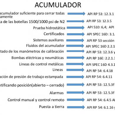
Normas Api
January 2021 2
Api 17f
February 2021 1
Api-542
February 2021 1
Api Hf3
February 2021 1
Api 6am
January 2021 2More Documents from "Nafaka1703"

Api - 682.pdf
February 2021 0
Applications Of Solar Energy
January 2021 0
Drake - "views" Digital Booklet
February 2021 0
Laporan Pendahuluan Epilepsi
January 2021 1
Khoisan Healing Thesis
January 2021 1