Chapter 3 - Well Completion Practices.pdf
This document was uploaded by user and they confirmed that they have the permission to share it. If you are author or own the copyright of this book, please report to us by using this DMCA report form. Report DMCA
Overview
Download & View Chapter 3 - Well Completion Practices.pdf as PDF for free.
More details
- Words: 7,929
- Pages: 138
Loading documents preview...
SKPP 3423 - Well Completion Chapter 3 – Well Completion Practices
Assoc. Prof. Dr. Osman Farag Mohamed Department of Petroleum Engineering Faculty of Chemical & Energy Engineering Universiti Teknologi Malaysia
3.1 Factors affecting well completion 3.2 Types of well completion 3.3 Production tubing size selection
3.4 Completion interval 3.5 Well head installation
Students should be able to: Describe types of completion. Choose a suitable well completion. Choose a suitable tubing size for a given reservoir system. Describe the factors that affect selection of completion interval. Discuss the components of a wellhead assembly.
Recommend wellhead rating to maintain well integrity.
3.1 Factors affecting well completion
The major factors which influence the well completions mainly related to Reservoir Consideration.
Reservoir consideration Reservoir considerations involve:
the location of various fluids in the formations penetrated by the wellbore the flow of these fluids through the reservoir rock the characteristics of the rock itself.
1. Reservoir consideration … (cont.) Producing Rate - to provide maximum economic recovery is often the starting point for well completion design. Among other factors producing rate should determine the size of the producing conduit.
Multiple Reservoirs - penetrated by a well pose the problem of multiple completions in one drilled hole. Possibilities include multiple completions inside casing separated by packers, or several strings of smaller casing cemented in one borehole to provide in effect separate wells.
1. Reservoir consideration … (cont.) Reservoir Drive Mechanism - this may determine whether or not the completion interval will have to be adjusted as gas-oil or water-oil contacts move. A water drive situation may indicate water production problems. Dissolved gas drive may indicate artificial lift. Dissolved gas and gas drive reservoirs usually mean declining productivity index and the increasing gas-oil ratio. Secondary Recovery - needs may require a completion method conducive to selective injection or production. Water flooding may increase volumes of fluid to be handled. High temperature recovery process may require special casing cementing materials.
1. Reservoir consideration … (cont.) Stimulation - may require special perforating patterns to permit zone isolation, perhaps adaptability to high injection rates, and a well hook-up such that after the treatment the zone can be returned to production without contact with killing fluids.
Sand Control - problems alone may dictate the type of completion method and maximum production rates. On the other hand, reservoir fluid control problems may dictate that a less than desirable type of sand control be used. Sand problem zones always dictate a payoff from careful well completion practices.
1. Reservoir consideration … (cont.) Workover - frequency, probably high where several reservoirs must be drained through one wellbore, often dictate a completion conducive to wireline or through-tubing type recompletion systems. Artificial Lift - may mean single completions even where multiple zone exist, as well as larger than normal tubulars.
3.2 Types of well completion
Type of Well Completions Well Classifications Wellbore and reservoir interaction
Flowing path
Flowing method
Inclination
Open Hole
Tubingless
Natural flow
Vertical
Cased Hole
Single
Artificial lift
Deviated
Liner
Multiple
Horizontal
Multilateral
Type of Well Completions Wellbore and reservoir interaction
1. Open Hole Completions Production casing to be set above the zone of interests.
Tubing Production casing
Packer
Type of Well Completions Wellbore and reservoir interaction (cont.) 2. Cased Hole Completion Production casing is cemented through the producing zone and the pay section is selectively perforated.
Production casing
Perfora tion
Type of Well Completions Wellbore and reservoir interaction (cont.) 3. Liner Completions. A liner is install across the pay zone. Can be divided into three: Screen Liner, Slotted Liner, and Perforated Liner.
Tubing Production casing
o 3.a. Screen Liner: Casing is set above the producing zone, and an uncemented screen and liner assembly is installed across the pay zone.
Packer
Screen and liner assembly
Type of Well Completions Wellbore and reservoir interaction (cont.)
3. Liner Completions (cont.)
o 3.b. Perforated Liner Completion: Casing is set above the producing zone, and a liner assembly is installed across the pay zone and cemented in place. The liner is then perforated selectively for production.
Production casing
Liner Perforation
Type of Well Completions Flowing path
1. Tubingless Completions. The tubingless completion method is used in wells where the pay rock pressure is low and high flow rates are required. In this case production must take place directly through the final lining of the well, with no support from production strings or isolation systems.
Production Casing
Perforation
Type of Well Completions Flowing path (cont.)
2. Single String Completions This system has only one tubing string run in hole. Can be divided into four: Packerless, Pakered, Commingle, and Selective.
Type of Well Completions Flowing path (cont.)
2. Single String Completions
o 2.a. Packerless Completion: Packerless completion is a more financially advantageous system. Here, only the production tubing is placed in the well, and it is possible to produce both through it and through the annulus (Fig.). The production tubing can be used for injecting inhibitors or killing fluid. This method is somewhat limited in terms of flow conditions and the protection of the tubing & casing materials. Moreover, it is difficult to detect leaks in the tubing or the casing.
Packerless Single String
Type of Well Completions Flowing path (cont.) 2. Single String Completions (cont.) o 2.b. Packer Single String: The single string completion using hydraulic isolation and just one string. It consists in the use of a single tubing string that is lowered into the well together with an isolation device for the formation section to be produced, called the packer
Packer Single String
Type of Well Completions Flowing path (cont.) 2. Single String Completions (cont.) o 2.c. Commingle Single String: The single string completion using hydraulic isolation and just one string is convenient when the production layers appears to be homogeneous and a selective-zone production is not necessary.
Commingle Single String
Type of Well Completions Flowing path (cont.)
2. Single String Completions (cont.)
o 2.d. Selective Single String: Where there are several production layers for one fluid, a single selective completion is used. This system has only one tubing string and several packers that isolate the various production levels. By using wire-line operations it is possible to open and close the valves so as to allow production on single layers. Selective single string
Type of Well Completions Flowing path (cont.) 3. Multiple String Completions The multiple tubing string completion uses, at the most, two (Dual-String) or three tubings, isolated by packers and producing on different levels at the same time (Fig.). This solution is useful when the reservoir presents different layers of mineralization, for example gas and oil, or different types of oil, because it allows us to produce selectively according to necessity, while keeping production active on various levels at the same time. For the single tubing strings, it is always possible to adopt a solution similar to the single selective completion, thus obtaining a multiple selective completion. This system’s drawback is the limited diameter of the tubing which in turn reduces the flow capacity of each tubing string.
Selective single string
Type of Well Completions Flowing method
1. Natural Flow Completion A well in which the formation pressure is sufficient to produce oil at a commercial rate without requiring a pump. Most reservoirs are initially at pressures high enough to allow a well to flow naturally.
Nodal analysis
Type of Well Completions Flowing method (cont.) 2. Artificial Lift Completion Definition - Any system that adds energy to the fluid column in a wellbore with the objective of initiating and/or improving production from the well. So, the main purpose of artificial lift systems is to provide the fluid with the necessary energy to reach the surface and continue flowing to the primary treatment plants.
Artificial lift systems
The main types of lifts are: a) Sucker rod pumps; b) Hydraulic lifts; c) Electrical Submersible Pumps (ESP); d) Gas lifts; e) Progressive Cavity Pumps (PCP).
Type of Well Completions Flowing method (cont.) 2. Artificial Lift Completion (cont.) a)
Sucker rod pumps (SRP) AL with SRP are made up of a cylinder, a piston, an aspiration valve and a release valve. The piston is connected to the surface by a string of pipes, and is activated by an eccentric system or a crank and slotted link that transforms the engine’s rotary movement into an up and down motion. During the descending phase, the valve in the piston opens and the one in the cylinder shuts. This ensures the passage of the oil from the cylinder towards the delivery pipe above the piston. During the ascending phase, the valve in the piston shuts and the one in the cylinder opens. In this manner, the piston pushes the liquid in the delivery pipe up to the surface enabling more oil to be sucked in to fill the cylinder.
Type of Well Completions Flowing method (cont.) 2. Artificial Lift Completion (cont.) b)
Hydraulic lifts Hydraulic pump systems use a power fluid—usually light oil or water—that is injected from the surface to operate a downhole pump. Multiple wells can be produced using a single surface power fluid installation. With a reciprocating hydraulic pump, the injected power fluid operates a downhole fluid engine, which drives a piston to pump formation fluid and spent power fluid to the surface. A jet pump is a type of hydraulic pump with no moving parts. Power fluid is injected into the pump body and into a smalldiameter nozzle, where it becomes a low-pressure, high-velocity jet. Formation fluid mixes with the power fluid, and then passes into an expanding-diameter diffuser. This reduces the velocity of the fluid mixture, while causing its pressure to increase to a level that is sufficient to lift it to the surface.
Type of Well Completions Flowing method (cont.) 2. Artificial Lift Completion (cont.) c)
Electrical Submersible Pumps (ESP) An electric submersible pumping (ESP) assembly consists of a downhole centrifugal pump driven by a submersible electric motor, which is connected to a power source at the surface
Type of Well Completions Flowing method (cont.) 2. Artificial Lift Completion (cont.) d) Gas lifts A gas lift completion allows hydrocarbons to reach the surface by means of the reduction of the hydrostatic load downhole. Gas lift involves injecting high-pressure gas from the surface into the producing fluid column through one or more subsurface valves set at predetermined depths. There are two main types of gas lift: 1. Continuous gas lift, where gas is injected in a constant, uninterrupted stream. 2. Intermittent gas lift, which is designed for lower-productivity wells. In this type of gas lift installation, a volume of formation fluid accumulates inside the production tubing. A high-pressure “slug” of gas is then injected below the liquid.
Type of Well Completions Flowing method (cont.) 2. Artificial Lift Completion (cont.) e) Progressive Cavity Pumps (PCP) As the rotor turns, cavities between the rotor and stator move upward. Progressive cavity pumps are commonly used for dewatering coalbed methane gas wells, for production and injection applications in waterflood projects and for producing heavy or high-solids oil. They are versatile, generally very efficient, and excellent for handling fluids with high solids content. However, because of the torsional stresses placed on rod strings and temperature limitations on the stator elastomers, they are not used in deeper wells.
Type of Well Completions Inclination
1. Vertical Completion A vertical well is a borehole that is aimed directly at a target beneath it. A vertical well does not have a truly vertical borehole, but it is more or less aimed straight down at a reservoir of oil or gas rather than being turned horizontally at a designated point.
Vertical
Deviated
Type of Well Completions Inclination (cont.) 2. Deviated Completion Deviated completion refers to complete a wellbore to reach a target, or a number of targets, located at some horizontal distance from the top of the hole.
Type of Well Completions Inclination (cont.) 3. Horizontal Completion A horizontal well is a well which has sections that have been drilled at more than 80 degrees from the vertical in order to penetrate a greater length of the reservoir. A well which has sections more than 80 degrees from the vertical is called a horizontal well.
Type of Well Completions Inclination (cont.)
4. Multilateral Completion A multilateral completion is a completion that has two or more drainage holes (or secondary laterals or branches or arms or legs) drilled from a primary well bore (or trunk or main bore or mother bore or backbore). Both trunk or branches can be horizontal, vertical or deviated.
Type of Well Completions Well Classifications Wellbore and reservoir interaction
Flowing path
Flowing method
Inclination
Open Hole
Tubingless
Natural flow
Vertical
Cased Hole
Single
Artificial lift
Deviated
Liner
Multiple
Horizontal
Multilateral
3.3 Production tubing size selection
Introduction The pipe centred in the annulus of an oil and/or gas well through which the hydrocarbons flow from the formation to the surface is called tubing. It is important to size tubing properly. If too small, production will be restricted, limiting the profitability of the well, also may erosion occurs. However, tubing that is too large can reduce fluid velocity and allow for build up of produced water that can kill the well. Large tubing will also affect the economics of the project, adding to the cost of the overall well design.
Introduction (cont.) Tubulars are selected for the specific conditions anticipated in a given well. The anticipated production flow rates and economics of the well determine tubing size, which then determines the necessary size of each previous hole and tubular. Once the tubular size and setting depths are determined, the wall thickness and grade of material are then chosen by the well designer to ensure the strength is adequate for the expected loads. Material grade is also selected to ensure it is appropriate for the fluids the tubular will encounter; corrosion resistant alloys (CRA) may be required in some environments such as CO2 or H2S. Finally, tubular connections are selected based on dimensional needs, load capacity, and gas-vs-liquid seal-ability.
Elements of Tubing Size Selection
Usually requires a nodal analysis program and some very good information about the well’s productivity over time.
An error in the flow data can cause a quick error in the tubing sizing.
Nodal Analysis Instructional Objectives
Explain the concept of Nodal Analysis. List 4 segments in the reservoir/well system where pressure loss occurs.
Define the following terms: - Inflow Performance Curve, - Outflow Performance Curve, - System Graph, - Solution Node.
Nodal Analysis (cont.)
The systems analysis approach, often called NODALTM Analysis, has been applied for many years to analyze the performance of systems composed of interacting components. Electrical circuits, complex pipeline network and centrifugal pumping systems are all analyzed using this method.
The procedure consists of selecting a division point or node in the well and dividing the system at this point. The location of the most commonly used nodes are shown in the following slides.
Nodal Analysis (cont.)
All the components upstream of the node comprise the inflow section, while the outflow section consists of all the components downstream of the node.
A relationship between flow rate and pressure drop must be available for each component in the system. The flow rate through the system can be determined once the following requirements are satisfied: • Flow into the node equals flow out of the node • Only one pressure can exists at a node.
Nodal Analysis (cont.)
Nodal Analysis (cont.) Once the node is selected, the node pressure is calculated from both directions starting at the fixed pressures. Inflow to the node: PR – p (upstream components) = Pnode
Outflow from the node: Psep + p (downstream components) = Pnode
Solution Node at Bottom Hole How do we determine the right flow rate? We know the separator pressure and the average reservoir pressure.
We start in the reservoir at the average reservoir pressure, pr, and assume a flow rate. This lets us calculate the pressure just beyond the completion, pwfs. We can then calculate the pressure drop across the completion, and the bottomhole pressure pwf. This pressure is valid only for the assumed flow rate.
Or, we may start at the separator at psep, and calculate the pressure drop in the flowline to find the wellhead pressure, pwh. Then we can calculate the bottomhole pressure pwf. Again, this pressure is valid only for the assumed flow rate.
The two calculated bottomhole pressures will probably not be the same. If not, then the assumed rate is wrong.
“Nodal” analysis refers to the fact that we have to choose a point or “node” in the system at which we evaluate the pressure – in this case, the bottom of the wellbore. This point is referred to as the solution point or solution node.
Solution Node at Bottom Hole (cont.) Lets assume that the well is completed open hole, and that the well is neither damaged nor stimulated. In this case, the pressure drop across the completion is zero. For the moment, we ignore the wellbore and the flowline. If the flow rate is 0, the bottomhole pressure pwf will be the same as the average reservoir pressure, pr. As we increase the flow rate, the pressure drop in the reservoir segment increases - causing the bottomhole pressure pwf to decrease. When we graph the flowing bottomhole pressure as a function of flow rate, the result is a curve intersecting the y-axis at the initial reservoir pressure, and intersecting the x-axis at the maximum rate the well would produce if opened to the atmosphere at the perforations. This curve is usually referred to as the “inflow curve” or the “reservoir curve”. Until we take into account the pressure drop within the wellbore, this curve tells us very little about the rate at which the well will produce for a given wellhead pressure.
Solution Node at Bottom Hole (cont.) Now let’s assume that the separator is so close to the wellhead that we may ignore the pressure drop through the flowline. At some low flow rate, perhaps 200 STB/D, the flowing bottomhole pressure may be 1500 psi. In order to increase the flow rate without changing the surface pressure, we have to raise the flowing bottomhole pressure. This curve is usually referred to as the “outflow curve” or the “tubing performance curve”. Until we take into account the reservoir behavior, this curve also tells us almost nothing about the rate at which the well will produce.
Solution Node at Bottom Hole (cont.) The inflow curve describes the relationship between the bottomhole pressure and the flow rate in the reservoir.
The outflow curve describes the relationship between the bottomhole pressure and flow rate in the wellbore. When we graph these two curves on the same graph, we refer to this as the “system graph”. The intersection of the inflow curve and the outflow curve gives the one unique flow rate at which the well will produce for a specified set of reservoir and wellbore properties. The point of intersection will also give the unique bottomhole pressure at which this rate will occur. If we had chosen a different point as our solution node, the shapes of the curves would have been different. The y-coordinate of the intersection of the inflow and outflow curves would have given the pressure at the new solution node. The flow rate at which the curves intersect, however, will be the same no matter where the solution node is taken. Calculated intersection points may differ slightly because of numerical errors.
Solution Node at Wellhead What if we take the solution node at the wellhead? Again, we know the separator pressure and the average reservoir pressure. As with the bottomhole node, we start in the reservoir at the average reservoir pressure, pr, and assume a flow rate. This lets us calculate the pressure just beyond the completion, pwfs. We can then calculate the pressure drop across the completion, and the bottomhole pressure pwf. Finally, we calculate the pressure drop up the wellbore to find the wellhead pressure pwh. This pressure is valid only for the assumed flow rate.
Solution Node at Wellhead (cont.)
Tubing Sizing Analysis For Tubing Sizing Analysis The node is selected at the Wellbore The flow into the node is called INFLOW, while flow out of the node is called OUTFLOW At the selected node, whenever the system can flow, two conditions are always satisfied: o Flowrate into node = Flowrate out of node
o ONLY one pressure can exists at the node = Pnode = Pwf
Tubing Sizing Analysis
The tubing size selection should be made before a well is drilled because the tubing size dictates the casing size which dictates the hole size.
Sensitivity analysis can help to identify flow restrictions in the well.
This slide shows how the size of the production tubing affects the well production.
There is an optimum size for any well system. Tubing too small will restrict the production rate because high friction losses. On the other hand a tubing too large may cause a well load up with liquid and die.
Tubing Sizing Analysis Nodal Analysis Applications Selecting tubing size Selecting flow-line size Gravel pack design Artificial lift design Identifying flow restrictions Surface choke sizing Effects of perforating density Subsurface valve sizing Well stimulation evaluation
Inflow Performance Relationship, IPR (cont.) Darcy's law works great for single phase fluid flowing into a reservoir but when gas comes "out of solution" in the reservoir the free gas in the reservoir will compete with the liquid phase for the space available in the reservoir
Graphically it would look like this graph:
Pr < Pb Pwf Pressure - psi
The liquid flow we get as the friction loss in the reservoir is increased will be less than we would predict using Darcy's law!
0
Darcy's law predicted Qmax
Actual Qmax
0
Q - Flow Rate (BPD)
Inflow Performance Relationship, IPR (cont.)
Inflow Performance Relationship, IPR (cont.) When the average reservoir pressure is above the bubble point and the flowing bottom hole pressure is below the bubble point, a combined approach using straight line and Vogel will describe the process.
Inflow Performance Relationship, IPR (cont.)
Vogel IPR Curve: 𝑞 𝑞𝑚𝑎𝑥
𝑃𝑤𝑓 𝑃𝑤𝑓 = 1 − 0.2 − 0.8 𝑃 𝑃
2
Straight line IPR: 𝑞 𝑞𝑚𝑎𝑥 where
𝑃𝑤𝑓 =1− 𝑃
Pwf = bottom hole flowing pressure P = maximum shut-in bottom hole pressure
Example – Inflow Performance Relationship, IPR
Example – Inflow Performance Relationship, IPR
Example – Inflow Performance Relationship, IPR
Example – Inflow Performance Relationship, IPR
Example – Inflow Performance Relationship, IPR
Tubing Performance Curve (TPC) This section discusses the flow through the tubing in the well. The objective is to calculate the pressure loss in the tubing as a function of flow rates of different flowing rates.
Tubing Performance Curve (TPC) (cont.) This equation applies to any fluid in a steady state flow condition. An important thing to note in this equation is that the total pressure gradient is the sum of three principal components. Elevation accounts for approximately 80% of total pressure drop, range from 70 to 98% Friction accounts for most of remaining pressure drop
Acceleration accounts for only a very small amount of pressure drop where
d - pipe diameter f - friction factor g - acceleration of gravity gc - conversion factor P - pressure v - velocity Z - distance along flow path - density
Subscripts m - mixture properties
Tubing Performance Curve (TPC) (cont.) Holdup is the fraction of the total volume in the pipe occupied by liquid.
Once the holdup is known, the mixture density is readily determined from the gas and liquid densities.
Tubing Performance Curve (TPC) (cont.)
The pressure – depth profile is called a pressure traverse and is shown in the figure above. The total pressure at the bottom of the tubing is function of flowrate and the following elements: 1. Wellhead pressure – back pressure exerted at the surface from choke and wellhead assembly 2. Hydrostatic pressure – due to gravity and the elevation change between wellhead and the tubing intake. 3. Friction losses – includes irreversible pressure losses due to viscous drag and slippage.
Tubing Performance Curve (TPC) (cont.) The Vertical Flow Pressure Gradient Curve is widely used for establishing TPC. These curves are established based on vertical flow correlations applicable to particular flow conditions. The correlations are: 1) For vertical multiphase flow (oil wells) a) Hagedorn and Brown b) Duns and Ros c) Ros and Gray
d) Orkiszewski e) Beggs and Brill f) Aziz
2) For vertical flow (dry gas wells) a) Cullender, Smith, and Poettman 3) For vertical flow (wet gas wells) a) Ros and Gray b) Beggs and Brill No one correlation satisfies all well conditions.
Construction of TPC Using Gradient Curves Exercise – Application Given,
Pwh = 100 psig WHT = 70 °F Tres = 140 °F GLR = 400 scfbbl g = 0.65 Depth = 5,000 ft (mid-perf.) Tubing ID = 2 in. API Gravity = 35O API Calculate and plot the tubing intake curve.
Construction of TPC Using Gradient Curves (cont.) Solution A plot of the bottomhole flowing pressure vs flow rate is obtained based on pressure gradients in the piping. Use the following pressure gradient curves.
1. Using Fig. 1, start at the top of the gradient curve at a pressure of 100 psig. Proceed vertically downward to a gas liquid ratio of 400 scf/bbl. Proceed horizontally from this point and read an equivalent depth of 1,600 ft. 2. Add the equivalent depth to the depth of the well at mid-perforation. 3. Calculate a depth of 6,600 ft. on the vertical axis, and proceed horizontally to the 400 scf/bbl GLR curve. From this point, proceed vertically upward and read a tubing intake pressure 730 psig for 200 BPD.
Construction of TPC Using Gradient Curves (cont.) 4. Repeat the procedure for flow rates of 400, 600, and 800 BPD using Figs. 2 through 4, respectively. 5. Plot the Pwf vs q values tabulated below as shown in Fig. 5 to complete the desired tubing intake curve.
Assumed q (BPD) 200 400 600 800
Pwf (psig) 730 800 880 1000
Construction of TPC Using Gradient Curves (cont.)
Fig . 1
Construction of TPC Using Gradient Curves (cont.)
Fig . 2
Construction of TPC Using Gradient Curves (cont.)
Fig . 3
Construction of TPC Using Gradient Curves (cont.)
Fig . 4
Construction of TPC Using Gradient Curves (cont.)
Fig . 5 This figure shows a tubing intake or outflow performance curve for a wellhead pressure of100 PSIG.
System Analysis For the system analysis, IPR and TPC are plotted together. The intersection of IPR and TPC will give the flowrate of the system.
At condition at which no intersection occurs between IPR and TPC, the well cannot flow at the specified conditions. Adjustments of the controllable parameters have to be made to lower down the TPC.
System Analysis (cont.)
System Analysis (cont.) Tubing Performance Curves with Inflow Performance Relationship
System Analysis (cont.)
System Analysis (cont.) IPR Change After Some Reservoir Depletion
System Analysis (cont.) Production Rate and Tubing Sizing
System Analysis (cont.) What Happens When TPC and IPR Curves no longer meet?
System Analysis (cont.) What Happens When TPC and IPR Curves no longer meet?
Tubing Sizing Requirement Related to Well Performance Analysis Deliver the desired production/injection rate Avoid inefficient and unnecessary artificial lift Avoid liquid load up problems especially in two-phase flow of gas wells Produce/Inject at velocity below the erosional velocity
Exercise – IPR & Tubing Size Selection
Exercise – IPR & Tubing Size Selection (cont.)
Exercise – IPR & Tubing Size Selection (cont.)
Exercise – IPR & Tubing Size Selection (cont.)
Exercise – IPR & Tubing Size Selection (cont.)
Exercise – IPR & Tubing Size Selection (cont.)
Exercise – IPR & Tubing Size Selection (cont.)
3.4 Completion interval
1. Specific perforation objectives 2. Cement bond 3. Open hole log
4. Contacts 5. Perforation analysis and conditions
1. Specific perforation objectives A perforation program is normally part of the well completion, well test, re-perforation or workover program. Define the specific objectives first as it will determine the other requirements. One or more of the following may be the objectives : To complete and produce an oil or gas zone at maximum productivity and recovery. To perform cement remedial operation. To gravel pack.
1. Specific perforation objectives (Cont’d) To perforate the water leg of an oil zone for water injection at maximum injectivity. To perforate the gas column of an oil zone for gas injection at maximum injectivity. To perforate at optimum cost and productivity/injectivity. To re-perforate a zone with low production rates
2. Cement Bond Evaluation of the cement quality behind casing near the zone of interest to ensure that perforation objectives are met. Cement quality is good enough to ensure water or gas from nearby zones or columns (within the same sand) are isolated behind casing.
Perforation interval may need to be reduce to ensure isolation behind casing if remedial cementing will not be carried out.
3. Open hole Logs Evaluate Open-hole logs to look for contacts nearby sands and sand quality of perforated intervals. General rules to select perforation interval for high productivity : o Good sand based on porosity cutoff with the desired fluids type (oil or gas) must be perforated : Perforate more than the interval with good porosity. In laminated sands, perforate across the whole interval to ensure good permeability unless shale layers are obvious.
4. Fluid Contacts and Nearby Sands Fluid contacts (GOC, OWC, GWC), reservoir drive and nearby sands to be considered. Some guidelines are : If GOC and OWC present at or nearby the well or reservoirs with both water and gas cap drive of equal strength: Perforate 1/3 to 1/4 of oil column height for the OWC and 2/3 to 3/4 of oil column from GOC. Strong water drive reservoirs : Perforate as high or far from the reservoir OWC as possible. Strong gas cap drive with weak water drive reservoirs : Perforate as low or far from the reservoir GOC as possible
4. Fluid Contacts and Nearby Sands (Cont’d) Gas reservoir with strong water drive : Perforate as high or far from the reservoir OWC as possible Mobility of oil, gas and water which are functions of viscosity, fluid saturation, porosity and permeability can be calculated from simulation, laboratory and correlation can be used to determine distance of perforation from OWC/GOC/GWC.
Perforate away from nearby sands which may interfere with production and recovery if poor cement are suspected.
4. Fluid Contacts and Nearby Sands (Cont’d)
5. Perforation Analysis and Conditions An analysis to determine the following conditions to achieve the objectives of optimum productivity or injectivity must be carried out :
• Charge Type : based on penetration required • Shot Density : determine gun type • Shot Phasing : determine gun type • Overbalance / Underbalance required • Gun stand - off : influence on penetration These conditions will be examined to determine the optimum perforation technique i.e.. Wireline, TCP, overbalance or Underbalance. A program called SPAN, can assist in this analysis.. Estimate the total perforation cost including rig time and determine if the increase in productivity justifies the additional cost. In general any increase in productivity can justify the increase cost of ensuring maximum productivity.
3.5 Well head installation
Overview All wells are lined with steel pipe, known as casing, to allow unobstructed access to the target reservoir. Up to four casing strings may be installed and each string is cemented in place to mechanically support the pipe and hydraulically isolate the target reservoir from groundwater sources and other formations. Most wells also include one or more strings of pipe or tubing to recover or “produce” the reservoir fluids, to inject fluid into the reservoir, or to allow other well operations.
All wells are capped by an assembly of steel pipe and fittings known as the wellhead. The wellhead’s function is: Seal & isolates Casings and Tubing's. Allowing access and controlling flow from (or to) tubing and casing annulus.
Simplified Diagram of Casing & Tubing
Basic Components of a Wellhead A wellhead is made up of a series of components that are connected and sealed in various ways. In this section, the following key components of a wellhead (from bottom to top) are covered. Bear in mind not every wellhead requires all of these components since the need for each depends on the type of well, the well completion, and expected operation. Casing Head Casing Spool Casing Hangers Tubing Head Tubing Hanger Tubing Head Adaptor Christmas Tree
Basic Components of a Wellhead Casing Head The casing head, also referred to as a casing bowl, is the lowest part of the wellhead assembly. The bottom of the casing head is configured to attach to the casing below (typically, the surface casing). The upper inside of the casing head provides a bowl in which the next casing string can be set and sealed (if required). The top of the casing head then connects to the next wellhead component. Access to the annulus between the surface casing and the next casing string is available through side outlets.
Basic Components of a Wellhead Casing Head (Cont’d) The function of the casing head is to: Isolate the inside of the surface casing from the outside environment. Provide a platform for and a means to test the rig BOP stack during drilling and well servicing operations. Support or transfer the weight of drilling and workover equipment during drilling and well servicing operations. Allow for suspending and packing off the next casing string (i.e., intermediate or production casing). This is accomplished by setting a casing hanger and seal against the recessed profile machined into the upper inside surface (bowl). The hanger often is held in place by lockdown screws and the seal thus formed against the casing string is called the primary seal. Provide access to the surface inner casing annulus for monitoring and fluid return purposes. Access to the annulus is available through side outlets drilled through the casing head. After the well is completed, one of the side outlets may be converted to a surface casing vent. This can then be used to monitor any flows or pressure build up of gas, water or hydrocarbon liquids within the surface casing annulus. These can indicate a failure in the integrity of the inner casing cement, production casing, or annular seals that may present an environmental hazard.
Basic Components of a Wellhead Casing Spool If a well includes one or more intermediate casing strings between the surface and production casing, the next component required after the casing head is the casing spool. The bottom of the casing spool mounts on top of a casing head or previous spool, and the top connects to the next spool or tubing head assembly. The spool is designed so the bottom bowl or counterbore will allow a secondary seal to be set on the previous casing string, while the top bowl will hold a casing hanger to suspend and allow a primary seal around the next string of casing. Multiple casing spools may be used, one on top of the other, to hang intermediate casing strings and the final production casing string.
Basic Components of a Wellhead Casing Spool (Cont’d) The function of the casing spool assembly is to: Allow for a secondary seal on the previous casing string in the counterbore. With a secondary seal in place, flange or hub seals and casing hanger seals are isolated from internal casing pressure. Provide a port for pressure testing primary and secondary casing seals and flange connections.
Provide a platform to support, seal and pressure test the BOP during drilling and well servicing operations. Provide a load shoulder and controlled bore in the top bowl to support the next casing hanger and enable a primary seal for the next intermediate or production casing. Provide annular access for fluid returns or fluid injections and pressure monitoring, through side outlets drilled in the spool assembly.
Basic Components of a Wellhead Casing Hangers Both casing heads and casing spool assemblies may require the use of casing hangers. Casing hangers attach to the end of a given casing string and suspend and seal the casing string in the top bowl of a casing head or spool. Casing hangers come in two main varieties: • Slip type hangers that are installed around the casing after it is run, either before or after the casing is cemented into place. o Slip type casing hangers are used as a contingency when pipe is stuck, allowing the casing to be cut off and set where it sits. • Mandrel type hangers that are threaded onto the casing. o Mandrel type casing hangers provide superior well control when landing the hanger and improve the annular seal.
Basic Components of a Wellhead Casing Hangers (Cont’d) When a casing hanger is used, shallow intermediate strings are usually suspended from the hanger and then cemented to surface. Longer intermediate and production strings that are not cemented to surface are usually cemented while the casing is suspended in tension from the rig traveling block. After the cement has set for a few hours, the traveling block pulls a calculated tension on the casing above the cement and it is at this point the hanger is set in the bowl. Casing hangers are often called slips or seals as they are designed with built-in seals. Slips may occasionally be run without seals in shallow wells where a primary seal is then installed whenever the BOP or Christmas tree is removed. A hanger may also be held in-place in the upper bowl of a casing head or spool assembly by the use of lock-down (also called hold-down) screws.
Basic Components of a Wellhead Casing Hangers (Cont’d) The function of the casing hanger is: To suspend the load of the casing string from the casing head or spool. To centre the casing in the head. To provide a primary seal against the inside of the casing head and isolate the casing annulus pressure from upper wellhead components.
Basic Components of a Wellhead Tubing Head The tubing head assembly provides a means to suspend and seal the production tubing in the wellhead. The tubing head is the top spool in the wellhead assembly and is installed after the last casing string is set. The bottom of the tubing spool includes a counterbore that can be used to set a seal against the production casing. The top of the tubing head provides a landing shoulder and a seal bore for landing and enabling a seal to the tubing hanger. Above the tubing head is the tubing head adaptor which provides a transition to the Christmas tree.
Basic Components of a Wellhead Tubing Head (Cont’d) Tubing heads come in three basic connection configurations. Well type and conditions are used to determine which type of tubing head is most appropriate for the operation. 1. Top connection threaded; bottom connection threaded or welded. 2. Top connection flanged; bottom connection threaded or welded. 3. Top and bottom connection flanged or clamp hub
Tubing Head Threaded by Threaded or Welded
Tubing Head Flanged by Threaded or Welded
Basic Components of a Wellhead Tubing Head (Cont’d) The function of the tubing head assembly is to: Enable the suspension of the tubing. Allow for sealing the annulus between the tubing and the production casing. Allow access to the annulus between the tubing and production casing, through side outlets.
Provide a means to support and test the service rig BOP during well completions. Provide a bit guide for running the tubing without causing damage to the production casing.
Basic Components of a Wellhead Tubing Hanger A tubing hanger is also commonly known as a dog nut. A tubing hanger typically is threaded onto the top of a tubing string and is designed to sit and seal in the tubing head. Usually the tubing hanger is run through the BOP and landed in the top bowl of the tubing head. The top of the tubing hanger provides a profile necessary for the lock screws that will secure the hanger in the tubing head. In a simple, single string completion the hanger carries the weight of the tubing and the tubing is “hung in neutral”. In other completions where the tubing–casing annulus must be isolated from the fluid handled (e.g., produced water injection or disposal wells), different intervals must be isolated from each other, or gas will be injected to enhance fluid production (i.e., in a gas lift well), hanger design must also consider the use of a downhole packer where the tubing may be set in compression, tension or neutral, and upward (compression) forces may be placed on the tubing string during production or injection operations.
Tubing hanger design / hold downs also should consider the dynamic loads that can be applied in artificial lift wells by the reciprocating motion of a rod string and torque induced at the start-up and shut-down of ESPs and PCPs.
Basic Components of a Wellhead Tubing Hanger (Cont’d) Standard, single or dual tubing hangers with seal rings or elastomers provide a seal between the tubing hanger and tubing head below the lock down screws.
Basic Components of a Wellhead Tubing Hanger (Cont’d) Extended neck tubing hangers allow for a primary and secondary seal on the tubing hanger. In this configuration, a secondary seal packs off inside the tubing head adaptor. As a result, the lock down screws are isolated from the well bore fluids and the primary and secondary seals can be pressure tested. Extended neck tubing hangers are required for sour wells and possibly corrosive wells. Because tubing head components and seals are uniquely exposed to production and injection fluids, special consideration needs to be given to the metallurgy and elastomer seal selection.
Basic Components of a Wellhead Tubing Hanger (Cont’d) Tubing hangers may come with a back pressure thread profile that enables the operator to lubricate an isolation plug into the tubing hanger. With an isolation plug in place, pressure testing can now be carried out above the tubing head. It also provides well control for installing and removing the BOP or Christmas Tree, and for temporary well suspensions.
Basic Components of a Wellhead Tubing Head Adaptor The tubing head adaptor provides a transition from the tubing head to the Christmas tree. With a basic tubing head configuration where the tubing hanger is seated in the top of the tubing head, the bottom of the tubing head adaptor will seal against the tubing head and contain reservoir or injection fluids moving through the top of the tubing. With an extended neck tubing hanger, the adaptor will provide a secondary seal against the hanger, isolating the seal between tubing head and adaptor and any lock screws holding the tubing hanger in place. As such, this configuration provides a means to test the primary and secondary seals on the tubing hanger.
Basic Components of a Wellhead Christmas Tree A Christmas tree is an assembly of gate valves, chokes and fittings included with the wellhead during well completion. The Christmas tree provides a means to control the flow of fluids produced from or fluids injected into the well, at surface. While Christmas trees come in a variety of configurations based on a number of well design and operating considerations, typically the bottom connection of the tree matches the top connection of the tubing head adaptor and these are generally installed as a unit, immediately after production tubing is suspended.
Basic Components of a Wellhead Christmas Tree (Cont’d) A typical Christmas tree components on a flowing, gas lift, or injector well can be seen in Figure. These components include: A minimum of one master valve that will control all flows to and from each tubing string. Under certain service conditions and well pressures, additional master valves. o The upper valve is typically used in routine operations while the lower valve provides backup and the ability to service the upper valve as the need arises. A tee or cross leading to control valves such as production gate valves, surface safety valves, flow control valves or chokes Potentially a swab valve above the tee that permits vertical access to the wellbore.
A tree cap that might be fitted with a pressure gauge. The tree cap provides quick access to the tubing bore for bottom hole testing, installing down hole equipment, swabbing, paraffin scraping, and other thru-tubing well work.
Basic Components of a Wellhead Christmas Tree (Cont’d) A Christmas tree may be modified based on well operating conditions, fluids produced and recovery methods. In the case of an assisted lift well that requires a rod string to run through the Christmas tree (e.g., reciprocating rod pumping or PCP, see Figure), the configuration is adjusted as follows: The master valve is either removed or incapacitated to prevent accidental closure. The addition of a polished rod BOP that can be closed around the polished rod to seal fluid and pressure in the wellhead if required. The polished rod BOP may be activated either manually or hydraulically. The addition of a stuffing box that provides a seal around the moving polished rod during operations.
The inclusion of an environmental BOP that seals across the tubing bore in the event a polished rod breaks and is pulled or ejected out of the stuffing box. It may be integrated into the stuffing box itself or be installed as a separate component above or below the stuffing box.
Basic Components of a Wellhead Christmas Tree (Cont’d) Christmas Tree on Dual Completion Well
Wellhead and X-Tree Installation The wellhead flange attaches to the first cemented surface casing string designed to hold pressure.
Wellhead and X-Tree Installation (Cont’d) Well flange attachment to the casing may be by welding, forming, threaded connection or set screws.
Wellhead and X-Tree Installation (Cont’d) The second string of casing is run and the hanger is landed in the bowl.
Wellhead and X-Tree Installation (Cont’d) The second string of casing is run and the hanger is landed in the bowl. Hanger set in the casing spool
Lock down screws engaged
Annular access port
Wellhead and X-Tree Installation (Cont’d) The tubing head follows.
Wellhead and X-Tree Installation (Cont’d) The tubing is landed in the spool.
Wellhead and X-Tree Installation (Cont’d) Lock down pins are engaged and the seal activated.
Wellhead and X-Tree Installation (Cont’d) One or two full opening master valves come next.
Wellhead and X-Tree Installation (Cont’d) Followed by the flow T or Cross.
Wellhead and X-Tree Installation (Cont’d) The tree before adding control valves.
Wellhead and X-Tree Installation (Cont’d)
Wellhead and X-Tree Installation (Cont’d)
Wellhead and X-Tree Installation (Cont’d)
Wellhead and X-Tree Installation (Cont’d)
Related Documents

Chapter 3 - Well Completion Practices.pdf
February 2021 0
3-well Completion-136s
February 2021 0
Chapter 6-well Completion Utm
February 2021 1
Part 3 Well Completion Equipment.pdf
March 2021 0
Well Completion And Operations
February 2021 5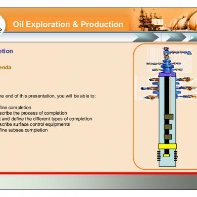
Basics Of Well Completion-ep
January 2021 0More Documents from "Hamdan Hamzah"