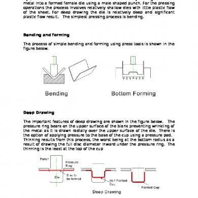
Deep Drawing
This document was uploaded by user and they confirmed that they have the permission to share it. If you are author or own the copyright of this book, please report to us by using this DMCA report form. Report DMCA
Overview
Download & View Deep Drawing as PDF for free.
More details
- Words: 987
- Pages: 2
Loading documents preview...
Tooling Technology
TOOLING BY DESIGN
PETER ULINTZ
Deep-Drawing Guidelines—Cups Part 1 ne of the most complex metalforming operations is the deepdrawing process. In most sheetmetal-forming operations the finished part is stretched or squeezed into a desired shape. This is particularly true for bending, flanging, extruding, embossing and coining. But in deep drawing the objective is to force the sheetmetal to flow into a die cavity to produce the required shape with minimal stretching and thinning of the material. Deep drawing can be defined as a metalforming process in which a part is produced from a flat sheetmetal blank by the action of a punch force onto the blank. The blank is pulled (drawn) into a die cavity, which causes the flange of the blank to compress in the circumferential direction while material flow is controlled by a restraining force pro-
O Peter Ulintz is Advanced Product Engineering Manager for Anchor Manufacturing Group, Inc., Cleveland, OH. Having worked in the metalforming industry since 1978, his background includes tool and die making, tool engineering, engineering management, advanced process planning and product development. Ulintz has been speaking at PMA seminars, symposiums and roundtables since 1996, focusing on tool and die technology, deep-draw stamping, metalforming simulation and
vided by a blankholder. Fig. 1 illustrates the basic components in a typical draw-tool arrangement. These components include: the blankholder and related pressure system, a draw punch, a die cavity and a sheetmetal blank. Each of these components contains important features critical to the success of the drawing operation. The draw punch applies the required force onto the sheetmetal blank in order to cause the material to flow into the die cavity. The critical features of the draw punch include the punch face and punch-nose radius (Rpn). The punchnose radius cannot be too small as it will try to pierce or cut the blank rather than force the material to bend around the radius. The minimum punch-nose radius depends on material type and thickness. Limitations have been established through years of empirical testing
metalforming problem solving. His published technical works include a computer-assisted deep-drawing method and metalforming-simula-
Die face
tion case studies.
Die cavity
Peter Ulintz [email protected]
Rd
www.toolingbydesign.com
Blankholder
Blank thickness (t)
Blankholder Rpn
Punch face Punch
Blankholder pressure system
Fig. 1—Draw-tool nomenclature. 52
METALFORMING / FEBRUARY 2007
www.metalformingmagazine.com
Punch radius
16t
16t Minimum acceptable
14t
14t Draw Radius as a Multiple of Material Thickness
Punch Radius as a Multiple of Material Thickness
Middle of acceptable range
12t 10t Good 8t 6t 4t
Bad
2t 0t
0
0.025
0.050 0.075 0.100 Material Thickness (t) in.
0.125
Fig. 2—Minimum punch-nose radii as a function of material thickness.
and field study. Fig. 2, the result of such testing with low-carbon steels, identifies minimum punch-nose radii related to the material thickness of the blank. This ratio of radius (r) to material thickness (t) is commonly referred to as the r/t ratio. It is equally important to understand that as the punch-nose radius is increased the blank will tend to stretch on the punch face rather than draw-in the blank edge. A large radius, especially one that is highly polished, reduces the amount of friction on the punch-face surface. Reducing friction here allows the material to stretch more easily across the punch, the path of least resistance, instead of drawing-in the blank edge. When a large punch radius is required it often is helpful to leave the punch face rough. This increases the coefficient of friction over the punchface surface and discourages material flow, thus helping to pull in the blank flange in toward the die cavity. Avoiding lubrication between the punch face and the blank surface also will help retard material flow. Remember, the objective is www.metalformingmagazine.com
Maximum acceptable 12t 10t
Wrinkling
8t Op tim um ran ge
6t 4t 2t 0t
Splitting
0
0.025
0.050 0.075 0.100 Material Thickness (t) in.
0.125
to cause the blank edge to flow toward Fig. 3—Optimizing the draw radius. the die cavity, not to stretch the blank over the punch face. galling. On the other hand, an excessive The die radius (Rd) and die-face die radius causes the blank to wrinkle in surface are probably the most influenthe unsupported region between the tial features in a draw tool that uses a punch face and the die face. When the flat blankholder. The flat blankholder blank wrinkles, the engineered clearance distinction is made because some draw between the punch and die cavity is tools, with complex product geomereduced by the wrinkle height and try, often have blankholders that are not material flow is impeded and fractures flat but have curvature that wraps the in the stamping result. blank prior to forming. In these tools It is apparent that there must be the blankholder geometry is extremely some range of die radii to select from critical and highly engineered with fully that will work; not too small and not too developed surfaces to ensure that the big. The die radius, similar to the punch blank wrap does not impede material radius, depends on the r/t ratio. The flow after the die closes. But in cup graph in Fig. 3 helps select die radii drawing, flat blankholders are nearly when deep drawing low-carbon steels. always used. Finally, attention to detail in the dieIf the draw radius is too small the design and tool-build process should part may split as the material deforms. reflect the importance of the draw-die This is due to the high restraining forces radius. The die radius must be absolutecaused by bending and unbending of ly smooth, highly polished in the directhe sheetmetal over a tight radius. tion of material flow, and blend perDrawing over a tight radius also profectly into the die wall. duces a tremendous amount of heat. Next month, we’ll discuss drawThis can lead to microscopic welding of reduction ratios and blankholder forces. MF the sheetmetal to the tools, known as METALFORMING / FEBRUARY 2007
53
Related Documents
Deep Drawing
March 2021 0
Deep Drawing
March 2021 0
Deep Drawing
March 2021 0
4 Deep Drawing
March 2021 0
5 Deep Drawing
March 2021 0
Die Design Deep Drawing Report
February 2021 1More Documents from ""