Kupdf.com Ce Reviewer Design
This document was uploaded by user and they confirmed that they have the permission to share it. If you are author or own the copyright of this book, please report to us by using this DMCA report form. Report DMCA
Overview
Download & View Kupdf.com Ce Reviewer Design as PDF for free.
More details
- Words: 7,421
- Pages: 18
Loading documents preview...
Structural engineering and design construction 2012-2013 zherrinore 1. From the given truss, it is made up of guijo 100mm x 150mm. It is subjected to a vertical load of 20 KN acting at C Allowable stress of wooden section Shear parallel to the grain=1.0MPa Shear longitudinal for joints=1.45MPa Compression parallel to grain=1.1MPa Compression perpendicular to grain=5MPa
1. Compute the minimum length of x a. 120 mm b. 140 c. 150 d. 160 e. 130 2. Compute the minimum length of y a. 12.15 b. 14.55 c. 10.75 d. 16.96 e. 20.85 3. Compute the axial stress of member AC a. 1.78 b. 2.36 c. 1.26 d. 2.85 e. 3.33 2. A simply supported beam 10 m long has an overhang of 2m at the left support. If a highway uniform load of 9.35 kN/m and a concentrated load of 116 kN, passes thru the beam compute the fillowing based on the influence line diagram for maximum shear at midspan. 1. Determine the length of the beam where the uniform load could produce maximum positive shear at the mid span a. 6 b. 5 c. 8 d. 7 e. 9 2. Determine the length of the beam where the uniform load could produce maximum negative shear at midspan a. 4
b. 5 c. 6 d. 7 e. 8 3. If the concentrated load will be placed at the end of the overhang, compute the maximum shear at the midspan 3. A timber joist 40mmx190mm spaced at .3 m on centers, carries a floor load of 2.4 kPa including the floor finish. The joist is supported by the girder at 3m. Two lengths of joists are used. L=3m and L=3.5m. EI is constant throughout the span 1. Compute the maximum flexural stress when L=3 a. 4.15MPa b. 5.85 c. 6.35 d. 7.78 e. 3.37 2. What is the maximum flexural stress when L=3.5m a. 1.15 b. 2.87 c. 4.15 d. 5.86 e. 3.18 3. What is the maximum shear stress when L=3m a. .21 b. .12 c. .56 d. .85 e. .98 4. A 12 mm thick steel tire has a width of 110 mm and has an internal diameter of 800mm. The tire is heated and shrunk to a steel wheel 800.5 mm diameter. Modulus of elasticity E=200GPa 1. Determine the tensile stress in the tire a. 125MPa b. 115 c. 108 d. 110 e. 111 2. Determine thbe compressive pressure between the tire and the wheel a. 2.15MPa b. 4.78 c. 3.75 d. 6.33 e. 5.18 3. Determine the thickness of the tire to resist pressure of 1.5 MPa if it has an allowable stress of 124 MPa a. 3.25MPa
Structural engineering and design construction 2012-2013 zherrinore b. 5.15 c. 2.87 d. 8.08 e. 4.84 5. A water tank 3m in diameter and 6 m high is made from a steel having a thickness of 12mm 1. When the tank is filled with water, determine the circumferential stress a. 8.14MPa b. 6.15 c. 9.87 d. 7.36 e. 5.22 2. Determine the longitudinal stress at the bottom of the tank when it is filled with water a. 2.15MPa b. 1.45MPA c. 3.68 d. 4.78 e. 5.36 3. If the circumferential stress is limited to 5MPa, what is the maximum height of water to which the tank maybe filled. a. 5.85 b. 4.08m c. 6.45 d. 7.48 e. 9.23 6. From the figure shown, a uniform load of 112 kN/m is acting downward and supported by an upward uniform pressure of q=48kN/m
1. Determine the maximum shear a. 45 b. 48kN c. 53 d. 64 e. 60 2. Determine the maximum moment a. 40 kN.m b. 48 c. 42 d. 36 e. 33 3. Determine the distance from the left where the flexural stress is zero a. 2.2 m b. 1.4 c. 4.7 d. 3.1 e. 3.5
7. A hollow steel strut with a wall thickness of h=10mm is pin conenected to two gusset plates having a thickness of 12 mm which are welded to the base plate having a thickness of 12mm and fastened to a concrete base by 4-16mm anchor bolts. Diameter of pin is 16mm. Compressive load P=48Kn, ϴ=30⁰
1. Calculate the bearing stress between the strut and the pin in MPa a. 140 b. 30 c. 160 d. 170 e. 150 2. Calculate the shear stress in the pin in MPa a. 112.3 b. 126.7 c. 119.4 d. 105.7 e. 110.3 3. Calculate the shear stress in the anchor bolt in Mpa a. 85.47 b. 51.69 c. 66.35 d. 72.48 e. 80.23 8. Six steel cables are supporting a circular heavy moulding of diameter 2m from an overhead point. If the moulding weighs 2.5kn/m and the attachment point is 3m above it, determine the following 1. Find the tension in each steel wire a. 276 b. 215 c. 245 d. 176 e. 155 2. What is the diameter of the wire that will not exceed the allowable stress of 124 Mpa a. 6 b. 5 c. 4mm d. 3
Structural engineering and design construction 2012-2013 zherrinore e. 7 3. If the wire is 10mm, find the vertical displacement of the molder a. .254mm b. .887 c. .527 d. .369 e. .415mm 9. A W420x85 steel beam is fully restrained with a uniformly distributed superimposed load of 25kn/m. The beam has a span of 10m. Properties of W420 x 85, A=10839 mm2, bf=18mm, tf=18mm, is=310x104, d=420mm, tw=11 1. Compute the bending stress in Mpa a. 168.58 b. 145.83 c. 155.45 d. 178.48 e. 180.23 2. Compute the maximum web shear stress a. 16.77 b. 14.15 c. 15.15 d. 18.36 e. 17.42 3. Compute the maximum horizontal shear stress in Mpa a. 17.41 b. 18.23 c. 16.23 d. 15.28 e. 19.41 10. To retain the backfill, treated timber piles braced by the horizontal struts are anchored to be dropped at 3m spacing. The piles are considered hinged at the base. Unit weight of the soil=17.3kN/m3, ka=1/3, unit weight of water=9.81, h1=2.1m, h2=3.3m, h3=2.7m. allowable bending stress fs=14.7MPa, allowable shear stress fv=1.48MPa. 1. If the struts are hinged at anchor rod location, determine the design maximum moment of the strut a. 75.15 KN.m b. 63.83 c. 70.36 d. 87.42 e. 83.26 2. If the strut depth is 300 mm, determine the safe width in bending a. 300mm b. 250 c. 270
d. 330 e. 290 3. Determine the safe width in shear a. 323 b. 315 c. 288 d. 236 e. 296 11. A 250 mm pole is 3m high is fixed at the base. It is subjected to a compressive force of 3 Kn acting at its centroid and a .45 KN lateral force applied at the top. What is the maximumshear stress in the pole? a. .012MPa b. .025 c. .039 d. .078 e. .045 12. A hollow circular pole 6 mm thick with 300 mm outside diameter and height of 3m weighs 150n/m. The pole is subjected to the following vertical load P=3KN at an eccentricity e=100mm from the centroid of the section, lateral force H=.45 kn at the top of the pole 1. Determine the maximum compressive stress at the base due to the loads a. 1.29Mpa b. 2.36 c. 3.42 d. 4.15 e. .78 2. Determine the maximum tensile stress at the base due to vertical and lateral loads a. -2.36MPa b. -4.15Mpa c. -5.48Mpa d. -8.23MPa e. -3.58 MPa 3. If the hollow pole is replaced by a solid wood pole of 250 mm, determine the maximum shear stress at the base a. .012 MPa b. .025 c. .039 d. .078 e. .015 13. A large pipe called a penstock in hydraulic work is 1.5 m in diameter. Here it is composed of wooden steved bound together by flat steel bands 50 mm wide by 6mm thick with a maximum tensile stress permitted in the steel bands of 300 MPa 1. Determine the maximum bursting pressure if the tank contains water to a
Structural engineering and design construction 2012-2013 zherrinore depth of 30m, max. Density of water is 1000kg/m3 a. 294.3 kPa b. 326.5 c. 278.4 d. 312.6 e. 302.6 2. determine the tensile force in each steel bands if it has a factor of safety of 2.5 a. 35000N b. 34000N c. 37000 d. 36000 e. 38000 3. determine the spacing of the bands near the bottom of the penstock a. 175mm b. 203mm c. 218 d. 358 e. 163 14. A 12 m long beam is simply supported at the right end and at 3m from the left end. It is to be designed for moving uniformly distributed load. For max. Negative moment, what is the total length of the beam which should be loaded? a. 1m b. 2 c. 4 d. 3 e. 5 15. A rectangular footing, .70 m thick, 2.5m wide along the y-axis and 3, long along the x-axis, supports concentrically a column .4m square subjected to the following loads, Axial load=1200kN, moment about y-axis, My=360 kN.m, height of backfill on top of the footing=1.5m, concrete unir weight=24kN/m3, soil unit weight=17kN/m3 1. Calculate the max. Net soil pressure a. 289 kPa b. 326 c. 311 d. 256 e. 308 2. Calculate min net soil pressure a. 53 kPa b. 60 c. 48 d. 64 e. 32 3. Calculate the gross safe soil bearing capacity a. 205.2
b. 197.4 c. 211.3 kPa d. 228.4 e. 190.4 16. A 10m long beam is simply supported at the left end and at 2m from the right end. It is to be analyzed for moving uniformly distributed load, for max. Shear at the midspan. What is the total length of the beam which should be subjected to the moving load? a. 7m b. 8m c. 5m d. 8m e. 9m 17. A barge shown diagrammatically supports the load W1 and W2 for every one meter strip along the longitudinal section.w1=145kn/m w2=290 kn/m l1=3m, l2=6m, l3=3m
1. Find the total length L so that the upwatrd pressure is uniform and that the barge remains horizontal a. 10m b. 12m c. 18m d. 15m e. 22m 2. If the upward pressure is 72 kn/m, what is the ahear at 3m from the left end a. -236kn b. -285kn c. -345 d. -328 e. -219 3. If the upward pressure is 87 kn/m, at what distance from the left end will the shear in the barge be equal to zero? a. 5m b. 4m c. 6m d. 7m e. 8m 18. The horizontal distance from A at one end of the river to frame C at the other end is 20m. The cable carries a load W=50kN.
Structural engineering and design construction 2012-2013 zherrinore 1. at what distance from A is the load W such that the tension in the segment AD of the cable is equal to segment CD a. 12m b. 10m c. 15m d. 20m e. 18m 2. when the load W is at distance x1=5m from A, the sag in the cable is 1m. Calculate the tension in the segment DC of the cable a. 156.38 b. 187.90 c. 164.42 d. 175.28 e. 190.36 3. If the sag in the cable is 1m at a distance x1=5m, what is the total length of the cable/ a. 12.14m b. 16.28 c. 20.13 d. 22.48 e. 18.12 19. A 10 m long beam is simply supported at the right end and 2m from the left end. What is the ordinate of the influence line for maximum shear at midspan? a. .5 b. .2 c. 1.3 d. .8 e. .3 20. An 8mm thick steel tank has an outside diameter of 600 mm and a length of 3m. It is subjected to an internal pressure of 2Mpa. 1. Determine the circumferential stress in the tank a. 56 b. 73 c. 60 d. 78 e. 95 2. Find the longitudinal stress in tha tank a. 36.5 b. 48.5 c. 42.3 d. 56.8 e. 63.4 3. To what value could the internal pressure be increased if the allowable design stress is 120 Mpa a. 2.15 b. 1.78
c. 4.45 d. 3.28 e. 5.85 21. Figure shows a circular steel plate supported on 3 posts, A, B, and C which are equally spaced along its circumference. A load W=1350 N is at a distance x=.5m from the post at A along the xaxis. Diameter of the steel plate is 1.8m
1. Find the reaction at post A, neglecting the weight of the steel plate a. 780N b. 850 c. 720 d. 750 e. 880 2. Find the reaction at post B, neglect weight of the steel plate a. 230N b. 200N c. 250N d. 210N e. 300N 3. Compute the reaction at C, considering the weight of plate if it has a thickness of 16mm and has a unit weight of 77kN/m3. a. 1125N b. 1230 c. 1345 d. 1520 e. 1295 22. The suspended girder shown is supported by series of hangers uniformly spaced along a parabolic cable
Structural engineering and design construction 2012-2013 zherrinore 1. What is the tension in the cable at midspan, point B whose slope is zero a. 350N b. 330 c. 360 d. 340 e. 300 2. What is the vertical reaction at support A a. 160Kn b. 150kN c. 170 d. 200 e. 180 3. What is the resulting sag y if the maximum tension in the cable is 300 kn a. 5.56m b. 6.78m c. 7.18 d. 3.42 e. 4.15 23. A cantilever hollow circular bar 5mm thick with outside diameter of 75mm is subjected to a torque of 3Kn.m at its free end. Find the max shear stress in hte bar a. 83.10Mpa b. 75.15 c. 63.38 d. 90.48 e. 66.88 24. A weight W is suspended from a fine wire AB and a very flexible wire BCD which passes over a frictionless pulley at C. The end of the wire BCD is attached to a 10KN weight and the wires makes an angle shown with the vertical,
1. Which of the following gives the tension in wire AB a. 10.3 b. 12.2 c. 15.8 d. 18.6 e. 20.7 2. Which of the following gives the weight a. 10.3Kn b. 11.5 c. 15.6
d. 13.5 e. 14.8 3. Which of the following gives the vertical reaction at C a. 11kN b. 10 c. 15 d. 12 e. 13 25. The pin jointed assembly supportsa a billboard 3 m high 4m wide on each end. The total weight of the billboard is 30kN.H=1.5m, ϴ=60⁰, wind pressure q=1.7kPa, wind pressure coefficient, C=1.0
1. Determine the horizontal reaction at A a. 13.2kN b. 22.8 c. 10.7 d. 15,8 e. 20.6 2. How much is the normal stress in strut BC, with cross sectional dimensions of 6mmx76mm a. 75.68Mpa b. 87.25 c. 96.68 d. 80.36 e. 91.67 3. If the strut AB were placed by a 16mm steel cable, determine the normal stress in the cable a. 90.7 mPa b. 93.6 c. 95.7 d. 80.3 e. 85.4 26. An 8mm diameter steel rod, 20 m long supports a 10Kn weigjt. Find the max tensile stress in the rod. Unit weight of steel is 77kn/m3 a. 156.87MPa b. 179.48 c. 180.38 d. 190.70 e. 215.42
Structural engineering and design construction 2012-2013 zherrinore 27. Three cables are used to support the load W as shown in the figure
1. Determine the tension in cable AB a. 533.64 b. 589.47 c. 635.68 d. 618.42 e. 685.28 2. Determine the tension in cable AC a. 90.58 b. 95.68 c. 88.15 d. 84.39 e. 92.4 3. Determine the tension in cable AD a. 479.34 b. 526.38 c. 518.72 d. 453.26 e. 411.18 28. the hook is subjected to three forces A, B, and C as shown , A=35kn B=45kn
1. if the resultant of forces is 80 kn and is acting along the positive x-axis, find the angle ᾳ a. 20.58 b. 18.75 c. 25.69 d. 22.85 e. 31.47 2. If ᾳ=60, what is the value of force C such that the resultant of forces A, B, and C acts along the x-axis? a. 56kn b. 67 c. 50 d. 53 e. 45
3. For the forces A,Band C to be in equilibrium. What is the magnitude f the resulting force C a. 32.5 b. 40.9 c. 44.7 d. 56.3 e. 88.7 29. A load W =30kn is lifted by a boom BCD making an angle ᾳ=60 from the vertical axis. Neglect the weight of the boom
1. Determine the angle β between cables AC and AD a. 25 b. 32 c. 28 d. 30 e. 35 2. Determine the horizontal reaction at B a. 63.58 b. 51.95 c. 56.48 d. 43.15 e. 40.44 3. Determine hte tension in cable AC a. 22.15 b. 20.36 c. 18.45 d. 10.36 e. 23.25 30. A flat circular pole lies in the horizontal (xz) plane and is supported at the three circumferential points as shown. The weight of the plate is W
1. Which of the following gives the reaction at A a. .38W b. .34W c. .28W
Structural engineering and design construction 2012-2013 zherrinore d. .30W e. .42W 2. Which of the following gives the reaction at b a. .38W b. .28W c. .34W d. .30W e. .42W 3. Which of the following gives the reaction at c a. .38W b. .34W c. .30W d. .42W e. .28W 31. A tripod supports the load W as shown in the figure.
1. Determine the maximum load W that can be supported by the tripod if the capacity of each leg is limited to 10KN a. 23kn b. 10 c. 15 d. 18 e. 32 2. If the load W=50 kn, calculate the force in the leg AD a. 25.66 b. 23.17 c. 20.84 d. 38.7 e. 34.16 3. If the oad w=50 kn, calculate the force in leg AB a. 23.36 b. 28.75 c. 33.23 d. 30.53 e. 21.74 32. A vertical load P=800 KN applied to the tripod shown causes a compressive force of 256 KN in leg AB and a compressive force of 283 Kn in leg AC
1. Determine the value of x of its lower end d a. 1 b. 2 c. 3 d. 4 e. 5 2. Determine the value of z a. 1 b. 2 c. 3 d. 4 e. 5 3. Determine the force in leg AD a. 563.2 b. 425.8 c. 456.5 d. 485.3 e. 433.8 33. The three hinged arc supports the load F1=8kn and F2=5kn, assuming h=2m.
1. Determine the total reaction at C a. 4.25 b. 3.06 c. 5.69 d. 5.48 e. 7.12 2. Determine the total reaction at A a. 1.25 b. 2.36 c. 5.93 d. 3.75 e. 4.48 3. Determine the raction at B a. 6.25 b. 5.78 c. 4.23 d. 8.33 e. 7.31
Structural engineering and design construction 2012-2013 zherrinore 34. The parabolic cable shown carries a uniformly distributed load of 20kn/m 1. Find the tension at B a. 258 b. 326 c. 312 d. 287 e. 302 2. Compute the tension in cable at A a. 415.5 b. 326.9 c. 456.6 d. 387.6 e. 357.9 3. Compute the tension in cable at C a. 436.4 b. 562.9 c. 478.7 d. 523.6 e. 504.7 35. the super structure of a bridge consists of a ribbed metal deck with 50 mm comlete slab on the top. The deck is supported by wide flange steel beams strengthened by cover plate 16mm x 250 mm one at the top and one at the bottom. It is simply supported on a span of 25m. Each of the cover plated steel beams is subjected to the following data: DL=12kn/m LL=17.8 front wheel and 71.2 KN rear wheel Distance between wheel loads=4.27 m Impact on live load is 15/L+37 with a maximum of 30%. Properties of W830 A=22387 d=835 tw=14mm Tf=19mm bf=290 mm Ix=2500X106 Iy=78x106 1. what is the maximum flexural stress in the cover plated beamdue to dead load? 2. What is the maximum flexural stress in the cover plated beam due to live load plus impact 3. What is the max web shear stress in the beam 36. Figure shows the floor framing plan of a reinforced concrete building. All beams re 300mmX500mm Slab thickness=100mm Superimposed deadload=3kpa Liveload=4.8kpa Concrete unit wt=24kn/m3
The column at e and H are deleted thus girder behk alone supports the beam Def at E and beam GHI at H
1. Calculate the uniformly distributed service dead load at beam DEF 2. Calculate the uniformly service liveload at beam DEF 3. Calculate the total ultimate load concentrated at E induced by beam DEF using the tributary area method 37. When the columns E and H of the floor framing plan shown are deleted, girder BEHK becomes one span fixed ended beam supporting beam DEF at E and beam GHI at H. The following loads on girder BEHK are as follows: Concentrated load at E=266 kN Concentrated load at H=266kN Uniform load throughout its length=5kN/m
1. Calculate the resulting shear at B due to the given load 2. Calculate the maximum shear at E induced by the concentrated loads 3. Calculate the max. Positive moment due to the uniformly distributed load 38. Built up column 10m long consists of W350x90 with twoplates welded to form a box section with respect to x axis, the column is fixed, y-axis column is braced at midheight Properties of WF section A=11540 Ix=2.66x10^8 Iy=.44x10^8 Bf=250,, Tf=16mm Tw=10mm Fy=248Mpa 1. Compute the effective slenderness ratio with respect to x-axis 2. Compute the effective slenderness ratio with respect to y-axis
Structural engineering and design construction 2012-2013 zherrinore 3. Compute the axial load capacity 39. A lapped bolted tension member is shown. Diameter of bolts are 18mm and the plate material is A36 steel, Fy=250Mpa, Fu=400 assume the fasteners are adequate and do not control the tensile capacity. Diameter of hole is 2mm bigger the diameter of the bolt.
1. Determine the tensile capacity of the lapped joint on gross area 2. Determine the tensile capacity of the lapped joint based on net area 3. Determine the tensiole capacity of the lapped joint based on block shear strength 40. A fixed ended beam has a span of 10m and supports a superimposed uniformly distributed load 0f 25 kn/n Properties of W420x85 A=10830 Bf=180 Tf=18 D=470 Ix=315x10^6 Iy=18x10^6 Tw=11mm Consider bending about the major axis 1. Calculate the maximum bending stress fbx 2. Compute the maximum web shear stress 3. Calculate the maximum horizontal shear stress 41. A W450x90 beam is to be supported by a 250mm wide concrete wall with fc=27.5 Mpa. Beam loads induce and end reaction of 240 kN Beam properties are as follows D=450 tf=18 bf=190mm tw=10mm K=35 Fy=248 Allowable bearing stress on support. Fp=.35fc’ Allowable bending stress in pile, Fb=.75Fy 1. What is the width of bearing plate required if the bearing length is 100mm 2. If the critical section for bending plates is at a distance K from the centroidal yaxis of the web, find the required bearing plate thickness 3. Determine the web yielding stress which occurs at distance (N+2.5K)
42.
43.
44.
45.
where N is the length of the bearing plate, N=100mm The typical T-section shown results from monolithic construction of the slab and its supporting beam Effective flange width bf=1250mm Slab thickness t=120 Web width bw=350 Total depth below the slab h=480mm To reinforcement=3-25 mm Bottom =5-25mm Fc=20.7 fy=415 Concrete cover to the centroid of reinforcements=70mm Balance steel ratio=.021 1. Determine the nominal bending strength for positive moment 2. Find the nominal bending strength for negative moment 3. What is the resulting shear stress in the beam if it is subjected to a factored shear force Vu=180 KN A beam with width b=250mm and depth d=450 mm is prestressed by an initial force of 600 kN. Total loss of prestress at service load is 15% 1. Calculate the resulting final compressive stress if the prestressing force is applied at the centroid of the beam section 2. Calculate the final compressive stress if the prestressing force is applied at an eccentricity of 100mm below the centroid of the beam section 3. Calculate the eccentricity at which the pre stressing force can be applied so that the resulting tensile stress at the top fiber of the beam is zero. Beam section is b=300mm, h=450mm. Effective depth d=380mm, compressive strength of concrtete, fc’=30mpa, fy=415 MPa. The beam is simply supported on a span of 5m and carries the following loads: Superimposed deadload=16kn/m Liveload=14kn/m 1. What is the maximum moment at ultimate condition 2. Find the number of 16 mm bars required if the design moment at ultimate load is 200kn.m 3. If the beam carries an ultimate concentrated load of 50kn at midspan, what is the number of 16mm bars required? Two channels are welded at the tip of the flanges to form a box column
Structural engineering and design construction 2012-2013 zherrinore Properties of each channel: A=5350 tw=10mm D=250mm Ix=52x10^6 Iy=5x10^6 bf=100mm tf=15mm Distance from the centroidal y-axis of the channel to the outer surface of the web, x=29mm column height=4m and effective length factor K=1.0 on both axes. The major axis of the channel is the x axis of the built up column. 1. Calculate the axial compressive stress in the colum due to a concentric load of 900kn 2. Determine the maximum bending stress in the column due to a moment of 270 KN.m about the x-axis 3. What is the critical slenderness ratio of the built up column 46. The flooring of a warehouse is made up of double tee joists(DT) as shown. The joists are simply supported on a span 7.5m and are pretensions with one tendon in each stem with an initial force of 745 kn each located 75mm above the bottom fiber, loss of stress at service load is 18%
Load imposed on the joists are: Dead load=2.3kPa Live load=6kpa Properties of DT A=200000mm2 I=1880x106 ytop=88mm ybottom=267mm a=2.4m 1. Compute the stress at the bottom fiber of the DT at midspan due to initial pre stressing force alone 2. Compute the resulting stress at the bottom fibers of the DT at midspan due to the service loads and prestress force 3. What additional superimposed load can the DT carry such that the resulting stress at the bottom fibers at midspan is zero?
47. A square footing 2.4mx2.4m..45m thick supports a rectangular column .35mx.40m at its center Colum loads are service conditions: DL=680Kn LL=400Kn Fc’=20.7 fy=275MPa Concrete cover to the centroid of steel reinforcement=100mm 1. Calculate the maximum wide beam shear stress 2. What is the maximum punching shear stress 3. Determine the number 20 mm bars required for critical moment 48. To comply with architectural requirements, a column in a nonsway frame is f T-section Given data: Longitudinal bars: As1=6-20mm bars in compression As2=4-28mm bars in tension Fy=415MPa fc’=27.5 Lateral ties 10mm bars with fy=275 Clear concrete cover to the ties=40mm Dimensions: H1=250mm b1=150mm H2=350mm b2=300mm Consider bending about line 2. Neglect concrete area displaced by the compression steel 1. Which of the following gives the location of the geometric centroid of the section from line1 along the x-axis 2. Which of the following gives the location of the plasyic centroid of the section from line1 along the x-axis. For all bars fs=fy 3. If theT section is reinforced such that the plastic centroid of the section falls at 280mm from the line 1 along the xaxis. Determine the bending moment Mu induced by the factored load Pu=3200 kN acting along x-axis at 400 mm from line 1 49. Two plates each with thickness t=16mm are bolted together with 6-22mm bolts forming a lap connection. Bolt spacing are as follows:s1=40mm, S2=80mm, S3=100mm bolt hole diameter=25mm Allowable stress: Tensile stress on gross area of the plate=.60fy Tensile stress on net area of the plate=.50Fu Shear stress of the bolt=Fv=120MPa Bearing stress of the bolt:Fp=1.2Fu
Structural engineering and design construction 2012-2013 zherrinore Calculate the permissible tensile load P under the following conditions. 1. Based on shear capacity of bolts 2. Based on bearing capacity of bolts 3. Based on block shear strength 50. The wind pressure coefficients on the gable frame shown subjected to wind pressure, p=1.44kPa and as follows. Wind force is a pressure if the coefficient is positive and a suction if the coefficient is negative. Design wind force is computed as a product of the wind pressure and the coefficient. Consider design tributary width of the gable frame as 6m. If the roller support at B were changed to a hinged support and a hinged is added at D
1. Compute the vertical reaction at A 2. Determine the horizontal reaction at B 3. Determine the horizontal reaction at A 51. A simply supported beam is reinforced with 428mm at the bottom and 2-28mm at the top. Steel covering to the centroid of reinforcement is 70mm at the top and bottom of the beam. The beam has a total depth of 400 mm and a width of 300mm. Fc’=30MPa, fy=415MPa. Balanced steel ratio=.031 1. Determine teh depth of the compression block 2. Determine the design strength using .90 as reduction factor 3. Determine the live load at midspan in addition to DL=20kN/m including the weight of the beam if it has a span og 6m 52. A concrete block of weight W holds a ring anchor bolt to which are fastened two guy wires as shown
1. Calculate the resultant force oon the bolt 2. Determine the angle which the resultant pull makes with the horizontal 3. To prevent uplift, what is the minimum weight of the concrete block W if the required factor of safety is 1.3 53. A simply supported beam spans 8m abd supports a sumperimposed uniformly distributed load of 20kN./m 1. What is the maximum bending stress 2. How much is the maximum web shear stress? 3. Calculate the maximum horizontal shear stress 54. From the figure shown
1. Calculate the tensile stress ii\n the body of the bolt 2. Find the tensile stress at the root of the threads 3. Find the compressive stress at the head aas the bolt bears on the surface to resist the tensile oad 55. A tension member made up of a pair of angles is connected as shown with 4-25 mm bolts in standard holes. All structural steel is A-36. Assuming that the connection between the angle and the structural tee is satisfactory Allowable bolt shear=117MPa Allowable tensile stress=150MPa Allowable bearing stress=480MPa
1. Find the value of P by shear anf tension 2. Find the value of P by bearing 3. What is the diameter of bolt if P=360kN
Structural engineering and design construction 2012-2013 zherrinore 56. A Wshape girder is to be used as a bridge crane runway girder. The girder is on a simple span of 6m. Assume that the crane wheel imparts a vertical load of 80kN and a lateral load 8 kN at the midspan applied at the top flange of the girder. A standard rail weighing 67kg/m will be used. Assume the top flange is not laterally braced between end supports Properties of W section Sx=1280x10^3 Fbx=207MPa Sy=361x10^3 Fby=238Mpa 1. Determine the bending stress along the x-axis 2. Determine the bending stress along the y-axis 3. Determine the ration of the actual bending stresses to the allowable bending stress 57. Figure shows a picture frame of weight W=150kN held by a cor AB and AC. Find the tension in the cord AB
58. A rectangular footing 2.5m wide along the yaxis, 3 m long along the x-axis supports a circular pedestal, .45m in diameter. The horizontal force acting at the top of the pedestal along the footing is 144kN. The total axial load from the pedestal is 1200 kN. Thickness of the footing is .70 m height of backfill on top of the footing is 1.5m depth from the top of the pedestal to the base of footing is 2.5m. concrete unit weight =24kN/m^3. Unit weight of soil=17kN/m3 1. Calculate the max. Net soil pressure 2. Calculate the min net soil pressure 3. Calculate the required soil bearing capacity 59. The tensile member shown 50mmx75mm in cross section is subjected to a load PAA makes an angle 15⁰ with the x-axis
1. What is the tensile stress at section A-A 2. Determine the shear stress on plane AA 3. At what angle of plane A-A is the shear stress maximum? 60. A steel pipe column steel base plate and a concrete pedestal. Column ends are hinged and sidesway is prevented. Given: Axial load=800kN Colum outside diameter=260mm Column unsupported length=3m Allowable compressive stress=55MPa Allowable bearing stress on the pedestal=10MPa 1. What is the minimum required thickness of the column based on the allowable compressive stre4ss 2. Find the minimum required diameter of the base plate 3. If the thickness of the column is 10mm, calculate the slenderness ratio 61. The weight if a cylindrical tank is negligible in comparison to the weight of water it contains (water weighs 9.81 kN/m^3). The tank and the horizontal surface is μs. 1. Assuming a full tank, find the smallest force P required to tip the tank 2. Find the smallest coefficient of static friction μs that would allow tipping to take place 3. If the force P=6.5kN initiates tipping, determine the depth of water in the tank 62. A cantilever truss is pin connected at joint D and is supported by a roller at G. Spacing of trusses is 3m. If the wind load is 1.44kPa
1. Determine the horizontal reaction at the hinged support 2. Determine the stress of member AB 3. Determine the stress of member BE
Structural engineering and design construction 2012-2013 zherrinore 63. A building for office use is designed using the prestressed hollow core slab shown
68.
64.
65.
66.
67.
Properties of slab are as follows A=1.2x105mm2 St=Sb=4.16x106 mm3 The slab is prestressed with 500kN force at an eccentricity , e=38mm below the centroid of the section. The weight of the slab is 2.35 kPa, superimposed ddeadload is 2.0kPA, live load=2.4kPa. the slab is simply supported on bearings at L=7.5m. allowable stresses at service loads are 3.2 MPa in tension and 18.5 Mpa in compression. Consider 20% loss of prestress at service loads. 1. Determine the resulting stress at the bottom fibers of the slab at L/4 from the center of bearings 2. Determine teh resulting stress at the bottom fibers of the slab at midspan 3. Determine the maximum total load kN/m that the slab can carry if the allowable stresses at service loads are not to be exceeded. ratio of the equivalent diameter of a bulky particle to the length of particle is called 1. porosity 2. angularity 3. celerity 4. sphericity 5. none of these a slump test is done in order primarily to determine 1. workability 2. water content 3. air content 4. water to cement ratio 5. none of the above it is the measure of the energy release 1. epicentre of an earthquake 2. magnitude of an earthquake 3. focus of an earthquake 4. intensity of an earthquake 5. none of the above a beam made up of one or more steel plates sandwiched between wood beams and held in place by bolts through the assembly is known as: 1. flitoh beam
69.
70.
71.
72.
73.
74.
2. composite beam 3. reinforced beam 4. lap joint 5. none of the above in concrete materials, the law for a mixture of workable consistency states that the strength of concrete is determined by the ratio of water to cement is called 1. pascals law 2. abrams law 3. newtons la 4. Simpsons law 5. none of the above the linear portion of the stress-strain diagram of steel is known as the 1. modulus of elongation 2. plastic range 3. elastic range 4. locus of yield points 5. none of the above the gradual deformation of concrete under continuously applied load or stress 1. fatigue 2. relaxation 3. shrinkage 4. creep 5. none of these in the [placement of concrete, the accumulation of small inert particle of cement and aggregate on the surface caused by an excess of water which when it evaporates leaves a thin layer, causing a weakened plane for subsequent pour is calle d 1. laitance 2. stucco 3. sudd 4. honeycomb 5. none of the above it is the measure of the damage level 1. epicentre of an earthquake 2. magnitude of an earthquake 3. focus of an earthquake 4. intensity of an earthquake 5. none of the above it refers to the tendency of a body to return to its original size and shape after having been stretched, compressed and deformed 1. plasticity 2. elasticity 3. malleability 4. ductility 5. none of the above a test to determine the consistency of freshly mixed concrete by measuring the depth of
Structural engineering and design construction 2012-2013 zherrinore
75.
76.
77.
78.
79.
penetration of a cylindrical metal weight with a hemispherical bottom is called as: 1. pig ball test 2. cylindrical test 3. ball test 4. drip test 5. none of the above which term refers to the force generated by a body at rest? 1. impact 2. impulse 3. dynamic 4. static what do you call the force which determines whether the body will be in equilibrium or will have a varying state of motion? 1. equilibrium 2. resultant 3. momentum 4. impulse identify the principle used in equations related to the deformation of axially loaded material 1. that the stress is proportional to the strain within the elastic region a. hookes law b. youngs modulud c. poisons ratio d. st. venants principle 2. that the deformation of axially loaded members, the ratio of the lateral to the longitudinal strain is constant a. poisons ratio b. st. venants principle c. hookes law d. youngs modulus 3. that within elastic rrange, it is the constant proportionality that defines the linear relationship between stress and strain a. poisons ratio b. st. venants principle c. hookes law d. youngs modulus which structural member has the ratio of its unsupported height to its least lateral dimension of not less than 3 and is used primarily to support axial load 1. pedestal 2. column 3. deep beam corbel what do you call the retaining force acting opposite a body in motion? 1. inertia 2. dynamic
3. static friction 4. kinetic friction 80. what property of a material enables it to under large permanent strains before failure 1. proportional limit 2. strain hardening 3. ductility 4. creep 81. The frame shown in the figure supports a load W at H. for this problem, x=2m, y1=1.5m, y2=3.2m y3=.5m and a=.8m. member BD passes through a pin at which is rigidly attached to member AC. neglect the weight of the beam
1. if W=100N, determine the total reaction at C 2. if the tension in the tie rod is 1800N, what is the load W 3. if W=100N, determine the reaction at A 82. for the truss shown, determine the following
1. reaction at the roller support 2. axial force on member DF 3. axial force on member EF 83. a transmission tower is loaded as shown. assume roller support at A and hinge support t B
1. determine the reaction at A 2. determine the total reaction at B 3. determine the force in member EJ 84. a 60# m long ladder weighing 600 N is shown. it is required to determine the horizontal reaction for P that must be exerted at point C to prevent the ladder from sliding. the coefficient of friction between the ladder and the surface at A and B is .20
Structural engineering and design construction 2012-2013 zherrinore
1. determine the reaction at A 2. determine the reaction at B 3. determine the required force at B 85. a precast concrete slab is lifted by four cables as shown. unit weight of concrete is 23.5kN/m
1. determine the tensile force in each cable 2. what is the tensile stress in each cable if its diameter is 16mm 3. if each cable deforms by 1mm, what is the vertical deflection of concrete? 86. for the pin connection shown, the allowable shearing stress in the pin is 140MPa and the allowable bending stress between the pin and the plates is 320MPa
1. determine the value of P without exceeding the allowable shearing stress in the pin 2. determine the value of P without exceeding the allowable bearing stress. # 87. a bolted splice connection is shown. the bolts are 20mm in diameter A325 bolts with an allowable shearing stress of 207MPa. the plates are A36 steel with Fy=248 and Fu=400 MPa. for this problem, b=200 mm, x1=40mm, x2=60mm and y1=60mm.hole diameter is 22mm.
allowable stresses on plate: tension on gross area=.6Fy tension on net area=.5Fu shear=blockshear=.3Fu 1. find the value of P based on gross area yielding 2. find the value of P based on tension on net area 3. find the value of P based on block shear 4. find the value of P based on bolt sjear 88. the rigid beam supports a load W at C. the beam is hinged at A and supported by a steel rod at B. W=22kN, determine the following
1. shearing stress in the pin at D 2. vertical deflection at B 3. vertical deflection at C 89. the arched beam AB is subjected to a tensile force of T=12kN
1. calculate the moment at D 2. calculate the shear at D 3. calculate the axial force at D 90. a 10 m long beam is simply supported as shown
1. determine the maximum positive moment when x1=2n 2. determine the value of x1 if the moment at midspan is zero 3. what value of x1 will produce the least critical moment in the beam 91. a truck with axle loads of 35kN and 105kN on a wheel base of 4.3m rolls across a 25m span 1. compute the maximum support reaction 2. calculate the maximum shearing force
Structural engineering and design construction 2012-2013 zherrinore 3. calculate the maximum bending moment 92. the frame shown is subjected t the following vertical roof loads distributed uniformly along the roof surface. dead load=1.8Pa live load=800Pa the frame is hinged at A and B and pin connected at D. the frames are spaced 6m
1. determine the reaction at D 2. determine the maximum axial force in member DE 3. what is the maximum shear in member DE? 4. what is the maximum positive moment in DE? 5. what is the maximum negative moment in DE? 93. A W18x130 beam supports a 100mm thick slab as shown. the width of slab effective as flange is 1.8 m. allowable working stress in steel and concrete are 124MPa and 12MPa respectively. Assume that steel and concrete are well bonded together. modular ratio n=9 transform concrete to steel 1. determine the location of the neutral axis of the composite section measured from the top of the slab 2. determine the maximum moment capacity of the beam based on steel strength 3. determine the maximum moment capacity of the beam based on concrete strength 94. the 800 mmx600mm reinforced concrete column shown is reinforced with twelve 28mm diameter bars. concrete strength fc’=21 MPa and steel yield strength fy=415MPa
1. find the location of the plastic centroid from the y-axis 2. find the nominal axial load capacity of the column 3. which of the following gives the minimum clear spacing of longitudinal bars of this column 95. a pile cap is shown. the column s 400mm x 400mm and carries a service load of 900 kN and service live load 1300kN. centroid main reinforcing bars are located 85mm from the bottom of the footing. use fc’=21Mpa and fy=345MPa
1. calculate the required footing thickness based on wide beam shear 2. calculate the required footing thickness based on punching shear 3. what is the factored moment at the critical section for moment 96. the cantilever retaining wall retains soli having a unit weight of 18kn/m^3 and angle of shearing resistance of 30°. unit wt of concrete=23.5. neglect the effects of soil at the right side of the wall
1. calculate the factor of safety against sliding if the coefficient of friction between the base and the foundation is .6 2. calculate the maximum service moment at the stem per meter length of the wall 3. if the stem is to be reinforced with 20mm bars with centroid 85mm from the extreme concrete, what is the required spacing of bars? fc=24 fy=345 97. 98.
Structural engineering and design construction 2012-2013 zherrinore
Related Documents

Kupdf.com Ce Reviewer Design
February 2021 0
Ri Ce Board Reviewer - Steel
January 2021 0
Machine Design Reviewer - Complete.pdf
February 2021 0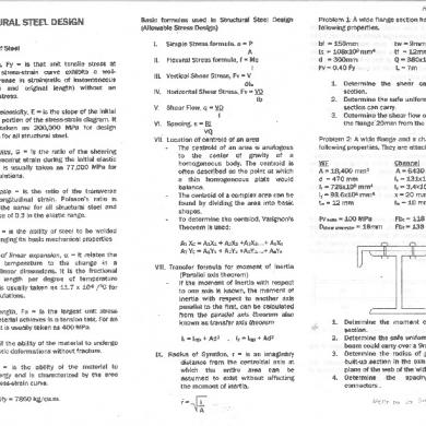
256436468-ri-ce-board-reviewer-steel.pdf
February 2021 0
Machine Design Board Exam Reviewer
February 2021 1
Mayorias Ce
January 2021 1More Documents from ""