A Pile Design
This document was uploaded by user and they confirmed that they have the permission to share it. If you are author or own the copyright of this book, please report to us by using this DMCA report form. Report DMCA
Overview
Download & View A Pile Design as PDF for free.
More details
- Words: 1,005
- Pages: 23
Loading documents preview...
By: VINEET GUPTA Sr. Prof./Bridges I
RELEVENT STANDARDS • Manual on the Design and Construction of well and pile Foundations issued by RDSO • IS 2911- Part I – Section I – Driven cast in situ piles – Section II- Bored cast in situ piles – Section III- Driven precast concrete piles
• IS 2911- Part IV- Load test
RELEVENT STANDARDS • Concrete Bridge code- For structural design • IRC- 78- For Road bridge foundations, can be referred for guidance
END BEARING PILE
FRICTION PILES
DRIVEN PILES
BORED PILING
STEPS OF DESIGN 1. 2. 3. 4. 5. 6. 7. 8.
From soil data, depth of scour – fix length of pile Base on thumb rules, fix dia of pile Calculate load carrying capacity of single pile using static formulae Do rough design for selected group of piles. Spacing to be based on thumb rules Check design for load carrying capacity, settlement, depth etc. Revise design if required Conduct load test to confirm capacity of pile Do structural design
BORED CAST IN SITU PILES ARE MOST COMMON FOR RAILWAY BRIDGES, SO FURTER DISCUSSION IS FOR BORED CAST IN SITU PILES ONLY
IMP. CODAL PROVISIONS •
DIA. OF PILE – Bridge Manual- > normally 1 m – IRC-78 » »
–
IS 2911- Part I, Section 2 »
•
Bored piles on land- min. 1 m Bored pile in river bridge- min. 1.2 m Provisions are for max. dia of 2.5 m
For Railway bridges dia. Of 1 m to 1.5 m be normally adopted
IMP. CODAL PROVISIONS •
•
SPACING OF PILE
–
IRC-78
–
IS 2911- Part I, Section 2
–
RDSO Manual
» »
Friction- min. 3 D End bearing- Can be reduced to clear distance= D that is c/c 2D
» » »
End bearing- hard soil- Min. 2.5 D End bearing- hard rock- Min. 2.0 D Friction- Min 3.0 D
» » »
Friction – min. 3 D End bearing- Min. 2.5 D Max. 4 D
For Railway bridges spacing of 2.5 D to 3.5D be normally adopted
IMP. CODAL PROVISIONS •
GROUP BEHAVIOR –
IRC-78 » » » »
–
IS 2911- Part I, Section 2 » »
–
End bearing- If spacing > 2.5 D, no reduction Friction- If spacing > 3 D, no reduction Check for block failure Settlement of group/single pile given for different width of group/pile dia Bored piles- end bearing- No reduction Other cases – descriptive guidelines given
RDSO Manual » » »
Dense sand not underlying by weak soil – driven pile – No reduction Loose sand soil – 50% reduction Sand not underlying by weak soil – boredreduction 33%
IMP. CODAL PROVISIONS •
PILE CAP
– IRC-78 » » »
Min. thickness 0.6 m or 1.5 m whichever is less Minimum offset of 150 mm beyond outer face Pile to project 50 mm into pile cap
–
IS 2911- Part I, Section 2
–
RDSO Manual
» » » »
»
Offset of 100-150 mm beyond outer face Pile to project 50 mm into pile cap Should be rigid enough Can be designed by taking dispersion at 45 degrees both from substructure and pile upto centre line NIL
IMP. CODAL PROVISIONS •
CONCRETE AND STEEL
–
IRC-78 » »
–
»
IS 2911- Part I, Section 2 » »
–
M 35, Min. cement 400 kg/m3, Max. W/C ratio 0.4, slump 50mm (150-200 for tremie) Min. long reinforcement 0.4%, links min. 8 mm @ 150 mm c/c. Min cover 75 mm.
»
M 20, Min. cement 400 kg/m3, 10% extra cement when under water, slump 100- 180 mm (150-180 for tremie) Min. long reinforcement 0.4%, Min. spacing 100mm, links min 6 mm @ 150 mm c/c. Min cover 40 mm.
RDSO Manual » »
NIL CBC to be followed based on enviornmental condition
IMP. CODAL PROVISIONS • FOS – IRC-78 » 2.5 if derived from static formulae for soil. 5 for end bearing on rock and 10 for socket resistance.
– IS 2911- Part I, Section 2 » Appendix given for calculating strength with static formulae
– RDSO Manual » 3 if derived from static formulae. » 2 if derived from load test
Factor of safety DEPENDS UPON •
Reliability of the soil parameters – • • •
•
Soil Type Spatial variability of the Soil – Uniform or Erratic The soil exploration programme – Average or Extensive
Method of construction, inspection and quality control
•
The factor of safety based on load Test shall be increased in following unfavorable conditions:a) Settlement is to be limited or unequal settlement avoided b) Large impact or vibrating loads are expected c) The properties of the soil are expected to deteriorate with time • The maximum permissible increase over the safe load of a pile on account of wind load is 25%
BORED CAST IN SITU PILES • ALIGNMENT CONTROL • For pile group_ – FOR VERTICAL PILES A DEVIATION OF NOT MORE THAN 1.5 % – FOR RAKER PILES A DEVIATION OF NOT MORE THAN 4 % – PILE SHOULD NOT SHIFT MORE THAN 75 MM OR D/4 WHICHEVER IS LESS ( FOR PILES LESS THAN OR EQUAL TO 600 MM DIA. ) – 75 MM OR D/10 WHICHEVER IS MORE FOR PILES MORE THAN 600 MM. DIA. PILE
LOAD CARRYING CAPACITY •
APPENDIX B - sandy soil
•Similar details for clayey soil is also there in APPENDIX B
DEPTH OF FIXITY •
Amendment 3 of IS code, Appendix C
•
Determine “T”
•
K1 given in table1, use submerged value varying from 0.146 for loose sand to 1.245 for dense sand Q
•
• •
Read L1/T v/s Lf/T fro fig 2 L1 is depth of scour Le should be more than 4R/4T Calculate BM and shear force after applying correction factor as per fig. 3
L1 Lf
Le
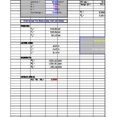
DESIGN EXAMPLE
References for further study • Theory & Practice of Foundation Design by Som N.N. and Das S.C. • Foundation Design & Construction by Tomlinson M.J. • Foundation Design – Theory and Practice by Coduto.
RELEVENT STANDARDS • Manual on the Design and Construction of well and pile Foundations issued by RDSO • IS 2911- Part I – Section I – Driven cast in situ piles – Section II- Bored cast in situ piles – Section III- Driven precast concrete piles
• IS 2911- Part IV- Load test
RELEVENT STANDARDS • Concrete Bridge code- For structural design • IRC- 78- For Road bridge foundations, can be referred for guidance
END BEARING PILE
FRICTION PILES
DRIVEN PILES
BORED PILING
STEPS OF DESIGN 1. 2. 3. 4. 5. 6. 7. 8.
From soil data, depth of scour – fix length of pile Base on thumb rules, fix dia of pile Calculate load carrying capacity of single pile using static formulae Do rough design for selected group of piles. Spacing to be based on thumb rules Check design for load carrying capacity, settlement, depth etc. Revise design if required Conduct load test to confirm capacity of pile Do structural design
BORED CAST IN SITU PILES ARE MOST COMMON FOR RAILWAY BRIDGES, SO FURTER DISCUSSION IS FOR BORED CAST IN SITU PILES ONLY
IMP. CODAL PROVISIONS •
DIA. OF PILE – Bridge Manual- > normally 1 m – IRC-78 » »
–
IS 2911- Part I, Section 2 »
•
Bored piles on land- min. 1 m Bored pile in river bridge- min. 1.2 m Provisions are for max. dia of 2.5 m
For Railway bridges dia. Of 1 m to 1.5 m be normally adopted
IMP. CODAL PROVISIONS •
•
SPACING OF PILE
–
IRC-78
–
IS 2911- Part I, Section 2
–
RDSO Manual
» »
Friction- min. 3 D End bearing- Can be reduced to clear distance= D that is c/c 2D
» » »
End bearing- hard soil- Min. 2.5 D End bearing- hard rock- Min. 2.0 D Friction- Min 3.0 D
» » »
Friction – min. 3 D End bearing- Min. 2.5 D Max. 4 D
For Railway bridges spacing of 2.5 D to 3.5D be normally adopted
IMP. CODAL PROVISIONS •
GROUP BEHAVIOR –
IRC-78 » » » »
–
IS 2911- Part I, Section 2 » »
–
End bearing- If spacing > 2.5 D, no reduction Friction- If spacing > 3 D, no reduction Check for block failure Settlement of group/single pile given for different width of group/pile dia Bored piles- end bearing- No reduction Other cases – descriptive guidelines given
RDSO Manual » » »
Dense sand not underlying by weak soil – driven pile – No reduction Loose sand soil – 50% reduction Sand not underlying by weak soil – boredreduction 33%
IMP. CODAL PROVISIONS •
PILE CAP
– IRC-78 » » »
Min. thickness 0.6 m or 1.5 m whichever is less Minimum offset of 150 mm beyond outer face Pile to project 50 mm into pile cap
–
IS 2911- Part I, Section 2
–
RDSO Manual
» » » »
»
Offset of 100-150 mm beyond outer face Pile to project 50 mm into pile cap Should be rigid enough Can be designed by taking dispersion at 45 degrees both from substructure and pile upto centre line NIL
IMP. CODAL PROVISIONS •
CONCRETE AND STEEL
–
IRC-78 » »
–
»
IS 2911- Part I, Section 2 » »
–
M 35, Min. cement 400 kg/m3, Max. W/C ratio 0.4, slump 50mm (150-200 for tremie) Min. long reinforcement 0.4%, links min. 8 mm @ 150 mm c/c. Min cover 75 mm.
»
M 20, Min. cement 400 kg/m3, 10% extra cement when under water, slump 100- 180 mm (150-180 for tremie) Min. long reinforcement 0.4%, Min. spacing 100mm, links min 6 mm @ 150 mm c/c. Min cover 40 mm.
RDSO Manual » »
NIL CBC to be followed based on enviornmental condition
IMP. CODAL PROVISIONS • FOS – IRC-78 » 2.5 if derived from static formulae for soil. 5 for end bearing on rock and 10 for socket resistance.
– IS 2911- Part I, Section 2 » Appendix given for calculating strength with static formulae
– RDSO Manual » 3 if derived from static formulae. » 2 if derived from load test
Factor of safety DEPENDS UPON •
Reliability of the soil parameters – • • •
•
Soil Type Spatial variability of the Soil – Uniform or Erratic The soil exploration programme – Average or Extensive
Method of construction, inspection and quality control
•
The factor of safety based on load Test shall be increased in following unfavorable conditions:a) Settlement is to be limited or unequal settlement avoided b) Large impact or vibrating loads are expected c) The properties of the soil are expected to deteriorate with time • The maximum permissible increase over the safe load of a pile on account of wind load is 25%
BORED CAST IN SITU PILES • ALIGNMENT CONTROL • For pile group_ – FOR VERTICAL PILES A DEVIATION OF NOT MORE THAN 1.5 % – FOR RAKER PILES A DEVIATION OF NOT MORE THAN 4 % – PILE SHOULD NOT SHIFT MORE THAN 75 MM OR D/4 WHICHEVER IS LESS ( FOR PILES LESS THAN OR EQUAL TO 600 MM DIA. ) – 75 MM OR D/10 WHICHEVER IS MORE FOR PILES MORE THAN 600 MM. DIA. PILE
LOAD CARRYING CAPACITY •
APPENDIX B - sandy soil
•Similar details for clayey soil is also there in APPENDIX B
DEPTH OF FIXITY •
Amendment 3 of IS code, Appendix C
•
Determine “T”
•
K1 given in table1, use submerged value varying from 0.146 for loose sand to 1.245 for dense sand Q
•
• •
Read L1/T v/s Lf/T fro fig 2 L1 is depth of scour Le should be more than 4R/4T Calculate BM and shear force after applying correction factor as per fig. 3
L1 Lf
Le
DESIGN EXAMPLE
References for further study • Theory & Practice of Foundation Design by Som N.N. and Das S.C. • Foundation Design & Construction by Tomlinson M.J. • Foundation Design – Theory and Practice by Coduto.
Related Documents

A Pile Design
January 2021 1
Design And Construction Of Driven Pile Foundation
February 2021 4
Sheet Pile
March 2021 0
Anchored Sheet Pile Wall Bs8002: 1994: Design Results
January 2021 0
Contoh Perhitungan Sheet Pile
January 2021 1More Documents from "Junaida Wally"

Plc,scada Training
February 2021 1
Cairn India Annual Report 2013-14
February 2021 0
Igc2 Workbook 2013.pdf
February 2021 1
A Pile Design
January 2021 1
Sharekhan Project
January 2021 3