Api Standard 19c
This document was uploaded by user and they confirmed that they have the permission to share it. If you are author or own the copyright of this book, please report to us by using this DMCA report form. Report DMCA
Overview
Download & View Api Standard 19c as PDF for free.
More details
- Words: 22,185
- Pages: 57
Loading documents preview...
Measurement of and Specifications for Proppants Used in Hydraulic Fracturing and Gravel-packing Operations
API STANDARD 19C SECOND EDITION, AUGUST 2018
--`,,,`,``,`,,`,``,,``,,`,`````,-`-`,,`,,`,`,,`---
Copyright American Petroleum Institute Provided by IHS Markit under license with API No reproduction or networking permitted without license from IHS
Licensee=PLUSPETROL - Lima 339/5967365004, User=Balda, Claudio Not for Resale, 10/16/2019 10:51:49 MDT
Special Notes
Neither API nor any of API's employees, subcontractors, consultants, committees, or other assignees make any warranty or representation, either express or implied, with respect to the accuracy, completeness, or usefulness of the information contained herein, or assume any liability or responsibility for any use, or the results of such use, of any information or process disclosed in this publication. Neither API nor any of API’s employees, subcontractors, consultants, or other assignees represent that use of this publication would not infringe upon privately owned rights. API publications may be used by anyone desiring to do so. Every effort has been made by the Institute to assure the accuracy and reliability of the data contained in them; however, the Institute makes no representation, warranty, or guarantee in connection with this publication and hereby expressly disclaims any liability or responsibility for loss or damage resulting from its use or for the violation of any authorities having jurisdiction with which this publication may conflict. API publications are published to facilitate the broad availability of proven, sound engineering and operating practices. These publications are not intended to obviate the need for applying sound engineering judgment regarding when and where these publications should be utilized. The formulation and publication of API publications is not intended in any way to inhibit anyone from using any other practices. Any manufacturer marking equipment or materials in conformance with the marking requirements of an API standard is solely responsible for complying with all the applicable requirements of that standard. API does not represent, warrant, or guarantee that such products do in fact conform to the applicable API standard.
All rights reserved. No part of this work may be reproduced, translated, stored in a retrieval system, or transmitted by any means, electronic, mechanical, photocopying, recording, or otherwise, without prior written permission from the publisher. Contact the Publisher, API Publishing Services, 1220 L Street, NW, Washington, DC 20005. Copyright © 2018 American Petroleum Institute
Copyright American Petroleum Institute Provided by IHS Markit under license with API No reproduction or networking permitted without license from IHS
Licensee=PLUSPETROL - Lima 339/5967365004, User=Balda, Claudio Not for Resale, 10/16/2019 10:51:49 MDT
--`,,,`,``,`,,`,``,,``,,`,`````,-`-`,,`,,`,`,,`---
API publications necessarily address problems of a general nature. With respect to particular circumstances, local, state, and federal laws and regulations should be reviewed.
Foreword Nothing contained in any API publication is to be construed as granting any right, by implication or otherwise, for the manufacture, sale, or use of any method, apparatus, or product covered by letters patent. Neither should anything contained in the publication be construed as insuring anyone against liability for infringement of letters patents. Shall: As used in a standard, “shall” denotes a minimum requirement in order to conform to the specification. Should: As used in a standard, “should” denotes a recommendation or that which is advised but not required in order to conform to the specification May: As used in a standard, “may” denotes a course of action permissible within the limits of a standard. Can: As used in a standard, “can” denotes a statement of possibility or capability. This document was produced under API standardization procedures that ensure appropriate notification and participation in the developmental process and is designated as an API standard. Questions concerning the interpretation of the content of this publication or comments and questions concerning the procedures under which this publication was developed should be directed in writing to the Director of Standards, American Petroleum Institute, 1220 L Street, NW, Washington, DC 20005. Requests for permission to reproduce or translate all or any part of the material published herein should also be addressed to the director. Generally, API standards are reviewed and revised, reaffirmed, or withdrawn at least every five years. A one-time extension of up to two years may be added to this review cycle. Status of the publication can be ascertained from the API Standards Department, telephone (202) 682-8000. A catalog of API publications and materials is published annually and updated quarterly by API, 1220 L Street, NW, Washington, DC 20005. Suggested revisions are invited and should be submitted to the Standards Department, API, 1220 L Street, NW, Washington, DC 20005, [email protected].
--`,,,`,``,`,,`,``,,``,,`,`````,-`-`,,`,,`,`,,
Copyright American Petroleum Institute Provided by IHS Markit under license with API No reproduction or networking permitted without license from IHS
iii Licensee=PLUSPETROL - Lima 339/5967365004, User=Balda, Claudio Not for Resale, 10/16/2019 10:51:49 MDT
--`,,,`,``,`,,`,``,,``,,`,`````,-`-`,,`,,`,`,,`---
Copyright American Petroleum Institute Provided by IHS Markit under license with API No reproduction or networking permitted without license from IHS
Licensee=PLUSPETROL - Lima 339/5967365004, User=Balda, Claudio Not for Resale, 10/16/2019 10:51:49 MDT
Contents Page
--`,,,`,``,`,,`,``,,``,,`,`````,-`-`,,`,,`,`,,`---
1
Scope . . . . . . . . . . . . . . . . . . . . . . . . . . . . . . . . . . . . . . . . . . . . . . . . . . . . . . . . . . . . . . . . . . . . . . . . . . . . . . . 1
2
Normative References . . . . . . . . . . . . . . . . . . . . . . . . . . . . . . . . . . . . . . . . . . . . . . . . . . . . . . . . . . . . . . . . . 1
3
Abbreviations . . . . . . . . . . . . . . . . . . . . . . . . . . . . . . . . . . . . . . . . . . . . . . . . . . . . . . . . . . . . . . . . . . . . . . . . 1
4 4.1 4.2 4.3 4.4 4.5 4.6
Standard Proppant Sampling Procedure . . . . . . . . . . . . . . . . . . . . . . . . . . . . . . . . . . . . . . . . . . . . . . . . . . General . . . . . . . . . . . . . . . . . . . . . . . . . . . . . . . . . . . . . . . . . . . . . . . . . . . . . . . . . . . . . . . . . . . . . . . . . . . . . . Particle Segregation . . . . . . . . . . . . . . . . . . . . . . . . . . . . . . . . . . . . . . . . . . . . . . . . . . . . . . . . . . . . . . . . . . . Equipment . . . . . . . . . . . . . . . . . . . . . . . . . . . . . . . . . . . . . . . . . . . . . . . . . . . . . . . . . . . . . . . . . . . . . . . . . . . Number of Required Samples-Bulk . . . . . . . . . . . . . . . . . . . . . . . . . . . . . . . . . . . . . . . . . . . . . . . . . . . . . . . Sampling-Bulk Material . . . . . . . . . . . . . . . . . . . . . . . . . . . . . . . . . . . . . . . . . . . . . . . . . . . . . . . . . . . . . . . . Sampling-Sacked and Bagged Material . . . . . . . . . . . . . . . . . . . . . . . . . . . . . . . . . . . . . . . . . . . . . . . . . . .
2 2 2 2 6 6 6
5 5.1 5.2 5.3
Sample Handling and Storage . . . . . . . . . . . . . . . . . . . . . . . . . . . . . . . . . . . . . . . . . . . . . . . . . . . . . . . . . . . Sample Reduction . . . . . . . . . . . . . . . . . . . . . . . . . . . . . . . . . . . . . . . . . . . . . . . . . . . . . . . . . . . . . . . . . . . . . Sample Splitting . . . . . . . . . . . . . . . . . . . . . . . . . . . . . . . . . . . . . . . . . . . . . . . . . . . . . . . . . . . . . . . . . . . . . . Sample, Record Retention, and Storage. . . . . . . . . . . . . . . . . . . . . . . . . . . . . . . . . . . . . . . . . . . . . . . . . . .
6 6 6 6
6 6.1 6.2 6.3 6.4 6.5 6.6
Sieve Analysis . . . . . . . . . . . . . . . . . . . . . . . . . . . . . . . . . . . . . . . . . . . . . . . . . . . . . . . . . . . . . . . . . . . . . . . . 7 Purpose . . . . . . . . . . . . . . . . . . . . . . . . . . . . . . . . . . . . . . . . . . . . . . . . . . . . . . . . . . . . . . . . . . . . . . . . . . . . . 7 Description . . . . . . . . . . . . . . . . . . . . . . . . . . . . . . . . . . . . . . . . . . . . . . . . . . . . . . . . . . . . . . . . . . . . . . . . . . 7 Apparatus and Materials . . . . . . . . . . . . . . . . . . . . . . . . . . . . . . . . . . . . . . . . . . . . . . . . . . . . . . . . . . . . . . . 7 Procedure . . . . . . . . . . . . . . . . . . . . . . . . . . . . . . . . . . . . . . . . . . . . . . . . . . . . . . . . . . . . . . . . . . . . . . . . . . . 8 Specifications-Sieve Analysis of Proppants . . . . . . . . . . . . . . . . . . . . . . . . . . . . . . . . . . . . . . . . . . . . . . . 9 Sieve Calibration . . . . . . . . . . . . . . . . . . . . . . . . . . . . . . . . . . . . . . . . . . . . . . . . . . . . . . . . . . . . . . . . . . . . . 13
7 7.1 7.2 7.3 7.4 7.5 7.6
Proppant Sphericity and Roundness . . . . . . . . . . . . . . . . . . . . . . . . . . . . . . . . . . . . . . . . . . . . . . . . . . . . Purpose . . . . . . . . . . . . . . . . . . . . . . . . . . . . . . . . . . . . . . . . . . . . . . . . . . . . . . . . . . . . . . . . . . . . . . . . . . . . Description . . . . . . . . . . . . . . . . . . . . . . . . . . . . . . . . . . . . . . . . . . . . . . . . . . . . . . . . . . . . . . . . . . . . . . . . . Apparatus Capability . . . . . . . . . . . . . . . . . . . . . . . . . . . . . . . . . . . . . . . . . . . . . . . . . . . . . . . . . . . . . . . . . Procedure . . . . . . . . . . . . . . . . . . . . . . . . . . . . . . . . . . . . . . . . . . . . . . . . . . . . . . . . . . . . . . . . . . . . . . . . . . Alternate Method for Determining Average Sphericity and Roundness . . . . . . . . . . . . . . . . . . . . . . . . Specifications-Proppant Roundness and Sphericity. . . . . . . . . . . . . . . . . . . . . . . . . . . . . . . . . . . . . . . .
16 16 16 17 17 18 18
8 8.1 8.2 8.3 8.4 8.5
Acid Solubility . . . . . . . . . . . . . . . . . . . . . . . . . . . . . . . . . . . . . . . . . . . . . . . . . . . . . . . . . . . . . . . . . . . . . . . Purpose . . . . . . . . . . . . . . . . . . . . . . . . . . . . . . . . . . . . . . . . . . . . . . . . . . . . . . . . . . . . . . . . . . . . . . . . . . . . Description . . . . . . . . . . . . . . . . . . . . . . . . . . . . . . . . . . . . . . . . . . . . . . . . . . . . . . . . . . . . . . . . . . . . . . . . . Apparatus and Materials . . . . . . . . . . . . . . . . . . . . . . . . . . . . . . . . . . . . . . . . . . . . . . . . . . . . . . . . . . . . . . Procedure . . . . . . . . . . . . . . . . . . . . . . . . . . . . . . . . . . . . . . . . . . . . . . . . . . . . . . . . . . . . . . . . . . . . . . . . . . Specifications-Acid Solubility . . . . . . . . . . . . . . . . . . . . . . . . . . . . . . . . . . . . . . . . . . . . . . . . . . . . . . . . . .
18 18 18 19 20 21
9 9.1 9.2 9.3 9.4 9.5 9.6
Turbidity . . . . . . . . . . . . . . . . . . . . . . . . . . . . . . . . . . . . . . . . . . . . . . . . . . . . . . . . . . . . . . . . . . . . . . . . . . . . Purpose . . . . . . . . . . . . . . . . . . . . . . . . . . . . . . . . . . . . . . . . . . . . . . . . . . . . . . . . . . . . . . . . . . . . . . . . . . . . Description . . . . . . . . . . . . . . . . . . . . . . . . . . . . . . . . . . . . . . . . . . . . . . . . . . . . . . . . . . . . . . . . . . . . . . . . . Apparatus and Materials . . . . . . . . . . . . . . . . . . . . . . . . . . . . . . . . . . . . . . . . . . . . . . . . . . . . . . . . . . . . . . Apparatus Calibration. . . . . . . . . . . . . . . . . . . . . . . . . . . . . . . . . . . . . . . . . . . . . . . . . . . . . . . . . . . . . . . . . Procedure-Turbidity Measurement . . . . . . . . . . . . . . . . . . . . . . . . . . . . . . . . . . . . . . . . . . . . . . . . . . . . . . Specification-Turbidity . . . . . . . . . . . . . . . . . . . . . . . . . . . . . . . . . . . . . . . . . . . . . . . . . . . . . . . . . . . . . . . .
21 21 21 22 22 22 22
10
Procedures for Determining Proppant Loose Pack Bulk Density, Apparent Density, and Absolute Density . . . . . . . . . . . . . . . . . . . . . . . . . . . . . . . . . . . . . . . . . . . . . . . . . . . . . . . . . . . . . . . . . 22 10.1 Purpose . . . . . . . . . . . . . . . . . . . . . . . . . . . . . . . . . . . . . . . . . . . . . . . . . . . . . . . . . . . . . . . . . . . . . . . . . . . . 22 v
Copyright American Petroleum Institute Provided by IHS Markit under license with API No reproduction or networking permitted without license from IHS
Licensee=PLUSPETROL - Lima 339/5967365004, User=Balda, Claudio Not for Resale, 10/16/2019 10:51:49 MDT
Contents Page
10.2 10.3 10.4 10.5
Description . . . . . . . . . . . . . . . . . . . . . . . . . . . . . . . . . . . . . . . . . . . . . . . . . . . . . . . . . . . . . . . . . . . . . . . . . Loose Pack Bulk density (ρbulk) . . . . . . . . . . . . . . . . . . . . . . . . . . . . . . . . . . . . . . . . . . . . . . . . . . . . . . . . Apparent Density (ρap) . . . . . . . . . . . . . . . . . . . . . . . . . . . . . . . . . . . . . . . . . . . . . . . . . . . . . . . . . . . . . . . . Absolute Density (ρabs) . . . . . . . . . . . . . . . . . . . . . . . . . . . . . . . . . . . . . . . . . . . . . . . . . . . . . . . . . . . . . . .
23 23 27 29
11 11.1 11.2 11.3 11.4 11.5 11.6 11.7 11.8
Proppant Crush Resistance . . . . . . . . . . . . . . . . . . . . . . . . . . . . . . . . . . . . . . . . . . . . . . . . . . . . . . . . . . . . Purpose . . . . . . . . . . . . . . . . . . . . . . . . . . . . . . . . . . . . . . . . . . . . . . . . . . . . . . . . . . . . . . . . . . . . . . . . . . . . Description . . . . . . . . . . . . . . . . . . . . . . . . . . . . . . . . . . . . . . . . . . . . . . . . . . . . . . . . . . . . . . . . . . . . . . . . . Apparatus . . . . . . . . . . . . . . . . . . . . . . . . . . . . . . . . . . . . . . . . . . . . . . . . . . . . . . . . . . . . . . . . . . . . . . . . . . Sample Preparation . . . . . . . . . . . . . . . . . . . . . . . . . . . . . . . . . . . . . . . . . . . . . . . . . . . . . . . . . . . . . . . . . . Assemble and Set Up the Crush Cell and Pluviator Loading Device. . . . . . . . . . . . . . . . . . . . . . . . . . . Procedure-Crush Resistance Testing . . . . . . . . . . . . . . . . . . . . . . . . . . . . . . . . . . . . . . . . . . . . . . . . . . . . Specification-Crush Resistance of Fracturing Proppants . . . . . . . . . . . . . . . . . . . . . . . . . . . . . . . . . . . Specification-Crush Resistance of Gravel-packing Proppants . . . . . . . . . . . . . . . . . . . . . . . . . . . . . . .
30 30 30 30 35 36 38 39 40
12 12.1 12.2 12.3
Loss on Ignition (LOI) of Whole Grain Proppant . . . . . . . . . . . . . . . . . . . . . . . . . . . . . . . . . . . . . . . . . . . Purpose . . . . . . . . . . . . . . . . . . . . . . . . . . . . . . . . . . . . . . . . . . . . . . . . . . . . . . . . . . . . . . . . . . . . . . . . . . . . Apparatus and Materials . . . . . . . . . . . . . . . . . . . . . . . . . . . . . . . . . . . . . . . . . . . . . . . . . . . . . . . . . . . . . . Procedure . . . . . . . . . . . . . . . . . . . . . . . . . . . . . . . . . . . . . . . . . . . . . . . . . . . . . . . . . . . . . . . . . . . . . . . . . .
41 41 41 41
Annex A (informative) ASTM E11 Sieve Table . . . . . . . . . . . . . . . . . . . . . . . . . . . . . . . . . . . . . . . . . . . . . . . . . . . . 44
Figures 1 Typical Box Sampling Device. . . . . . . . . . . . . . . . . . . . . . . . . . . . . . . . . . . . . . . . . . . . . . . . . . . . . . . . . . . . . . . 3 2 Typical 16:1 Sample Reducer. . . . . . . . . . . . . . . . . . . . . . . . . . . . . . . . . . . . . . . . . . . . . . . . . . . . . . . . . . . . . . . 4 3 Typical Sample Splitter . . . . . . . . . . . . . . . . . . . . . . . . . . . . . . . . . . . . . . . . . . . . . . . . . . . . . . . . . . . . . . . . . . . . 5 4 Graphical Method for Determination of Median Diameter . . . . . . . . . . . . . . . . . . . . . . . . . . . . . . . . . . . . . . 13 5 Chart for Visual Estimation of Sphericity and Roundness. . . . . . . . . . . . . . . . . . . . . . . . . . . . . . . . . . . . . . 17 6 Loose Pack Bulk Density Device. . . . . . . . . . . . . . . . . . . . . . . . . . . . . . . . . . . . . . . . . . . . . . . . . . . . . . . . . . . 24 7 Design of the Crush Cell. . . . . . . . . . . . . . . . . . . . . . . . . . . . . . . . . . . . . . . . . . . . . . . . . . . . . . . . . . . . . . . . . . 32 8 Assembled View of Pluviator Device . . . . . . . . . . . . . . . . . . . . . . . . . . . . . . . . . . . . . . . . . . . . . . . . . . . . . . . 33 9 Exploded View of Pluviator Device . . . . . . . . . . . . . . . . . . . . . . . . . . . . . . . . . . . . . . . . . . . . . . . . . . . . . . . . . 34 10 Dimensional View of the Pluviator Device . . . . . . . . . . . . . . . . . . . . . . . . . . . . . . . . . . . . . . . . . . . . . . . . . . . 35 Tables 1 ASTM Test Sieve Sizes . . . . . . . . . . . . . . . . . . . . . . . . . . . . . . . . . . . . . . . . . . . . . . . . . . . . . . . . . . . . . . . . . . . . 7 2 Example Sieve Analysis and Calculations (Fracturing 16/30 Proppant). . . . . . . . . . . . . . . . . . . . . . . . . . . 10 3 Example Calculation of Median Diameter (Fracturing 16/30 Proppant) . . . . . . . . . . . . . . . . . . . . . . . . . . . 12 4 Example of Absolute Relative Difference Calculations . . . . . . . . . . . . . . . . . . . . . . . . . . . . . . . . . . . . . . . . 16 5 Suggested Magnification . . . . . . . . . . . . . . . . . . . . . . . . . . . . . . . . . . . . . . . . . . . . . . . . . . . . . . . . . . . . . . . . . 18 6 Proppant Maximum Acid Solubility . . . . . . . . . . . . . . . . . . . . . . . . . . . . . . . . . . . . . . . . . . . . . . . . . . . . . . . . . 21 7 Density of Water at Various Temperatures . . . . . . . . . . . . . . . . . . . . . . . . . . . . . . . . . . . . . . . . . . . . . . . . . . . 26 8 Pluviator Cell Loading Device, Parts, and Accessories . . . . . . . . . . . . . . . . . . . . . . . . . . . . . . . . . . . . . . . . 33 9 Wire Cloth Sizes Used in the Pluviator Device . . . . . . . . . . . . . . . . . . . . . . . . . . . . . . . . . . . . . . . . . . . . . . . 37 10 Guidelines for Testing Various Proppant Types . . . . . . . . . . . . . . . . . . . . . . . . . . . . . . . . . . . . . . . . . . . . . . 38 11 10 % Crush Classification Table for Fracturing Proppants . . . . . . . . . . . . . . . . . . . . . . . . . . . . . . . . . . . . . 40 12 Maximum Fines for Gravel-packing Proppant . . . . . . . . . . . . . . . . . . . . . . . . . . . . . . . . . . . . . . . . . . . . . . . . 41
vi Copyright American Petroleum Institute Provided by IHS Markit under license with API No reproduction or networking permitted without license from IHS
Licensee=PLUSPETROL - Lima 339/5967365004, User=Balda, Claudio Not for Resale, 10/16/2019 10:51:49 MDT
--`,,,`,``,`,,`,``,,``,,`,`````,-`-`,,`,,`,`,,`---
Bibliography . . . . . . . . . . . . . . . . . . . . . . . . . . . . . . . . . . . . . . . . . . . . . . . . . . . . . . . . . . . . . . . . . . . . . . . . . . . . . . . . 47
--`,,,`,``,`,,`,``,,``,,`,`````,-`-`,,`,,`,`,,`---
Copyright American Petroleum Institute Provided by IHS Markit under license with API No reproduction or networking permitted without license from IHS
Licensee=PLUSPETROL - Lima 339/5967365004, User=Balda, Claudio Not for Resale, 10/16/2019 10:51:49 MDT
The procedures presented in this document have been developed to improve the quality of proppants delivered to the well site. They are for use in evaluating certain physical properties used in hydraulic fracturing and gravel-packing operations. These tests should enable users to compare the physical characteristics of various proppants tested under the described conditions and to select materials useful for hydraulic fracturing and gravel-packing operations. Each section contains proppant specifications and replaces API 19C, First Edition. The procedures presented in this document are not intended to inhibit the development of new technology, material improvements, and improved operational procedures. Qualified engineering analysis and judgment are required for their application to a specific situation. As with any laboratory procedure requiring the use of potentially hazardous chemicals and equipment, the user is expected to have received proper training and knowledge in the use and disposal of these potentially hazardous materials. The user is responsible for compliance with all applicable local, regional, and national requirements for worker and local health, safety, and environmental liability. This document uses a format for numbers that follows the examples given in API Document Format and Style Manual, First Edition, June 2007 (Editorial Revision, January 2009). This numbering format is different than that used in API 19C, Second Edition. In this document, the decimal mark is a period and separates the whole part from the fractional part of a number. No spaces are used in the numbering format. The thousands separator is a comma and is only used for numbers greater than 10,000, i.e. 5000 items, 12,500 bags. In this document, where practical, U.S. Customary units are included in parentheses for information. The units do not necessarily represent a direct conversion of metric units (SI) to U.S. Customary units, or U.S. Customary to SI. Consideration has been given to the precision of the instrument making the measurement. Consideration has also been given to the nature of the measurement, determining if it is critical or simply informational. The document was originally based on API RP 56, API RP 58, and API RP 60, which are no longer in effect.
Copyright American Petroleum Institute Provided by IHS Markit under license with API No reproduction or networking permitted without license from IHS
Licensee=PLUSPETROL - Lima 339/5967365004, User=Balda, Claudio Not for Resale, 10/16/2019 10:51:49 MDT
--`,,,`,``,`,,`,``,,``,,`,`````,-`-`,,`,,`,`,,`---
Introduction
Measurement of and Specifications for Proppants Used in Hydraulic Fracturing and Gravel-packing Operations 1
Scope
This document provides specifications and standard testing procedures for evaluating proppants used in hydraulic fracturing and gravel-packing operations. The objective of this document is to provide specifications and a consistent methodology for testing performed on hydraulic fracturing and/or gravel-packing proppants. Methodologies and specifications (where applicable) are provided for: — sieve analysis and median diameter determination; — sphericity and roundness; — acid solubility; — turbidity; — loose pack bulk density, apparent density, and absolute density; — crush resistance; — loss on ignition. Proppant size designation is as per industry standard. It is based on the maximum and minimum size determination by sieve analysis and ASTM 1 sieve number (and not as per standard opening expressed in micrometers). Proppants in this document are sand, ceramic media, resin-coated proppants, gravel-packing media, and other similarly used materials for hydraulic fracturing and gravel-packing operations.
2
Normative References
The following referenced documents are indispensable for the application of this document. For dated reference, only the edition cited applies. For undated references, the latest edition of the referenced document (including any amendments) applies. ASTM E11, Standard Specification for Woven Wire Test Sieve Cloth and Test Sieves
3
Abbreviations
ANSI 2 American National Standards Institute API
American Petroleum Institute
1 ASTM International, 100 Barr Harbor Drive, West Conshohocken, PA 19428-2959, www.astm.org 2 ANSI (Operations), 25 West 43rd Street, 4th Floor, New York, NY 10036, www.ansi.org --`,,,`,``,`,,`,``,,``,,`,`````,-`-`,,`,,`,`,,`---
Copyright American Petroleum Institute Provided by IHS Markit under license with API No reproduction or networking permitted without license from IHS
Licensee=PLUSPETROL - Lima 339/5967365004, User=Balda, Claudio Not for Resale, 10/16/2019 10:51:49 MDT
2
API STANDARD 19C
ASTM American Society for Testing and Materials FTU
Formazin turbidity unit
LOI
loss on ignition
NTU
nephelometric turbidity unit
4
Standard Proppant Sampling Procedure
4.1
General
Before any sample is taken, consider what tests will be performed; each test will require different volumes. It is important that both the supplier and customer obtain the best representative sample possible. Unless the sample is truly representative of a total shipment or container, testing and correlation with specifications/standards is difficult. It is unlikely that sampling/testing methods in the field duplicate the producer’s system. The standard procedures included within this document assist in obtaining representative samples; however, there are inherent variations associated with sampling, testing equipment, and procedures that can lead to inconsistent results. A sample that is representative of a truckload, 23,000 kg (50,700 lb), or a railcar load, 90,000 kg (198,000 lb), can be the initial source of wide variation when making comparisons. All parties shall ensure uniform samples. The customer and supplier shall agree on sampling and testing methods/techniques. For the best representation, continuous sampling is ideal. Although many proppant suppliers utilize automatic sampling, it is usually impractical at the job site. If sampling is conducted while unloading a container or at the well site, consideration should be given to the number and frequency of samples. If bulk containers are filled from a flowing stream of proppant material, sampling procedures in accordance with 4.5 shall be applied. If bulk containers are filled using sacked proppant material, sampling procedures in accordance with 4.6 shall be applied.
4.2
Particle Segregation
It is important to have a basic understanding of segregation when sampling proppant. Depending on the size, shape, distribution, and mechanisms involved, there is usually a certain amount of error or variability involved in sampling due to segregation. The sampling procedures described here are the result of much experience and are designed to minimize the effects of segregation of particles by size. --`,,,`,``,`,,`,``,,``,,`,`````,-`-`,,`,,`,`,,`---
Particles, such as proppants, will naturally find the path of least resistance when moved or when force is applied. During transfer or movement, particles of differing size and mass naturally separate or segregate. The degree of segregation depends on the mechanisms involved in the transfer or movement. There are several forces, such as gravity, acting on a stream of particles as it flows. Within a moving stream, fine particles drop through the voids or gaps and coarser particles move to the outside. The fine particles migrate and usually rest close to the area where they land. The heavier, coarser particles bounce or roll much further, stratifying the material by particle size.
4.3
Equipment
The following equipment shall be used to compile representative proppant material samples. 4.3.1
Sampling Device
With a minimum slot opening six times the largest particle diameter sampled. For example, a 12/20 fracturing proppant may contain particles as large as 2.36 mm, the size of the opening in a U.S. alternative No. 8 (ASTM 2.36 mm) test sieve. Copyright American Petroleum Institute Provided by IHS Markit under license with API No reproduction or networking permitted without license from IHS
Licensee=PLUSPETROL - Lima 339/5967365004, User=Balda, Claudio Not for Resale, 10/16/2019 10:51:49 MDT
MEASUREMENT OF AND SPECIFICATIONS FOR PROPPANTS USED IN HYDRAULIC FRACTURING AND GRAVEL-PACKING OPERATIONS
3
The minimum slot opening is defined as: 6 x 2.36 mm = 14.2 mm or 0.557 in. The length of the slot shall be longer than the thickness of the stream being sampled. The volume of the sampler shall be large enough so as to not overflow while cutting through the entire stream. An example of a sampling device is shown in Figure 1.
Key 1 2 3 4
Sampler body: aluminum; 160 mm x 210 mm x 65 mm (6.25 in. x 8.25 in. x 2.5 in.) Handle: common round pipe of sufficient strength to support the sampler plus about 1.6 kg (3.5 lb) proppant; length as needed Pipe coupling to accept handle (two locations) Sample opening: 15 mm (0.6 in.)
--`,,,`,``,`,,`,``,,``,,`,`````,-`-`,,`,,`,`,,`---
Figure 1—Typical Box Sampling Device
Copyright American Petroleum Institute Provided by IHS Markit under license with API No reproduction or networking permitted without license from IHS
Licensee=PLUSPETROL - Lima 339/5967365004, User=Balda, Claudio Not for Resale, 10/16/2019 10:51:49 MDT
4
API STANDARD 19C
4.3.2
Sample Reducer (16:1)
Of appropriate size for handling sack-size samples and reducing the material to 1/16 of the original mass. See Figure 2.
Key 1 2 3 4 5 6 7 8
Main body: 370 mm x 480 mm x 110 mm (14.5 in. x 19 in. x 4.5 in.) Splitter plate: eight locations, 51 mm x 51 mm x 51 mm (2 in. x 2 in. x 2 in.) Discharge plate: 370 mm x 300 mm x 3.2 mm (14.5 in. x 12 in. x 0.125 in.) Discharge chute: 57 mm x 57 mm x 76 mm (2.25 in. x 2.25 in. x 3 in.) Hopper: 370 mm x 240 mm x 150 mm (14.5 in. x 9.5 in. x 6 in.) Gate: 370 mm x 190 mm x 3.5 mm (14.5 in. x 7.5 in. x 0.125 in.) Hand knob: diameter 38 mm (1.5 in.) Support stand assembly: 710 mm x 380 mm x 690 mm (28 in. x 15 in. x 27 in.)
Figure 2— Typical 16:1 Sample Reducer
--`,,,`,``,`,,`,``,,``,,`,`````,-`
Copyright American Petroleum Institute Provided by IHS Markit under license with API No reproduction or networking permitted without license from IHS
Licensee=PLUSPETROL - Lima 339/5967365004, User=Balda, Claudio Not for Resale, 10/16/2019 10:51:49 MDT
MEASUREMENT OF AND SPECIFICATIONS FOR PROPPANTS USED IN HYDRAULIC FRACTURING AND GRAVEL-PACKING OPERATIONS
4.3.3
Sample Splitter
Of appropriate size.
Key 1 2 3 4 5 6
Main body: 290 mm x 280 mm x 165 mm (11.5 in. x 11 in. x 6.5 in.) Handle Gate plate Hopper Pan Splitter vanes: 16 locations, 15 mm (0.6 in.)
Figure 3—Typical Sample Splitter
--`,,,`,``,`,,`,``,,``,,`,`````,-`-`,,`,,`,`,,`---
Copyright American Petroleum Institute Provided by IHS Markit under license with API No reproduction or networking permitted without license from IHS
Licensee=PLUSPETROL - Lima 339/5967365004, User=Balda, Claudio Not for Resale, 10/16/2019 10:51:49 MDT
5
6
API STANDARD 19C
4.4
Number of Required Samples—Bulk
4.4.1
Proppants for Hydraulic Fracturing
A minimum of one sample per 9000 kg (20,000 lb), or fraction thereof, shall be obtained. All samples per bulk container shall be combined and tested. 4.4.2
Gravel-packing Proppant
A minimum of one sample per 4500 kg (10,000 lb), but no fewer than two samples per job, shall be obtained, combined, and tested.
4.5
Sampling—Bulk Material
All samples shall be obtained from a flowing stream of proppant by a manual or automatic sampler. Samples shall not be taken from a static pile. The sampling device shall be used with its length perpendicular to the flowing proppant stream. The sampler shall be passed at a uniform rate from side to side through the full stream width of moving proppant. This shall be done as the material is moving to or from a conveyor belt into a blender, truck, railcar, or bulk container. Approximately 2000 kg (4400 lb) of proppant material shall be allowed to flow prior to taking the first sample. The number of samples taken shall comply with 4.4. During sampling, the sampling receptacle shall be passed completely across the moving proppant stream in a brief interval of time so as to sample the entire stream with each pass. Under no circumstances shall the sampling receptacle be allowed to overflow.
4.6
Sampling—Sacked and Bagged Material
4.6.1
Sacks Up to 50 kg (110 lb)
Only whole sacks are to be used for sampling proppant materials. 4.6.2
Totes/Bulk Bags/Super Sacks: Weighting up to 2000 kg (4400 lb)
Unless the product can be sampled in a free-flowing state, the sample of large bags presents the same problems as a static pile. Follow the same sample frequency as described in 4.4, using the sampling method described in 4.5, but allow approximately 50 kg (110 lb) to be discharged from the bulk bag before sampling.
5 5.1
Sample Handling and Storage Sample Reduction
Place the contents of the combined bulk sample of proppant, or an entire sack up to 50 kg (110 lb), in the 16:1 sample reducer (see Figure 2) or equivalent. Obtain a reduced sample of approximately 1/16 of the original mass of the total sack’s contents, typically 3 kg (6.6 lb).
5.2
Sample Splitting
An appropriately sized sample reducer and sample splitter shall be used to prepare representative samples for testing. Place the reduced sample, obtained according to 5.1, or the sample obtained during bulk material loading operations (refer to 4.5) in the sample splitter (see Figure 3) or equivalent. Split the sample to the desired quantity to permit performance tests as specified in this document.
5.3
Sample, Record Retention, and Storage
The proppant supplier shall maintain records of all tests conducted on each shipment for a minimum of one year. Physical samples of an amount sufficient to conduct all tests recommended herein, but in no --`,,,`,``,`,,`,``,,``,,`,`````,-`-`,,`,,`,`,,`---
Copyright American Petroleum Institute Provided by IHS Markit under license with API No reproduction or networking permitted without license from IHS
Licensee=PLUSPETROL - Lima 339/5967365004, User=Balda, Claudio Not for Resale, 10/16/2019 10:51:49 MDT
MEASUREMENT OF AND SPECIFICATIONS FOR PROPPANTS USED IN HYDRAULIC FRACTURING AND GRAVEL-PACKING OPERATIONS
7
cases less than 0.25 kg (0.5 lb), shall be retained in storage for a minimum of six months. Any material subsequently taken for testing shall be split from the retained sample. Samples shall be sealed in a type of container that is sufficient to protect the sample from contamination and moisture. Samples shall be stored in a cool, dry place.
6
Sieve Analysis
6.1
Purpose
The purpose of this section is to provide specifications for recognized proppant sizes and a standard procedure to ensure a consistent methodology for sieve analysis.
6.2
Description
The procedure and equipment described in 6.3 through 6.6 are the most widely utilized in the hydraulic fracturing and gravel-packing industry. Alternate methods may be used, but shall be correlated with these standard methods.
6.3 6.3.1
Apparatus and Materials Sieve Sets (Two)
Complying with the requirement of ASTM Sieve Series, 200 mm (8 in.) diameter or equivalent. One set is a working or compliance set, and the other a master or calibration set to be used for calibration or standardization only. Compliance and calibration sieves are defined in ASTM E11. NOTE
For informational purposes, an excerpt from E11 is included in this document as Annex A.
Table 1—ASTM Test Sieve Sizes Sieve-opening Sizes µm 3350/ 1700
2360/ 1180
1700/ 1000
1700/ 850
1180/ 850
1180/ 600
850/ 425
600/ 300
425/ 250
425/ 212
212/ 106
20/40
30/50
40/60
40/70
70/140
6/12
8/16
12/18
12/20
16/20
16/30
Stack of ASTM Sieves a,b Upper designating sieve in bold type
Lower designating sieve in bold type
4
6
8
8
12
12
16
20
30
30
50
6
8
12
12
16
16
20
30
40
40
70
8
10
14
14
18
18
25
35
45
45
80
10
12
16
16
20
20
30
40
50
50
100
12
14
18
18
25
25
35
45
60
60
120
14
16
20
20
30
30
40
50
70
70
140
16
20
30
30
40
40
50
70
100
100
200
pan
pan
pan
pan
pan
pan
pan
pan
pan
pan
pan
a Sieve series as defined in ASTM E11 (U.S. Alternative designation); refer to Annex A for opening size in µm. b Test sieve stacked in order from top to bottom, largest opening on top.
Copyright American Petroleum Institute Provided by IHS Markit under license with API No reproduction or networking permitted without license from IHS
Licensee=PLUSPETROL - Lima 339/5967365004, User=Balda, Claudio Not for Resale, 10/16/2019 10:51:49 MDT
--`,,,`,``,`,,`,``,,``,,`,`````,-`-`,,`,,`,`,,`---
Typical Proppant/Gravel-pack Size Designations
8
6.3.2
API STANDARD 19C
Testing Sieve Shaker
To provide simultaneous rotating and tapping action, and accept the sieves specified in Table 1. To mitigate the effect of static charge, the stack of sieves should be grounded. The preferred shaker will have performance characteristics as follows: — oscillations per minute: 278 ±10 — oscillation displacement: 28.6 ±11.1 mm (1.125 in. ±0.4375 in.) — taps per minute: 150 ±10 — height of the tapper: 33.3 ±1.6 mm (1.3125 in. ±0.0625 in.) — hammer weight: 2.44 kg (5.38 lb) — timer accuracy: ±5 seconds over a 10-minute interval 6.3.3
Balance
Minimum capacity of 100 g with precision of 0.01 g or better. 6.3.4
Brushes
Nylon or equivalent.
6.4
Procedure
6.4.1 Stack a minimum of seven sieves, checked against a master set, plus a pan and cover, in a stack of decreasing sieve opening sizes from top to bottom. Table 1 establishes sieve sizes for use in testing designated example proppant sizes. Table 1 should be used as a guide and does not attempt to preclude the use of other grades that are or may become available. 6.4.2
Weigh each clean sieve and record the mass.
6.4.3 Using a split sample of 100 g ±20 g, obtain an accurate initial mass, minit, and record the mass to the nearest 0.01 g. 6.4.4 Pour the split and weighed sample onto the top sieve. Place the stack of sieves plus the pan and lid in the test sieve shaker and shake for 10 minutes ±5 seconds. --`,,,`,``,`,,`,``,,``,,`,`````,-`-`,,`,,`,`,,`---
6.4.5
Remove the sieve stack from the test sieve shaker.
6.4.6 Weigh each sieve with the proppant. Invert the sieve on a collection device and remove the proppant by thoroughly brushing the sieve to ensure that grains are not adhering to the wire cloth. Calculate the mass retained by subtracting the empty sieve mass from the sieve plus proppant mass. Record the mass of proppant retained on each of the sieves and the pan, mi. 6.4.7 The cumulative mass shall be within 0.5 % of the initial sample mass, minit, used in the test. If not, the sieve analysis shall be repeated using a different sample. 6.4.8 Calculate the percent by mass or frequency, ni, of the total proppant sample retained on each sieve and in the pan using Equation (1).
Copyright American Petroleum Institute Provided by IHS Markit under license with API No reproduction or networking permitted without license from IHS
Licensee=PLUSPETROL - Lima 339/5967365004, User=Balda, Claudio Not for Resale, 10/16/2019 10:51:49 MDT
MEASUREMENT OF AND SPECIFICATIONS FOR PROPPANTS USED IN HYDRAULIC FRACTURING AND GRAVEL-PACKING OPERATIONS
= ni 100 ×
mi ∑ mi
9
(1)
where
6.5 6.5.1
mi
is the measured mass of proppant retained on the sieve of interest, expressed in grams
Σmi
is the sum of each of the measured masses retained on the sieves and pan, expressed in grams
Specifications—Sieve Analysis of Proppants Fracturing Proppant Sizes
A minimum of 90.0 % of the tested proppant sample shall pass through the coarse designated sieve and be retained on or above the fine designated sieve, i.e. 12/20, 20/40, 40/70. Not over 0.1 % of the total tested proppant sample shall be larger than the first sieve in the stack specified in Table 1, and not over 1.0 % of the total tested proppant sample shall be retained in the pan. For example, a 20/40 proppant sample shall have no more than 0.1 % of the total tested proppant sample retained on the No. 16 sieve and no more than 1.0 % of the total tested proppant sample shall be retained in the pan. The median diameter, d50, and the particle size distribution of each grade shall be made available. 6.5.2
Gravel-packing Proppant Sizes
A minimum of 96.0 % of the tested proppant sample shall pass the coarse designated sieve and be retained on the fine designated sieve, i.e. 12/20, 20/40, 40/60. Not over 0.1 % of the total tested proppant sample shall be larger than the first/top sieve in the stack specified in Table 1, and not over 1.0 % of the total tested proppant shall be smaller than the last designated sieve size. For example, a 20/40 proppant sample shall have no more than 0.1 % of the total tested sample retained on the No. 16 sieve and no more than 1.0 % of the total tested sample shall be retained in the pan. The median diameter, d50, and the particle size distribution of each grade shall be made available. 6.5.3
Example Sieve Analysis and Calculations
In Table 2, the first column is a listing of the sieve numbers used to test a sample of 16/30 sand. The numbers and labels are lifted directly from Table 1. — Column 2 is the position of each sieve in the stack or nest assembled before testing begins. The largest holes (smallest sieve number) are on the top of the stack, position 1, with the other sieves below in sequence: smallest sieve number down to the largest sieve number, then the pan at the bottom of the nest, position 8. — Column 3 is the specification listed next to the appropriate sieves or labels. — Column 4 shows the proppant mass retained on each of the sieves and the pan. — Column 5 shows the result of calculating the weight percent retained for each of the sieves and the pan. — Column 6 shows the cumulative percent retained numbers.
--`,,,`,``,`,,`,``,,``,,`,`````,-`-`,,`,,`,`,,`---
Copyright American Petroleum Institute Provided by IHS Markit under license with API No reproduction or networking permitted without license from IHS
Licensee=PLUSPETROL - Lima 339/5967365004, User=Balda, Claudio Not for Resale, 10/16/2019 10:51:49 MDT
10
API STANDARD 19C
Table 2—Example Sieve Analysis and Calculations (Fracturing 16/30 Proppant) ASTM Sieve Series U.S. Alternative Sieve Number (opening size)
Sieve in Stack Position
Specification % by mass
Mass Retained mi g
Mass Retained or Frequency ni % by mass
Cumulative Mass Retained % by mass
< 0.1
0.00
0.0
0.0
i
12
(1.7 mm)
1 (top)
16
(1.18 mm)
2
1.20
1.19
1.2
18
(1.0 mm)
3
37.90
37.63
38.8
20
(850 µm)
4
48.70
48.36
87.2
25
(710 µm)
5
11.90
11.82
99.0
30
(600 µm)
6
0.30
0.30
99.3
40
(425 µm)
7
0.20
0.20
99.5
0.50
0.50
100.0
100.70
100.0
Pan
8 (bottom)
> 90.0
> 1.0
Total Initial Mass, minit, g
80 to 120 g
100.50
Difference
< 0.5
–0.20
In-size
> 90.0
–0.2 98.1
The bottom rows of Table 2, beginning with the row labeled “total,” are various calculations used to evaluate the sieve analysis results against the specifications. It is helpful to the observer that the results related to each of the five specifications for sieve analysis are in bold font with bold cell margins. — The first specification is the initial sample mass and is recorded in column 4, opposite the label “Initial Mass, minit, g.” — The second specification is the difference between the initial sample mass, minit, and the sum of all the retained masses, and is recorded in column 5 opposite the label “Difference.” The negative number –0.2 % is within specification and indicates that a small amount of proppant was picked up from material left in the sieves or handling equipment from the last time it was used. — The third specification is the amount of material retained on the top sieve and is recorded in column 5 opposite the No.12 sieve. Note that 0.0 % is less than 0.1 % and is within specification. — The fourth specification is the mass of proppant retained in the pan and is recorded in column 5 opposite the label “Pan.” Note that 0.5 % is less than 1.0 % and is within specification. --`,,,`,``,`,,`,``,,``,,`,`````,-`-`,,`,,`,`,,`---
— The fifth and last specification is the mass of proppant considered to be “in-size.” In this case, the cumulative mass of proppant passing through the No. 16 sieve and retained on the No. 30 sieve is calculated and recorded in column 5 opposite the label “In-size.” Note that 98.1 % is greater than the 90 % and is within specification.
Copyright American Petroleum Institute Provided by IHS Markit under license with API No reproduction or networking permitted without license from IHS
Licensee=PLUSPETROL - Lima 339/5967365004, User=Balda, Claudio Not for Resale, 10/16/2019 10:51:49 MDT
MEASUREMENT OF AND SPECIFICATIONS FOR PROPPANTS USED IN HYDRAULIC FRACTURING AND GRAVEL-PACKING OPERATIONS
11
Since each of the five specification items passes the limitations required by this section, the sample of 16/30 sand has the properties of an acceptable 16/30 fracturing proppant with respect to particle size distribution. 6.5.4
Proppant Median Diameter, d50
The median diameter, d50, is used to characterize proppant size distribution for hydraulic fracturing and gravel-packing and is derived from the particle size characterization or sieve analysis described in 6.4, and reported in addition to that analysis. In gravel-packing, the median diameter, d50, the 50th mass percentile, is commonly used to evaluate the suitability of gravel to retain formation sand. In hydraulic fracturing, this same value is used to predict long-term conductivity performance, as well as other properties directly related to demonstrable flow capacity or potential productivity of the well. Both disciplines calculate the number as follows: Calculating Median Diameter, d50
6.5.4.1
The sieve analysis obtained in 6.4 and demonstrated in Table 2 is repeated for clarity in Table 3, columns 1, 5, and 6 for the 16/30 proppant. The cumulative percent of the material retained by all the sieves and the pan should be 100 %. Refer to Table 3, column 6. The median diameter is calculated using a variable called phi, Φi, calculated in column 7 of Table 3, using Equation (2) as one-half the difference in the negative logarithm (base 2) of the opening sizes of the sieve of interest and the just previous sieve multiplied by the frequency of that fraction.
Φi = −1/ 2 × log 2 ( Oi −1 ) + log 2 ( Oi ) × ni
(2)
where
Oi
is the sieve opening size of interest, expressed in millimeters
ni
is the relative mass retained or frequency of occurrence, expressed as percent by mass
Median phi, Φ50, is the sum of those differences divided by the sum of the frequencies and is calculated by Equation (3):
Φ50 =
∑ Φi
(3)
∑ ni
Median diameter, d50, is the anti-logarithm (base 2) of median phi, Φ50, and is calculated using Equation (4):
d50 = 2-Φ50
(4)
--`,,,`,``,`,,`,``,,``,,`,`````,-`-`,,`,,`,`,,`---
Copyright American Petroleum Institute Provided by IHS Markit under license with API No reproduction or networking permitted without license from IHS
Licensee=PLUSPETROL - Lima 339/5967365004, User=Balda, Claudio Not for Resale, 10/16/2019 10:51:49 MDT
12
API STANDARD 19C
Table 3—Example Calculation of Median Diameter (Fracturing 16/30 Proppant) ASTM Sieve Series
Sieve Number
Sieve Opening
Oi
Sieve in Stack Position
Mass Retained
Mass Retained or Frequency
g
% by mass
Phi
ni
Cumulative Mass Retained % by mass
Φi
mm
i
12
1.700
1
0.00
0.0
0.0
0.0000
16
1.180
2
1.20
1.19
1.2
-0.5984
18
1.000
3
37.90
37.63
38.8
-4.4936
20
0.850
4
48.70
48.36
87.2
5.6695
25
0.710
5
11.90
11.82
99.0
4.3049
30
0.600
6
0.30
0.30
99.3
0.1834
40
0.425
7
0.20
0.20
99.5
0.1958
pan
0.213 a
8
0.50
0.50
100.0
0.8604
100.70
100.0
Total
6.1220 Median phi, Φ50 Median Diameter,
0.061
d50
--`,,,`,``,`,,`,``,,``,,`,`````,-`-`,,`,,`,`,,`---
mm (in.)
0.958 (0.038)
a For calculation, pan is considered with an opening of 1/2 of the opening of the last bottom test sieve.
6.5.4.2
Graphical Determination of Median Diameter, d50
The median diameter can be determined using a graphical technique as depicted in Figure 4. Plot the particle-size distribution curve with cumulative percent retained on the dependent axis (y-axis) as a function of the log of the average sieve opening on the independent axis (x-axis). The independent axis (x-axis) shall be inverted or flipped, left to right, so that the scale is smaller to the right and larger to the left. The sieve size can be plotted as the logarithm (base 2) of microns, millimeters, or inches. A plot of the example in Table 2 and Table 3 is illustrated in Figure 4. Reading the graph at 50 % cumulative mass (on the y-axis) gives the median particle diameter, d50, (on the x-axis) of 0.96 mm (0.038 in.).
d50 is the diameter at which 50 % of the particles are smaller and 50 % are larger. From Figure 4, other common criteria, such as d90 (used in gravel-packing design) can be determined. Reading the graph at 90 % cumulative mass (on the y-axis) gives the d90 a grain diameter (on the x-axis) of 0.83 mm (0.033 in.). Refer to columns 2 and 7 in Table 3 for example calculations illustrating this graphical technique.
Copyright American Petroleum Institute Provided by IHS Markit under license with API No reproduction or networking permitted without license from IHS
Licensee=PLUSPETROL - Lima 339/5967365004, User=Balda, Claudio Not for Resale, 10/16/2019 10:51:49 MDT
MEASUREMENT OF AND SPECIFICATIONS FOR PROPPANTS USED IN HYDRAULIC FRACTURING AND GRAVEL-PACKING OPERATIONS
13
--`,,,`,``,`,,`,``,,``,,`,`````,-`-`,,`,,`,`,,`---
Figure 4—Graphical Method for Determination of Median Diameter
6.6 6.6.1
Sieve Calibration Purpose
It is necessary to check sieves against a master set because sieves are not perfect and are subject to wear. This is true for both new and used sieves and for matched and unmatched sieves. Optical examination of any sieve shows the openings vary both in size and shape. Calibration is a means by which the extent and the effect of the opening differences can be determined. It is also a means to compensate for manufactured differences in sieves to ensure consistency in sieve analysis by comparing one sieve set with another. 6.6.2
Description
A stack of master sieves is used to check working sieves. This master stack (calibration sieves) should be used very sparingly to prevent major wear and changes in the openings. The master stack consists of certified sieves that are optically calibrated on an annual basis, typically by the original equipment manufacturer, to ensure the sieves are in accordance with ASTM E11. If any sieve fails to meet the ASTM specification, the sieve shall be replaced with a new calibrated sieve. Storage of sieves shall be done in such a manner as to prevent deterioration and/or damage. 6.6.3
Preparing Calibration Samples
A sieve calibration sample is prepared by blending sized samples with a minimum of 0.6, but preferably 0.8, in sphericity and roundness. To prepare the sized samples, determine the specific size of material(s) needed, then assemble a sieve stack that covers these sizes and place a pan at the bottom. 6.6.3.1 Place 100 g ±20 g of proppant that has been identified as a source for calibration material onto the top sieve and cover with a lid. Place the sieve stack into the sieve shaker and shake for 10 minutes ±5 seconds. The mass of media used should be adjusted to a maximum of 35 g on any single sieve. Copyright American Petroleum Institute Provided by IHS Markit under license with API No reproduction or networking permitted without license from IHS
Licensee=PLUSPETROL - Lima 339/5967365004, User=Balda, Claudio Not for Resale, 10/16/2019 10:51:49 MDT
14
API STANDARD 19C
6.6.3.2 Remove the stack from the sieve shaker, then remove the lid. Carefully remove the top sieve and invert onto a recovery pan. Brush the sieve thoroughly, removing any grains that adhere to the wire cloth. Place the material from the recovery pan into a storage container labeled specifically for this size of material. Repeat for each sieve. 6.6.3.3 Select the sieve sizes to be tested based on Table 1. For each sieve size, weigh approximately 10 g of correspondingly sized material. Blend the sized material to form a calibration standard sample. 6.6.4
Calibration Procedure
6.6.4.1 Place the calibration standard sample from 0 into the master sieve stack and complete sieve analysis according to 6.4, recombining each of the sized fractions after they are weighed. The load retained on each of the master sieves will be considered the master load for calculation purposes. 6.6.4.2 The recombined calibration sample is then placed into the working sieve stack, and sieve analysis is completed according to 6.4. The load retained on each working sieve is considered the working load for calculation purposes. 6.6.4.3 If the total test sample mass exceeds ±0.5 % difference from the master stack to the working stack, repeat the test. 6.6.4.4 For each sieve in the stack, calculate: a)
the difference, δi, expressed in grams, using Equation (5)
b)
the relative difference, Δi, in percent, using Equation (6)
c)
the absolute difference, δAi, expressed in grams, using Equation (7)
d)
the absolute relative difference, ΔAi, in percent, using Equation (8)
If the absolute relative difference value exceeds 15 %, the working sieve shall be replaced.
δi = mWi – mMi
(5)
m Δi = 100 × Wi – 1 mMi
(6)
where
mMi
is the mass retained on each sieve in the master set, expressed in grams
mWi
is the mass retained on each sieve in the working set, expressed in grams
Both δi and Δi can be positive or negative.
NOTE
The absolute difference of the sieve of interest, δAi, expressed in grams, is calculated from Equation (7):
δAi = δAi - 1 + δi= δAi δAi – 1 + δi
(7)
where
δAi-1
is the absolute difference of the preceding sieve, expressed in grams;
δi
is the difference for the sieve of interest, expressed in grams. --`,,,`,``,`,,`,``,,``,,`,`````,-`-`,,`,,`,`,,`---
Copyright American Petroleum Institute Provided by IHS Markit under license with API No reproduction or networking permitted without license from IHS
Licensee=PLUSPETROL - Lima 339/5967365004, User=Balda, Claudio Not for Resale, 10/16/2019 10:51:49 MDT
MEASUREMENT OF AND SPECIFICATIONS FOR PROPPANTS USED IN HYDRAULIC FRACTURING AND GRAVEL-PACKING OPERATIONS
15
The absolute relative difference of the sieve of interest, ΔAi, is calculated, in percent, from Equation (8):
ΔAi = 100 ×
δAi mMi
(8)
where
δAi
is the absolute difference for the sieve of interest from Equation (7)
mMi
is the mass retained in the master sieve of interest, expressed in grams
NOTE
Use of the word “absolute” is not referring to the mathematical function.
EXAMPLE
Example calculations for the sixth sieve in the working stack, No. 30 (highlighted), in Table 4:
—
From Equation (5):
δ6 = 10.30 – 10.05 = 0.25 g
—
From Equation (6):
Δ6 = (10.30 / 10.05 – 1) x 100 = 2.5 %
—
From Equation (7):
δA6 = 1.33 + 0.25 = 1.58 g
—
From Equation (8):
ΔA6 = (1.58 / 10.05) x 100 = 15.7 %
--`,,,`,``,`,,`,``,,``,,`,`````,-`-`,,`,,`,`,,`---
Copyright American Petroleum Institute Provided by IHS Markit under license with API No reproduction or networking permitted without license from IHS
Licensee=PLUSPETROL - Lima 339/5967365004, User=Balda, Claudio Not for Resale, 10/16/2019 10:51:49 MDT
16
API STANDARD 19C
Table 4—Example of Absolute Relative Difference Calculations ASTM Sieve Series
Sieve in Stack Position
Master Load
Working Load
Difference
Relative Difference
Absolute Difference
Absolute Relative Difference
Sieve Number
i
mMi
mWi
δi
Δi
δAi
ΔAi
12
1 (top)
9.42
10.00
16
2
10.90
18
3
20
%
g
0.58
6.2
0.58
6.2
11.05
0.15
1.4
0.73
6.7
9.51
9.51
0.00
0.0
0.73
7.7
4
9.50
9.70
0.20
2.1
0.93
9.8
25
5
10.10
10.50
0.40
4.0
1.33
13.2
30
6
10.05
10.30
0.25
2.5
1.58
15.7
35
7
11.44
10.95
-0.49
-4.3
1.09
9.5
40
8
9.33
9.19
-0.14
-1.5
0.95
10.2
50
9
10.12
9.18
-0.94
-9.3
0.01
0.1
70
10
8.80
8.90
0.10
1.1
0.11
1.2
0.90
0.47
100.07
99.75
Pan
11 (bottom)
Total
g
g
g
%
In conclusion, the relative difference between the working set total and the master set total is -0.3 % [(99.75 / 100.07 – 1) x 100] and is within tolerance specified in 0 and 0 of less than ±0.5 %. Absolute relative difference for the sixth sieve, No. 30 (highlighted), in the working stack exceeds the allowable 15 % and shall be replaced with a new calibrated sieve. All other sieves in the working stack are in calibration, as indicated by the bold numbers in the right-most column of Table 4.
7
Proppant Sphericity and Roundness
7.1 Purpose The purpose of this procedure is to evaluate and report proppant particle shapes.
7.2
Description
The common particle shape parameters that have been found to be useful for visually evaluating proppants are sphericity and roundness. This procedure finds its greatest utility in the characterization of new proppant deposits and new sources of man-made proppants. The most widely used method of determining sphericity and roundness is the use of the Krumbein and Sloss chart (see Figure 5). Sphericity is a measure of how close a proppant particle approaches the shape of a sphere. Roundness is a measure of the relative sharpness of corners or curvature. These measurements shall be determined separately. Distinct measurement methods utilizing photographic or digital technology are available and are acceptable as long as they actually measure and calculate the properties described here. --`,,,`,``,`,,`,``,,``,,`,`````,-`-`,,`,,`,`,,`---
Copyright American Petroleum Institute Provided by IHS Markit under license with API No reproduction or networking permitted without license from IHS
Licensee=PLUSPETROL - Lima 339/5967365004, User=Balda, Claudio Not for Resale, 10/16/2019 10:51:49 MDT
MEASUREMENT OF AND SPECIFICATIONS FOR PROPPANTS USED IN HYDRAULIC FRACTURING AND GRAVEL-PACKING OPERATIONS
17
Figure 5—Chart for Visual Estimation of Sphericity and Roundness
7.3
Apparatus Capability
A microscope or equivalent shall have 10 times to 40 times magnification
7.4
Procedure
7.4.1 Using the split sample (see 5.2) and the sample splitter, further reduce the sample to a monolayer of proppant. 7.4.2 Place the reduced sample on a suitable background, spread it out to a one-particle-thickness layer, and view it through a microscope at low magnification (10 times to 40 times magnification). Choose a darker background color for a light-colored proppant and, conversely, choose a lighter background color for dark particles. 7.4.3 To prevent inadvertent skewing of the sample and data, every particle in the field of view shall be evaluated. Particles shall not be touching (if possible). 7.4.4 Determine the sphericity of each selected particle by comparing with the chart provided (refer to Figure 5). Record the assigned sphericity number for each particle selected. 7.4.5 Calculate the arithmetic average of the recorded sphericity numbers and report as average particle sphericity to the nearest 0.1 unit. 7.4.6 Using the same individual particles selected in 0, determine the roundness of each particle. Record the assigned roundness number for each particle selected. 7.4.7 Calculate the arithmetic average of the recorded roundness numbers and report as average particle roundness to the nearest 0.1 unit.
--`,,,`,``,`,,`,
Copyright American Petroleum Institute Provided by IHS Markit under license with API No reproduction or networking permitted without license from IHS
Licensee=PLUSPETROL - Lima 339/5967365004, User=Balda, Claudio Not for Resale, 10/16/2019 10:51:49 MDT
18
API STANDARD 19C
7.5
Alternate Method for Determining Average Sphericity and Roundness
7.5.1
Procedure
Follow the procedure in 7.4, but use the photographic equipment of choice. Select a representative field of view under the lens and snap a photograph of the proppant. Numbering each selected particle on the printed image limits confusion and assures the same particles are used for both the sphericity and the roundness determinations. Continue with the measurements as in 7.4. 7.5.2
Suggested Magnification for Photomicrographs
For designated proppant size ranges, the suggested magnifications are shown in Table 5. Table 5—Suggested Magnification
7.6
Proppant Size Ranges
Photomicrograph Magnification
6/12 through 12/20
15 times
16/12 through 20/40
30 times
30/50 through 70/140
40 times
Specifications—Proppant Roundness and Sphericity
Ceramic proppants and resin-coated ceramic proppants shall have an average sphericity of 0.7 or greater and an average roundness of 0.7 or greater. All other proppants shall have an average sphericity of 0.6 or greater and an average roundness of 0.6 or greater.
8 8.1
Acid Solubility Purpose
Acid-solubility procedures are used to determine the suitability of a proppant for use in applications where the proppant can come into contact with acids. In the case of naturally occurring crystalline α-quartz frac sand, the solubility of the proppant in a mixture of hydrofluoric acid in hydrochloric acid is used to estimate the effectiveness of mineral separation techniques in removing the softer and less desirable cementitious minerals from the quartz sand. In the case of man-made ceramic proppants, the amorphous glass phases are also soluble in the HF/HCl acid mixtures, as are other compounds, such as magnetite, alkalis, and iron oxides.
8.2
Description
--`,,,`,``,`,,`,``,,``,,`,`````,-`-`,,`,,`,`,,`---
The preferred method of testing acid solubility is to use a solution of 12:3 HCI:HF acid; i.e, 12 % by mass of hydrochloric acid (HCl) and 3 % by mass of hydrofluoric acid (HF) (see 8.4.2). However, the following procedural example shall not preclude the testing of materials in other acids. The solubility of a proppant in 12:3 HCl:HF is an indication of the amount of soluble materials; e.g. carbonates, feldspars, iron oxides, clays, etc., present in the proppant. Caution—Hydrochloric acid and 12:3 HCl:HF acid solutions are highly corrosive. Always handle them with care to prevent harm or injury. Take specific safety precautions when handling, transporting, and storing HCl and 12:3 HCl:HF. Get medical help immediately if accidental contact occurs.
Copyright American Petroleum Institute Provided by IHS Markit under license with API No reproduction or networking permitted without license from IHS
Licensee=PLUSPETROL - Lima 339/5967365004, User=Balda, Claudio Not for Resale, 10/16/2019 10:51:49 MDT
MEASUREMENT OF AND SPECIFICATIONS FOR PROPPANTS USED IN HYDRAULIC FRACTURING AND GRAVEL-PACKING OPERATIONS
8.3
19
Apparatus and Materials
The following equipment and materials are needed to conduct acid-solubility tests on proppant samples. 8.3.1
Hydrochloric Acid
HCI, CAS No. 7647-01-0, concentrated, 37 % in water, reagent grade of known assay. NOTE Hydrochloric acid is a mixture/solution of hydrogen chloride gas in water; the same CAS registry number is used for the gas and aqueous solutions.
8.3.2
Ammonium Hydrogen Difluoride (ammonium bifluoride)
NH4HF2, CAS No. 1341-49-7, reagent grade of known assay. 8.3.3
Deionized (or Distilled) Water
For dilution of the acid and washing of the filtered sample. 8.3.4
Balance
0.0001 g accuracy. 8.3.5
Water Bath
66 °C (150 °F). 8.3.6
Oven
105 °C (220 °F). 8.3.7
Beaker
250-ml capacity, high-density polyethylene or polypropylene. 8.3.8
Graduated Cylinder or Volumetric Flask
1000 ml, high-density polyethylene or polypropylene. 8.3.9
Analytical Filtering Apparatus
Acid-resistant (porcelain, high-density polyethylene, or polysulfone), using a vacuum-filtering technique with a Gooch-style crucible or Buchner-style funnel. 8.3.10 Filter Paper Circles, cellulose-based, acid-resistant sufficient to prevent the loss of the sample. The test requires a pad of filter paper about 1.6 mm (1/16 in.) thick or about five layers of filter paper circles with a diameter to lay flat in the crucible or funnel. Suitable filter paper is commonly known as Whatman No. 42 or equivalent. 8.3.11 Timer Accurate to ±5 seconds over a 30-minute period.
--`,,,`,``,`,,`,``,,``,,`,`````,-`-`,,`,,`,`,,`---
Copyright American Petroleum Institute Provided by IHS Markit under license with API No reproduction or networking permitted without license from IHS
Licensee=PLUSPETROL - Lima 339/5967365004, User=Balda, Claudio Not for Resale, 10/16/2019 10:51:49 MDT
20
API STANDARD 19C
8.3.12 Desiccator With standard drying agent (anhydrous calcium sulfate or silica gel).
8.4
Procedure
Representative proppant samples shall be taken from the sample splitter (see 5.2). Do not sieve the sample. Samples should not be subjected to the crush resistance test or ground prior to the acid solubility analysis; the analysis shall be performed on the unaltered proppant. Warning—Extreme caution and proper protective equipment shall be used at all times when handling acids. For more information, consult material safety data sheets or the chemical manufacturer. 8.4.1
Preparation of the 12:3 HCl:HF Acid Solution
Prepare the 12:3 HCl:HF acid solution, specific gravity = 1.08 at 15.6 °C (60 °F), as follows: 8.4.1.1 To 500 ml of water contained in a polyethylene or polypropylene 1000-ml graduated cylinder or volumetric flask, add 46.23 g of pure NH4HF2 and mix. The actual mass of NH4HF2, of assay less than 100 % purity, to be used is equal to 46.23 g divided by the assay of NH4HF2, in mass fraction. For example, 46.23 g / 0.94 = 49.18 g of NH4HF2 having an assay of 94 % purity shall be used. 8.4.1.2 Add 361 ml 37 % HCI, (specific gravity of 1.19). Adjust volume for different concentrations of hydrochloric acid. For example, using 33 % HCl (specific gravity 1.17), the correct amount of acid would be (361 ml x 1.19 x 0.37) / (0.33 x 1.17) = 411.7 ml of HCl having an assay of 33 %. 8.4.1.3 Dilute to 1000 ml with water. Recheck the volume when the acid has cooled to room temperature and top off as needed. 8.4.1.4 Stir to ensure complete mixing, and be sure the acid has cooled to room temperature before use. 8.4.2
Proppant Solubility Test Procedure
8.4.2.1 Dry the funnel and filter paper in an oven at 105 °C (220 °F) for a minimum of one hour and until constant mass is achieved; weigh and record the mass, mf, to the nearest 0.1 mg. The filter medium should not be weighed hot; it should first be allowed to cool in a desiccator. 8.4.2.2 Weigh 5 g ±0.01 g of proppant to the nearest 0.1 mg into a tared sample pan. The proppant should be dried at 105 °C (220 °F) to a constant mass and cooled in a desiccator. Record the mass, ms, to the nearest 0.1 mg. 8.4.2.3 Add the proppant sample to a 250-ml polyethylene beaker containing 100 ml of the acid solution prepared in 8.4.1. Cover the beaker with a polyethylene watch glass. The acid and the samples shall be at room temperature, 22 °C ±3 °C (72 °F ±5 °F). 8.4.2.4 Place the beaker in a 66 °C (150 °F) water bath for 30 minutes +5 seconds. Do not stir. 8.4.2.5 Transfer the proppant and acid mixture from the beaker to the filtering apparatus. Filter the sample through the pre-weighed filter crucible/funnel, being sure to transfer all particles from the beaker to the filter. Vacuum-filtering techniques shall be used to remove the acid from the sample within one minute. A larger filter area may be required for some samples to be able to filter this rapidly. 8.4.2.6 Wash the sample in the filtering apparatus at least three times with sufficient volume of water to flood the remaining solids; 20-ml portions of water should be sufficient for the sample size and the filters listed.
--`,,,`,``,`,,`,``,,``,,`,`````,-`-`,,`,,`,`,,`---
Copyright American Petroleum Institute Provided by IHS Markit under license with API No reproduction or networking permitted without license from IHS
Licensee=PLUSPETROL - Lima 339/5967365004, User=Balda, Claudio Not for Resale, 10/16/2019 10:51:49 MDT
MEASUREMENT OF AND SPECIFICATIONS FOR PROPPANTS USED IN HYDRAULIC FRACTURING AND GRAVEL-PACKING OPERATIONS
21
8.4.2.7 Dry the filter and retained sample at 105 °C (220 °F) for a minimum of one hour and until a constant mass is obtained. Cool the filter and sample in a desiccator before weighing. Weigh the filter and sample and record the mass, mfs, to the nearest 0.1 mg. 8.4.2.8 Calculate S12:3, the acid solubility (expressed in percent), of the proppant using Equation (9) and report the result to one decimal place:
= S12:3
ms + mf − mfs × 100 ms
(9)
8.5
ms
is the sample mass, expressed in grams
mf
is the mass of the filter, expressed in grams
mfs
is the dried mass of the filter containing proppant, expressed in grams
--`,,,`,``,`,,`,``,,``,,`,`````,-`-`,,`,,`,`,,`---
where
Specifications—Acid Solubility
Acid-soluble material in proppants shall not exceed the values shown in Table 6. Table 6—Proppant Maximum Acid Solubility Proppant Type and Size
Maximum Acid Solubility % by weight
Hydraulic fracturing sand, resin-coated proppant, and gravel-packing sand proppants
— Larger or equal to 30/50
2.0
— Smaller than 30/50
3.0
Ceramic proppants and resin-coated ceramic proppants
9 9.1
7.0
Turbidity Purpose
The purpose of this procedure is to determine the amount of suspended particles or other finely divided matter present.
9.2
Description
In general, turbidity tests measure an optical property of a suspension that results from the scattering and absorption of light by the particulate matter suspended in the wetting fluid. The higher the turbidity number, the more suspended particles are present. In most commercial turbidity meters, the incident light path is normal to the detection path; this is the preferred method of measurement. The results are expressed in nephelometric turbidity units (NTU), or the equivalent formazin turbidity units (FTU) when formazin is used as the calibration standard. Alternate methods may be used, but shall be correlated with the method given in this document.
Copyright American Petroleum Institute Provided by IHS Markit under license with API No reproduction or networking permitted without license from IHS
Licensee=PLUSPETROL - Lima 339/5967365004, User=Balda, Claudio Not for Resale, 10/16/2019 10:51:49 MDT
22
9.3
API STANDARD 19C
Apparatus and Materials
The following is a list of equipment and materials for turbidity measurements: 9.3.1
Turbidimeter
9.3.2
Double or Wrist Action Flask Shaker
The preferred shaker will have performance characteristics similar to these: — oscillations per minute: 385 ±10 %; — angle of movement: 10 degrees ±1 degree. 9.3.3
Syringe
9.3.4
Erlenmeyer (Conical) Flask
250-ml, wide-mouth flask with screw cap. 9.3.5
Deionized (or Distilled) Water
For suspension of fine particles.
9.4
Apparatus Calibration
9.5
Procedure—Turbidity Measurement
9.5.1 Using the sample splitter, reduce the proppant sample size to 50 g ±20 g. Measure 20 ml ±1 ml of a dry proppant sample and add it, plus 100 ml ±5 ml of water, to the 250-ml Erlenmeyer flask having a wide mouth and a screw cap. Allow to stand for 30 minutes ±1 minute. 9.5.2 Set the frequency of the shaker to the maximum range. Place the flask in the shaker. Allow the shaker to shake for 30 seconds ±5 seconds. Remove the flask and let stand for 5 minutes ±1 minute. 9.5.3 Using a syringe, extract 25 ml of the water and solids suspension from near the center of the water volume. Care should be taken not to extract any proppant particles, as this distorts the results. 9.5.4
Place the suspended-particle sample in a test vial and place in a recently calibrated turbidimeter.
9.5.5
Record the sample turbidity in FTU (NTU) to the nearest unit.
9.6
Specification—Turbidity
The turbidity of all fracturing and gravel-packing proppants shall not exceed 250 FTU (NTU).
10 Procedures for Determining Proppant Loose Pack Bulk Density, Apparent Density, and Absolute Density 10.1 Purpose The purpose of this procedure is to determine the loose pack bulk density, ρbulk, apparent density, ρap, and absolute density, ρabs, of proppant. Copyright American Petroleum Institute Provided by IHS Markit under license with API No reproduction or networking permitted without license from IHS
Licensee=PLUSPETROL - Lima 339/5967365004, User=Balda, Claudio Not for Resale, 10/16/2019 10:51:49 MDT
--`,,,`,``,`,,`,``,,``,,`,`````,-`-`,,`,,`,`,,`---
Apparatus calibration shall be performed in accordance with procedures designated by the original equipment manufacturer.
MEASUREMENT OF AND SPECIFICATIONS FOR PROPPANTS USED IN HYDRAULIC FRACTURING AND GRAVEL-PACKING OPERATIONS
23
10.2 Description The loose pack bulk density, apparent density, and absolute density are important properties of proppants. Loose pack bulk density describes the mass of proppant that fills a unit volume, and includes both proppant and porosity. It is used to determine the mass of a proppant needed to fill a fracture, an annulus for gravel packing, or storage tank. Apparent density is measured with a low-viscosity fluid that wets the particle surface and includes the pore space inaccessible to the fluid. The absolute density excludes pores that can be in the proppant, as well as void spaces between proppant.
10.3 Loose Pack Bulk density (ρbulk) This procedure is based on ANSI B74.4.
An apparatus consisting of the following parts (see Figure 6) is used to determine the loose pack bulk density. Nonessential dimensions of the apparatus can be adjusted at the convenience of the user. 10.3.1.1
Funnel Stand
The funnel stand consists of a square metal base, 305 mm × 305 mm (12 in. × 12 in.), with a tripod 305 mm (12.0 in.) high. The upper part of the tripod shall consist of a horizontal circular platform, 203 mm (8 in.) in diameter, forming a support for a funnel, which is replaceable and adjustable and fastened in place by screws. 10.3.1.2
Funnel
The funnel is stainless steel, having smooth inside seams and a shut-off at the outlet consisting of a 35 mm (1.378 in.) rubber ball attached to the funnel by two coil springs of such strength that a firm seal is made. The funnel shall have the following dimensions: — top diameter (inside): 114.3 mm ±0.4 mm (4.5 in. ±0.0156 in.); — bottom diameter (inside): 12.7 mm ±0.4 mm (0.5 in. ±0.0156 in.); — height of conical section: 76.2 mm ±0.4 mm (3.0 in. ±0.0156 in.). — height of parallel section: 12.7 mm ±0.4 mm (0.5 in. ±0.0156 in.). 10.3.1.3
Brass Cylinder 3
3
The brass cylinder has a capacity of approximately 100 cm (6.10 in. ), calibrated with water as described in 10.3.2. The cylinder shall be made of No. 17 gauge brass and seamless tubing, and shall have the following dimensions: — inside diameter: 38.9 mm (1.53 in.) brass tube; inside diameter shall be within the tolerances normal to high-grade commercial tubing; — height: 84.1 mm ±0.4 mm (3.3125 in. ±0.0156 in.); — base thickness: 12.7 mm ±0.4 mm (0.5 in. ±0.0156 in.).
Copyright American Petroleum Institute Provided by IHS Markit under license with API No reproduction or networking permitted without license from IHS
Licensee=PLUSPETROL - Lima 339/5967365004, User=Balda, Claudio Not for Resale, 10/16/2019 10:51:49 MDT
--`,,,`,``,`,,`,``,,``,,`,`````,-`-`,,`,,`,`,,`---
10.3.1 Apparatus and Materials
24
API STANDARD 19C
The bottom surface of the base shall be recessed to center the cylinder directly under the funnel discharge by means of a mating pin in the bottom plate. 10.3.1.4
Balance
Minimum capacity of 100 g, with precision of 0.01 g or better. 10.3.1.5
Thermometer
Accurate at ±0.5 °C (±1 °F). 10.3.1.6
Deionized (or Distilled) Water Dimensions in millimeters (inches)
--`,,,`,``,`,,`,``,,``,,`,`````,-`-`,,`,,`,`,,`---
Key 1 2 3 4 5
Spring diameter, 9.65 mm (0.38 in.) Rubber ball stop, diameter 31.75 mm (1.25 in.) Leg diameter, 5 mm (0.19 in.), welded to the base plate Cylinder internal diameter, 38.1 mm (1.5 in.) Three holes on a diameter of 139.7 mm (5.5 in.)
Figure 6—Loose Pack Bulk Density Device Copyright American Petroleum Institute Provided by IHS Markit under license with API No reproduction or networking permitted without license from IHS
Licensee=PLUSPETROL - Lima 339/5967365004, User=Balda, Claudio Not for Resale, 10/16/2019 10:51:49 MDT
MEASUREMENT OF AND SPECIFICATIONS FOR PROPPANTS USED IN HYDRAULIC FRACTURING AND GRAVEL-PACKING OPERATIONS
25
10.3.2 Calibration of Cylinder Volume Prior to use, determine the volume of the cylinder as follows: Weigh the dry, empty cylinder with a flat glass plate (slicker plate) and record as m1.
10.3.2.1
10.3.2.2 Fill the cylinder with water and allow the temperature to come to equilibrium. Use of a thermostat is advisable to control the time required for temperature equilibrium to be established. As with most laboratory volumetric ware, the temperature at calibration should be in the vicinity of 25 °C ±1 °C (77 °F ±2 °F). Measure and record the temperature of the water in the cylinder.
10.3.2.3
10.3.2.4 Slide the glass plate into contact with the upper edge of the cylinder, cutting off the water precisely in the plane of the edge. 10.3.2.5 mass m2.
With the glass plate held firmly in place, wipe off the excess water and obtain the gross
10.3.2.6 Calculate the volume, Vcyl, expressed in cubic centimeters, of the cylinder as given in Equation (10):
Vcyl =
m2 – m1 ρw
(10)
where
m1
is the mass of the dry cylinder and glass plate, expressed in grams
m2
is the mass of the cylinder, glass plate, and water, expressed in grams
ρw
is the density of the calibration fluid, water at test temperature, expressed in grams per cubic centimeter.
The density of water at various temperatures is available in Table 7.
--`,,,`,``,`,,`,``,,``,,`,`````,-`-`,,`,,`,`,,`---
Copyright American Petroleum Institute Provided by IHS Markit under license with API No reproduction or networking permitted without license from IHS
Licensee=PLUSPETROL - Lima 339/5967365004, User=Balda, Claudio Not for Resale, 10/16/2019 10:51:49 MDT
26
API STANDARD 19C
Table 7—Density of Water at Various Temperatures
--`,,,`,``,`,,`,``,,``,,`,`````,-`-`,,`,,`,`,,`---
Temperature °C
Density 3 g/cm
Temperature °F
Density 3 g/cm
15.0
0.9991
59
0.9991
15.5
0.9990
60
0.9990
16.0
0.9989
61
0.9989
16.5
0.9989
62
0.9988
17.0
0.9988
63
0.9987
17.5
0.9987
64
0.9986
18.0
0.9986
65
0.9985
18.5
0.9985
66
0.9984
19.0
0.9984
67
0.9983
19.5
0.9983
68
0.9982
20.0
0.9982
69
0.9981
20.5
0.9981
70
0.9980
21.0
0.9980
71
0.9978
21.5
0.9979
72
0.9977
22.0
0.9978
73
0.9976
22.5
0.9977
74
0.9975
23.0
0.9975
75
0.9973
23.5
0.9974
76
0.9972
24.0
0.9973
77
0.9970
24.5
0.9972
78
0.9969
25.0
0.9970
79
0.9968
25.5
0.9969
80
0.9966
26.0
0.9968
81
0.9965
26.5
0.9966
82
0.9963
27.0
0.9965
83
0.9961
27.5
0.9964
84
0.9960
28.0
0.9962
85
0.9958
28.5
0.9961
86
0.9956
29.0
0.9959
87
0.9955
29.5
0.9958
88
0.9953
30.0
0.9956
NOTE Water density data referenced from Handbook of Chemistry and Physics, 66th Edition, CRC Press Inc., Boca Raton, Florida (1985–1986)
10.3.3 Procedure—Loose Pack Bulk Density Determination 10.3.3.1
Weigh the dry, empty cylinder and record the mass as m1.
Copyright American Petroleum Institute Provided by IHS Markit under license with API No reproduction or networking permitted without license from IHS
Licensee=PLUSPETROL - Lima 339/5967365004, User=Balda, Claudio Not for Resale, 10/16/2019 10:51:49 MDT
MEASUREMENT OF AND SPECIFICATIONS FOR PROPPANTS USED IN HYDRAULIC FRACTURING AND GRAVEL-PACKING OPERATIONS
27
10.3.3.2 The sample of proppant to be tested shall have a temperature of not less than 18 °C (65 °F) and not more than 29 °C (85 °F). Fill a 150-ml beaker with the split sample of proppant (see 5.2). 10.3.3.3 With the funnel outlet closed and the cylinder centered under the outlet of the funnel, pour the sample from the beaker into the funnel. 10.3.3.4 Move the ball to the right or left of the opening at the bottom of the funnel and allow the proppant to fall freely, filling the cylinder. 10.3.3.5 Immediately after the funnel is emptied, smoothly pass a straight edge once across in contact with the edge of the cylinder to level the surface of the proppant. It is important to avoid vibration and shock or any disturbing factor. Weigh the cylinder and the contained proppant, and record as m2.
10.3.3.6
10.3.3.7 Calculate the loose pack bulk density, ρbulk, expressed in grams per cubic centimeter, as given in Equation (11):
ρbulk =
m2 – m1 Vcyl
(11)
where
m1
is the mass of the dry cylinder, expressed in grams
m2
is the mass of the cylinder filled with proppant from 0, expressed in grams
Vcyl
is the volume of the cylinder, expressed in cubic centimeters 3
3
To express ρbulk in lb/ft , multiply ρbulk expressed in g/cm by 62.428.
10.4 Apparent Density (ρap) 10.4.1 Apparatus and Materials The following equipment and materials are needed to determine apparent density, ρap, of proppants in oil. 10.4.1.1
Le Chatelier Flask
As described in ASTM C188; clean. 10.4.1.2
Displacement Liquid
Low-viscosity, paraffinic oil, kerosene, or similar oil with a maximum viscosity of less than or equal to 5 centipoises at temperature of use. 10.4.1.3
Balance
Capacity 80 g to 100 g, with precision of 0.01 g or better. 10.4.1.4
Weighing Boat
10.4.1.5
Funnel
With stem to fit inside the flask. --`,,,`,``,`,,`,``,,``,,`,`````,-`-`,,`,,`,`,,`---
Copyright American Petroleum Institute Provided by IHS Markit under license with API No reproduction or networking permitted without license from IHS
Licensee=PLUSPETROL - Lima 339/5967365004, User=Balda, Claudio Not for Resale, 10/16/2019 10:51:49 MDT
28
API STANDARD 19C
Stem length should be long enough [63.5 mm (2½ in.)] that displacement liquid can be poured into the flask without touching the sides of the upper half of the neck of the flask. 10.4.1.6
Proppant
Approximate quantity of proppant required by the procedure: Natural sands: 48 g to 54 g --`,,,`,``,`,,`,``,,``,,`,`````,-`-`,,`,,`,`,,`---
Resin-coated sands: 63 g to 68 g High-density ceramics: 63 g to 68 g Lightweight ceramics: 42 g to 48 g Resin-coated ceramics: See 10.4.2.4 Neutral buoyancy: may require a different fluid density 10.4.2 Procedure—Apparent Density Determination 10.4.2.1 Fill the flask with test liquid to a point on the neck between the 0 and 1-ml mark without the fluid wetting the wall of the flask neck. If the neck of the flask above the lower bulb is wetted, the proppant may bridge when introduced. 10.4.2.2
Read and record the initial volume of liquid, Vinit, to the nearest 0.05 ml.
10.4.2.3
Weigh the proppant and record the mass as mp to the nearest 0.01 g.
10.4.2.4 Carefully add all of the weighed proppant to the flask. The final liquid level in the flask with all the proppant in place must be within the range of the upper graduated markings. After all of the proppant has been placed into the flask, put the stopper into the flask.
10.4.2.5
10.4.2.6 Gently tilt and roll the flask until all the air bubbles are removed and there is no proppant in the neck of the flask. 10.4.2.7
Read the final volume of liquid and record as Vf to the nearest 0.05 ml.
10.4.2.8
Calculate the apparent density, ρap, expressed in grams per milliliters, in Equation (12):
ρap =
mp
(12)
Vf – Vinit
where
mp
is the mass of dry proppant, expressed in grams
Vf
is the final volume of liquid, expressed in milliliters
Vinit
is the initial volume of liquid, expressed in milliliters
10.4.2.9 NOTE
Report the apparent density, ρap, expressed in grams per milliliter. One milliliter is considered equivalent to one cubic centimeter.
Copyright American Petroleum Institute Provided by IHS Markit under license with API No reproduction or networking permitted without license from IHS
Licensee=PLUSPETROL - Lima 339/5967365004, User=Balda, Claudio Not for Resale, 10/16/2019 10:51:49 MDT
MEASUREMENT OF AND SPECIFICATIONS FOR PROPPANTS USED IN HYDRAULIC FRACTURING AND GRAVEL-PACKING OPERATIONS
29
3
To express ρap in lb/ft , multiply the value in g/ml by 62.428.
10.5 Absolute Density (ρabs) 10.5.1 Description The preferred method to determine absolute density, ρabs, is based on Boyle’s Law: The pressure upon filling the sample chamber with a gas and then discharging the gas into a second empty chamber allows the computation of the sample solid phase volume. Since the density and volume of gas are very low compared to the proppant, the result is very close to the true density of the proppant, excluding the connected internal porosity common in some proppant types. 10.5.2 Apparatus 10.5.2.1
Pycnometer
A gas-comparison pycnometer with a typical reproducibility within 0.02 % of the nominal full-scale volume on clean, dry, thermally-equilibrated sample. The preferred gas is helium, He2, but dry nitrogen, N2, is an acceptable alternative. 10.5.2.2
Balance
0.0001 g accuracy. 10.5.2.3
Drying Oven
Capable of holding 105 °C (220 °F). 10.5.2.4
Desiccator
With standard drying agent (anhydrous calcium sulfate or silica gel). 10.5.3 Procedure—Absolute Density Determination 10.5.3.1 The volume of proppant is dependent upon the volume of the sample cup. The proppant should be dried to constant mass at 105 °C (220 °F), then cooled to room temperature in a desiccator. Record the sample mass, mp, to the nearest 0.1 mg. 10.5.3.2 Check the gas-comparison pycnometer for zero measurement and calibration as specified in the instruction manual for the specific pycnometer being used. 10.5.3.3 Place the sample cup with proppant in the pycnometer sample compartment and lock firmly in place. Purge the sample compartment with gas at pressures not exceeding 15 kPa (2 psi). 10.5.3.4 Measure the sample volume by the standard manufacturer’s procedures. Ten gas purges of the sample and five measurements shall be observed and recorded to the accuracy of the instrument. 10.5.3.5 Record the five measurements as the volume of the proppant sample, Vi, in cubic centimeters. Calculate the average volume, Vavg, of the proppant. 10.5.3.6 The absolute density, ρabs, expressed in grams per cubic centimeters, is calculated by using Equation (13):
ρabs =
mp
(13)
𝑉𝑉avg
where --`,,,`,``,`,,`,``,,``,,`,`````,-`-`,,`,,`,`,,`---
Copyright American Petroleum Institute Provided by IHS Markit under license with API No reproduction or networking permitted without license from IHS
Licensee=PLUSPETROL - Lima 339/5967365004, User=Balda, Claudio Not for Resale, 10/16/2019 10:51:49 MDT
30
API STANDARD 19C
mp
is the mass of the proppant sample, expressed in grams
Vavg
is the average of the five volume measurements, expressed in cubic centimeters
10.5.3.7
Report the absolute density, ρabs, in grams per cubic centimeter to two decimal places. 3
3
To express ρabs in lb/ft , multiply the value in g/cm by 62.428.
11 Proppant Crush Resistance 11.1 Purpose Crush resistance tests are conducted on samples to determine the amount of proppant crushed at a given stress.
11.2 Description This test is useful for determining and comparing the crush resistance of proppants. Tests are conducted on samples that have been sieved so that all particles tested are within a specified size range, which is usually below the coarse primary screen and on or above the fine primary screen. The amount of proppant material crushed at each stress level is measured. Evaluation of test results provides indications of the stress level where proppant crushing is more than 10 %.
11.3 Apparatus 11.3.1 Hydraulic Load Frame With the capacity to apply the load required for accomplishing the stress levels up to 103 MPa (15,000 psi). The load frame shall have platens that can be maintained parallel during application of the load to the cell. The load frame shall be calibrated at least annually and after all major repairs, to ensure that stress measurements are accurate to within 5 % (±2.5 %). Alternatively, an independent load measuring device calibrated at least annually and after all major repairs may be used when the load is applied to the proppant in the test cell. The stress shall be within 5 % (±2.5 %) of target (see Table 11). Automated load frames are highly recommended. 11.3.2 Crush Cell Refer to Figure 7 or equivalent. The crush cell is composed of three parts: cell body, piston, and cell plate. All parts shall be machined from alloy steel and hardened to a minimum of 43 Rockwell C; 60 Rockwell C is preferred for reduced wear of the crush cell and longer service life. The piston length shall be 88.9 mm (3.5 in.) and the piston diameter shall be 50.67 mm (1.995 in.). The cell body length is 76.2 mm (3 in.). The internal diameter is 50.8 mm (2.000 in.). Periodic inspection for wear to the cell internal diameter indicates when the cell should be replaced. When the internal diameter of the lower portion of the cell exceeds the designed diameter by more than 3.25 % [e.g. 52.45 mm (2.065 in.)]—about a 10 % increase in cross-sectional area—the cell shall be replaced. 11.3.3 Test Sieves Appropriate sieve numbers (sizes), pan and lid (see Table 1).
--`,,,`,``,`,,`,``,,``,,`,`````,-`-`,,`,,`,`,,`---
Copyright American Petroleum Institute Provided by IHS Markit under license with API No reproduction or networking permitted without license from IHS
Licensee=PLUSPETROL - Lima 339/5967365004, User=Balda, Claudio Not for Resale, 10/16/2019 10:51:49 MDT
MEASUREMENT OF AND SPECIFICATIONS FOR PROPPANTS USED IN HYDRAULIC FRACTURING AND GRAVEL-PACKING OPERATIONS
31
11.3.4 Test Sieve Shaker See 6.3.2. 11.3.5 Timer Accurate to ±5 seconds over a period of 30 minutes. 11.3.6 Balance Minimum capacity of 100 g, with precision of 0.01 g or better. 11.3.7 Sample Splitter Metal; see 4.3.3. 11.3.8 Metal Beaker or Weighing Boat --`,,,`,``,`,,`,``,,``,,`,`````,-`-`,,`,,`,`,,`---
Plastic, glass, or paper containers tend to generate static electrical charge and shall not be used. 11.3.9 Pluviator Crush Cell Loading Device With parts and accessories listed in Table 8; also refer to Figure 8, Figure 9, Figure 10, and Table 9. Material: stainless steel.
Copyright American Petroleum Institute Provided by IHS Markit under license with API No reproduction or networking permitted without license from IHS
Licensee=PLUSPETROL - Lima 339/5967365004, User=Balda, Claudio Not for Resale, 10/16/2019 10:51:49 MDT
32
API STANDARD 19C
--`,,,`,``,`,,`,``,,``,,`,`````,-`-`,,`,,`,`,,`---
Key All dimensions in millimeters (inches). Tolerances ±0.13 (0.005) unless otherwise noted. 1
2
Cell body; minimum wall thickness 12.70 (0.50): A
Bore diameter: 50.80 ±0.03 (2.000 ±0.001).
B
Height: 76.20 (3.00).
C
Cell plate: Thickness 0.953 (0.375); 4-off holes 90° apart to accept M6 machine screws 10 x 25.4 (0.25-20 x 1.00), counter sunk (screw heads shall not protrude past level of bottom plate).
D
Four off-threaded holes 90° apart to accept M6 machine screws 10 x 25.4 (0.25-20 x 1.00); depth 15.88 (0.625).
Piston:
F
Height: 88.90 (3.50).
G
Diameter: 50.67 ±0.03 (1.995 ±0.001).
NOTE 1 Material: Steel hardened to 60 Rockwell hardness (minimum 43 Rockwell hardness). NOTE 2 Assembled cell body and cell plate shall sit level and square on the work surface.
Figure 7—Design of the Crush Cell
Copyright American Petroleum Institute Provided by IHS Markit under license with API No reproduction or networking permitted without license from IHS
Licensee=PLUSPETROL - Lima 339/5967365004, User=Balda, Claudio Not for Resale, 10/16/2019 10:51:49 MDT
MEASUREMENT OF AND SPECIFICATIONS FOR PROPPANTS USED IN HYDRAULIC FRACTURING AND GRAVEL-PACKING OPERATIONS
33
Table 8—Pluviator Cell Loading Device, Parts, and Accessories Part Number a
Description
1
Cap Screw, socket head, stainless steel #10.
2
Lock Washer, standard, stainless steel #10.
3A
Screen Carrier Assemblyb, ASTM E11, Standard Sieve Number 5, 6, 8, 14, 18, 20, and 30.
3B
Screen Carrier Assemblyc, ASTM E11, Standard Sieve Number 6, 8, 20, 30 and blank.
A
Tube Assembly, lower.
B
Tube Assembly, upper.
C
Taper Sleeve.
D
Sand Gate, female, lower.
E
Sand Gate, male, upper.
a Parts are marked for identification. b All pieces marked for use in the flange at the top of the lower Tube A. c All pieces marked for use in the flange at the top of the upper Tube B.
Dimensions in millimeters (inches) --`,,,`,``,`,,`,``,,``,,`,`````,-`-`,,`,,`,`,,`---
Material: Stainless steel
Figure 8—Assembled View of Pluviator Device
Copyright American Petroleum Institute Provided by IHS Markit under license with API No reproduction or networking permitted without license from IHS
Licensee=PLUSPETROL - Lima 339/5967365004, User=Balda, Claudio Not for Resale, 10/16/2019 10:51:49 MDT
34
API STANDARD 19C
Key A
Tube assembly (lower)
3A
Screen carrier assembly
B
Tube assembly (upper)
3B
Screen carrier assembly
C
Taper sleeve
1
Cap screw
D
Sand gate (lower)
2
Lower washer
E
Sand gate (upper)
NOTE
See Tables 8 and 9 for identification of parts and accessories.
Figure 9—Exploded View of Pluviator Device
--`,,,`,``,`,,`,``,,``,,`,`````,-`-`,,`,,`,`,,`---
Copyright American Petroleum Institute Provided by IHS Markit under license with API No reproduction or networking permitted without license from IHS
Licensee=PLUSPETROL - Lima 339/5967365004, User=Balda, Claudio Not for Resale, 10/16/2019 10:51:49 MDT
MEASUREMENT OF AND SPECIFICATIONS FOR PROPPANTS USED IN HYDRAULIC FRACTURING AND GRAVEL-PACKING OPERATIONS
35
Dimensions in millimeters (inches)
Key A
Tube assembly (lower )
3A
Screen carrier assembly
B
Tube assembly (upper )
3B
Screen carrier assembly
C
Taper sleeve
1
Cap screw
D
Sand gate (lower)
2
Lower washer
E
Sand gate (upper)
NOTE
See Tables 8 and 9 for identification of parts and accessories.
Figure 10—Dimensional View of the Pluviator Device
11.4 Sample Preparation 11.4.1 Using the sample splitter, reduce the sample size to 70 g ±10 g. Too large a quantity of proppant can block or blind the sieve openings and skew the results.
--`,,,`,``,`,,`,``,,``,,`,`````,-`-`,,`,,`,`,,`---
11.4.2 Refer to Table 1 and select three testing sieves from the list appropriate for the proppant being tested. The sieves to select are the upper and lower designating sieve sizes and the middle sieve from the list; i.e. No. 30 for a 20/40 proppant, No. 40 for a 30/50 proppant, or No. 50 for a 40/70 proppant; use this scheme for all other sizes. Prepare the sieve stack in the normal order by placing the sieves on the pan in ascending opening size order—smallest openings on the bottom and largest openings on the top. The purpose of the intermediate sieve is to minimize the effects of sieve blinding, which occurs when a large amount of proppant, greater than 35 g, is resting on a single sieve. 11.4.3 Pour the reduced sample into the top sieve, and cover with the lid. 11.4.4 Place the sieve stack in the sieve shaker, properly secure the stack, and shake for at least 15 minutes. Note this is a longer shake time than required for the sieve analysis described in Section 6, and is designed to assure that all the pan material is removed from the proppant sample prior to crush testing. 11.4.5 Remove the sieve stack from the shaker and discard all material retained on the upper sieve and in the pan. Only the material retained on the intermediate sieve(s) and the lower designating sieve is used in the crush test. 11.4.6 Determine the exact mass of the proppant to be used in the crush resistance test. The objective of the following procedure is to determine the amount of proppant, of any loose bulk density, required to 2 2 provide a proppant pack concentration in the crush cell of approximately 1.953 g/cm (4 lb/ft ) of the piston area. If the loose bulk density of the proppant being tested is known, skip to Equation (14) and determine the mass required; otherwise, proceed as follows:
Copyright American Petroleum Institute Provided by IHS Markit under license with API No reproduction or networking permitted without license from IHS
Licensee=PLUSPETROL - Lima 339/5967365004, User=Balda, Claudio Not for Resale, 10/16/2019 10:51:49 MDT
36
API STANDARD 19C
11.4.6.1 10.3.
Determine the loose pack bulk density of the proppant sample using the procedure in 2
2
11.4.6.2 The cross-sectional area of the crush cell is (π/4) x (5.08 cm) = 20.27 cm . The proppant 2 2 mass needed to achieve the targeted proppant pack concentration is 1.953 g/cm x 20.27 cm = 39.59 g. 3 Using a loose pack bulk density constant of 1.60 g/cm , the volume of sand required per unit of piston 3 3 area of the test cell is 39.59 g / 1.6 g/cm = 24.7 cm . Other proppants with different bulk densities require different masses. The mass, mp, expressed in grams, of proppant material needed for each test, to the nearest 0.01 g, is calculated according to Equation (14):
mp = 24.7 × ρbulk
(14)
where 24.7
ρbulk 11.4.6.3 than 5 g.
is the volume of proppant required for a single crush test, expressed in cubic centimeters is the proppant bulk density, expressed in grams per cubic centimeter Using the sample splitter, reduce the sieved sample to the calculated mp plus no more
11.4.6.4 From the material prepared in step 0, weigh the sample mass determined in 11.4.6.2, mp to the nearest 0.01 g, and retain for crush testing.
11.5 Assemble and Set Up the Crush Cell and Pluviator Loading Device 11.5.1 Using a bubble level, ensure the surface on which the crush cell is to be placed is level. The crush cell-pluviator column shall be at a right angle to the horizontal/flat/level surface on which it is resting. A crush cell leveling platform is commercially available. 11.5.2 Assemble the pluviator loading device and the crush cell. Check to be sure the pluviator and crush cell is actually level in all directions, side-to-side and front-to-back. Adjust as necessary. 11.5.3 The pluviator is designed to fit the most common crush cell bore dimensions of slightly larger than 50.8 mm (2 in.). Be sure the upper internal bore of the cell is clean and free of any rust or other foreign material. If it is not clean, brush with a wire brush or other suitable device. Carefully fit the cell insertion fitting on the bottom of the lower tube, A (see Figures 8, 9, and 10), into the existing crush cell. Do not misalign the fitting or use extra force. The fitting should slide easily into the cell and, when fully inserted, it should freely rotate inside the cell. If the fit is very tight and the pluviator device will not rotate easily, be sure the cell bore is clean. Do not attempt to modify the crush cell or the pluviator device; send them back to the manufacturer for adjustment as needed. --`,,,`,``,`,,`,``,,``,,`,`````,-`-`,,`,,`,`,,`---
11.5.4 The pluviator device shall sit vertically on top of a properly leveled crush cell.
11.5.5 Always use the grounding lug on the lower flange. Attach a length of 12–14 gauge stranded copper wire, using crimp or solder terminals, between the pluviator device and a known electrical ground. Since the pluviator’s proppant gate may leak very fine proppants, always have the crush cell loading device fully assembled on the crush cell before adding the proppant sample. 11.5.6 All work with the pluviator device should be done on a work surface that is low enough for easy observation of the inside of the top valve when the pluviator is assembled, mated with the crush cell, and ready for loading. 11.5.7 Remove all proppant grains from the mating surfaces of the pluviator device before assembly. Determine the specific screen sizes from Table 9, using the top sieve appropriate to the largest grain size in the sample.
Copyright American Petroleum Institute Provided by IHS Markit under license with API No reproduction or networking permitted without license from IHS
Licensee=PLUSPETROL - Lima 339/5967365004, User=Balda, Claudio Not for Resale, 10/16/2019 10:51:49 MDT
MEASUREMENT OF AND SPECIFICATIONS FOR PROPPANTS USED IN HYDRAULIC FRACTURING AND GRAVEL-PACKING OPERATIONS
37
Table 9—Wire Cloth Sizes Used in the Pluviator Device Proppant Size
Captured Wire Cloth Screens a Upper b Top of Tube B
Lower c Top of Tube A
70/140
30
30
40/70 and 40/80
18
20
30/50 and 30/70
14
18
20/40
8
8
16/30 and 16/20
6
8
16/20 and 12/18
blank
8
8/16
blank
5
Gate Bar Diameter mm (in.)
3.175 (0.125)
4.763 (0.1875) d
a ASTM E11 standard sieves numbers. b Part No. 3B. c Part No. 3A. d Not supplied with the current commercial pluviator device.
11.5.8 Assemble the lower screen into the flange at the top of tube A. 11.5.9 Install the upper tube B, ensuring the proper locking of the pins of the bayonet flange. 11.5.10 Install the upper captured screen or the blank frame as required into the flange at the top of tube B. Make sure the word “TOP” is visible. 11.5.11 Install the upper portion of the upper flange, tapered sleeve C, into the bayonet connector and lock the pins into proper position. 11.5.12 Test the column to assure the device is stable. If not vertically stable, replace the support base with a more suitable object. 11.5.13 Assemble the proppant gate, D and E, and twist to make sure it is in a closed position. Install the valve by inserting it into part C.
Copyright American Petroleum Institute Provided by IHS Markit under license with API No reproduction or networking permitted without license from IHS
Licensee=PLUSPETROL - Lima 339/5967365004, User=Balda, Claudio Not for Resale, 10/16/2019 10:51:49 MDT
--`,,,`,``,`,,`,``,,``,,`,`````,-`-`,,`,,`,`,,`---
NOTE Wire cloth screens are marked “top” and “bottom,” which is the intended orientation of the screen in the mounting flange at the top of the lower (A) and upper (B) tubes. All of the framed screens are labeled as A or B to assist in getting the recommended sieves in the correct positions. The correct position of the sieves in the pluviator device are indicated in the table by the column headers, with “Upper” referring to the upper flange on the top of the upper (B, short) tube.
38
API STANDARD 19C
11.6 Procedure—Crush Resistance Testing 11.6.1 Check the proppant gate to make sure it is properly installed and in the closed position. Pour the premeasured proppant sample, from 0, into the top of the proppant gate and level proppant. 11.6.2 Transfer the proppant sample into the crush cell by lifting straight up on the part E of the proppant gate. 11.6.3 Remove part E and inspect to make sure the entire sample has completely exited the valve and entered the pluviator. Slowly remove part E without jarring the pluviator assembly. Tilt part E and brush it, using an appropriately sized brush, to remove any adhering proppant grains. Do not tap part E. 11.6.4 Remove part D and inspect it to be sure all adhering grains of proppant have entered the pluviator device. Brush any adhering grains into the top of the column. Inspect the upper screen and brush any adhering grains through the screen. If a majority of the proppant has failed to pass through the screen, select an alternative screen, and begin again at step 0. Alternative screens may include sizes not shown in Table 9. 11.6.5 Continue to disassemble the pluviator in reverse order to the assembly instructions to ensure the entire sample has been transferred to the crush cell. Inspect inside sections A and B of the pluviator to ensure all the proppant sample has completely exited the pluviator and entered the crush cell. If any of the sieved and weighed sample has spilled outside of the crush cell, begin again at step 0. 11.6.6 Remove the pluviator from the crush cell and lay it down on the bench top. Visually ensure the proppant is sufficiently level (absent of visually detectable high and/or low spots) within the crush cell. If proppant is not sufficiently level, begin again at step 0. 11.6.7 Insert the piston into the crush cell and let the piston settle onto the proppant sample in the cell. Do not apply any additional force other than gravity. Once the cell is loaded, care should be taken to avoid agitation (tapping, jarring, shaking), as these activities will change the packing in the cell, and variance in crush results is largely associated with the method of loading the crush cell. 11.6.8 Carefully lift the test cell and place it directly into the press, centering it under the upper platen. In order to maintain a loose pack bulk density, do not shake or jar the cell, as this tends to settle the proppant pack and change the particle packing during the stress application. 11.6.9 Crush stress-level guidelines are given in Table 10. Table 10—Guidelines for Testing Various Proppant Types Proppant Type
Crush Stress Minimum MPa (psi) Minimum
Hydraulic Fracturing Man-made proppants
34.5 (5000)
Natural sand proppants
13.8 (2000)
Gravel-packing Natural sand proppants
13.8 (2000)
11.6.10 Other stress levels may be used, by specific agreement between user and supplier, to more clearly and specifically define proppant crush behavior. Determine the force, Ftc, expressed in newtons (pounds-force) required on the cell to attain the prescribed stress using Equation (15):
Ftc =
2 π × σ × d cell 4
(15)
where σ
is the stress on the proppant sample, expressed in megapascals (pound-force per square inch) --`,,,`,``,`,,`,``,,``,,`,`````,-`-`,,`,,`,`,,`---
Copyright American Petroleum Institute Provided by IHS Markit under license with API No reproduction or networking permitted without license from IHS
Licensee=PLUSPETROL - Lima 339/5967365004, User=Balda, Claudio Not for Resale, 10/16/2019 10:51:49 MDT
MEASUREMENT OF AND SPECIFICATIONS FOR PROPPANTS USED IN HYDRAULIC FRACTURING AND GRAVEL-PACKING OPERATIONS
dcell
39
is the test cell inside diameter, expressed in millimeters (inches)
With the test crush cell (see 11.3.2) with an inside diameter of 50.80 mm (2.0 in.), the force Ftc, required is given per Equation (16) when expressed in newtons. (16)
Ftc =2026.8 × σ Or per Equation (17) when Ftc, is expressed in pounds-force.
(17)
Ftc =3.14159 × σ
Where σ is the stress on the proppant sample, expressed in megapascals Equation (16) or in lbf/in². [Equation (17)]. 11.6.11 Apply the appropriate stress (see 0 or 0) to the test cell piston at a constant rate of 13.8 MPa (2000 psi) per minute until the final pressure is reached. Arrival time at the final stress should be within 5 % of the ramp time for that stress. If the targeted stress deviates by 5 % (±2.5 %), abort the test and start over with a new sample. Automated load frames are highly recommended. 11.6.12 Hold the stress constant for 120 ±5 seconds. 11.6.13 Release the stress, and remove the test cell from the press. 11.6.14 Carefully transfer the content of the cell into the same sieve stack used in 0. Scrape the bottom of the test cell to ensure the sample is completely removed. 11.6.15 Place the sieve stack into the shaker and shake for at least 15 minutes. 11.6.16 Carefully weigh all sieve fractions and the pan, mpan, recording the weight of each fraction to the nearest 0.01 g. The total weight recovered, ms, is calculated by adding all the fractions weighed. If the amount of material retained on the top sieve is greater than 0.1 g, sieve blinding is indicated and the sample and data shall be discarded. Begin again with a new sample at 11.4 and extend the shake time to ensure removal of all oversized material as necessary. Compare the total amount recovered with the initial weight of the crush sample and discard the results if the difference is more than ±0.5%. 11.6.17 Using Equation (18), calculate and report the amount of crushed material, m’pan, as a percentage of the mass of proppant sample recovered from the cell. Each proppant sample tested shall be run in triplicate, at the same stress, and the results averaged. If the absolute variance between any two of the replicates is greater than 0.5 %, repeat the replicates.
m'pan = 100 ×
mpan
(18)
ms
where
mpan
is the mass of fines generated in the test, expressed in grams
ms
is the mass of proppant recovered from the cell, expressed in grams
m’pan is the mass of fines generated in the crush test, expressed in percent 11.7 Specification—Crush Resistance of Fracturing Proppants Determine the highest stress level at which the proppant generates no more than 10.0 % crushed material, and round this value down to the nearest 6.9 MPa (1000 psi). This value represents the maximum stress that the material can withstand without exceeding 10.0 % crush.
--`,,,`,``,`,,`,``,,``,,`,`````,-`-`,,`,,`,`,,`---
Copyright American Petroleum Institute Provided by IHS Markit under license with API No reproduction or networking permitted without license from IHS
Licensee=PLUSPETROL - Lima 339/5967365004, User=Balda, Claudio Not for Resale, 10/16/2019 10:51:49 MDT
40
API STANDARD 19C
Using Table 11, establish the 10 % crush classification of the proppant, referred to as the K-Value, by finding the classification that corresponds to the maximum stress. For example, if a proppant generates 10.0 % crush at 33.27 MPa (4926 psi), then, after rounding down, the maximum stress that the proppant can withstand without exceeding 10.0 % would be 27.6 MPa (4000 psi). Using Table 11, the 10.0 % crush classification of this proppant shall be reported as 4K. Table 11—10 % Crush Classification Table for Fracturing Proppants
0% Crush Classification
Closure Stress
--`,,,`,``,`,,`,``,,``,,`,`````,-`-`,,`,,`,`,,`---
MPa
psi
1K
6.9
1000
2K
13.8
2000
3K
20.7
3000
4K
27.6
4000
5K
34.5
5000
6K
41.4
6000
7K
48.3
7000
8K
55.2
8000
9K
62.1
9000
10K
68.9
10,000
11K
75.8
11,000
12K
82.7
12,000
13K
89.6
13,000
14K
96.5
14,000
15K
103.4
15,000
16K
110.3
16,000
17K
117.2
17,000
18K
124.1
18,000
19K
131.0
19,000
20K
137.9
20,000
11.8 Specification—Crush Resistance of Gravel-packing Proppants A sample of gravel-packing proppant subjected to this test shall not produce average fines in excess of the fines specified in Table 12, at a stress of 13.8 MPa (2000 psi).
Copyright American Petroleum Institute Provided by IHS Markit under license with API No reproduction or networking permitted without license from IHS
Licensee=PLUSPETROL - Lima 339/5967365004, User=Balda, Claudio Not for Resale, 10/16/2019 10:51:49 MDT
MEASUREMENT OF AND SPECIFICATIONS FOR PROPPANTS USED IN HYDRAULIC FRACTURING AND GRAVEL-PACKING OPERATIONS
41
Table 12—Maximum Fines for Gravel-packing Proppant Gravel-packing Proppant Size
Maximum Crushed Material at 13.8 MPa (2000 psi) % by weight
8/16
8.0
12/20
4.0
16/30
2.0
20/40
2.0
30/50
2.0
40/60
2.0
12 Loss on Ignition (LOI) of Whole Grain Proppant 12.1 Purpose This test is used for the determination of amount of organic material on proppant.
12.2 Apparatus and Materials The following equipment and materials are required for the LOI test: 12.2.1 Muffle Furnace Conventional or microwave, capable of at least 927 °C (1700 °F). 12.2.2 Ashing Crucibles Ceramic or quartz fiber, with lids. 12.2.3 Desiccator With standard drying agent (anhydrous calcium sulfate or silica gel). 12.2.4 Balance Analytical, 0.0001 g accuracy. 12.2.5 Sample Splitter See Figure 3. 12.2.6 Crucible Tongs or Spatula Long.
12.3 Procedure --`,,,`,``,`,,`,``,,``,,`,`````,-`-`,,`,,`,`,,`---
12.3.1 Pre-condition a series of crucibles with lids in a preheated furnace at 927 °C (1700 °F) for about 15 minutes. Place the preconditioned crucibles with lids in a desiccator containing standard desiccants and allow to cool to room temperature. Preheating of the furnace to a minimum of 927 °C (1700 °F) is an absolute necessity.
Copyright American Petroleum Institute Provided by IHS Markit under license with API No reproduction or networking permitted without license from IHS
Licensee=PLUSPETROL - Lima 339/5967365004, User=Balda, Claudio Not for Resale, 10/16/2019 10:51:49 MDT
42
API STANDARD 19C
12.3.2 Weigh on an analytical balance, a conditioned crucible with a lid. Record this tare mass, mt, in grams. 12.3.3 Dry the proppant sample to a constant weight. Use the sample splitter to obtain a representative 6 g to 10 g sample and place it in the crucible. 12.3.4 Weigh the sample plus the crucible and lid on the balance. Record the mass, m1, in grams. 12.3.5 Place the covered crucible and sample in the muffle furnace at 927 °C (1700 °F) using the long crucible tongs or spatula. 12.3.6 Allow the furnace to heat back up to 927 °C (1700 °F). This may take some time depending on the type and condition of the furnace. 12.3.7 Keep the samples in the furnace for 2 hours (15 minutes when using a microwave furnace) after the furnace temperature has returned to 927 °C (1700 °F). 12.3.8 Transfer the crucible with the lid and sample to the desiccator and cool to room temperature. Inspect the content of the fired crucible. If any black or dark-colored residue remains in the crucible, firing may not be complete. Put the crucible and lid with the sample back in the furnace for at least 30 minutes or until the black residue has been burned to off-white or gray ash. --`,,,`,``,`,,`,``,,``,,`,`````,-`-`,,`,,`,`,,`---
12.3.9 Re-weigh the crucible with the lid containing the heat-treated proppant, mf, using the balance. Record the mass, in grams. 12.3.10 Run triplicate samples of each proppant. 12.3.11 Calculate the LOI for each sample. If the values differ by more than 0.2 %, repeat the analysis. After the proppant is carefully removed from the ceramic crucibles, they are stored in a desiccator. 12.3.12 Calculate the LOI, expressed in percent using Equation (19):
LOI = 100 ×
m1 – mf m1 – mt
(19)
where
m1
is the initial mass of the sample plus the crucible and lid, expressed in grams
mt
is the original mass of the crucible and lid, expressed in grams
mf
is the final weight of the heat-treated sample, crucible, and lid, expressed in grams
12.3.13 Example LOI calculation: 8.8242 g
m1, original mass of the sample with the crucible and lid
–0.8039 g
less, mt, tare or mass of the original crucible and lid
8.0203 g
m, original sample mass
8.8242 g
m1, original mass of the sample with the crucible and lid
–8.5742 g
less, mf, mass of the heat-treated sample with crucible and lid
0.2500 g
mass lost
Copyright American Petroleum Institute Provided by IHS Markit under license with API No reproduction or networking permitted without license from IHS
Licensee=PLUSPETROL - Lima 339/5967365004, User=Balda, Claudio Not for Resale, 10/16/2019 10:51:49 MDT
MEASUREMENT OF AND SPECIFICATIONS FOR PROPPANTS USED IN HYDRAULIC FRACTURING AND GRAVEL-PACKING OPERATIONS
43
LOI = 100 x (m1 – mf) / (m1 – mt) = 100 x 0.2500 / 8.0203 = 3.12 % Repeat these calculations for the remaining two replicates. If any two replicates differ by more than 0.2 %, repeat the analysis.
--`,,,`,``,`,,`,``,,``,,`,`````,-`-`,,`,,`,`,,`---
Copyright American Petroleum Institute Provided by IHS Markit under license with API No reproduction or networking permitted without license from IHS
Licensee=PLUSPETROL - Lima 339/5967365004, User=Balda, Claudio Not for Resale, 10/16/2019 10:51:49 MDT
Annex A (informative) ASTM E11 Sieve Table Reprinted with permission, from ASTM E11-17, Standard Specification for Woven Wire Test Sieve Cloth and Test Sieves, copyright ASTM International, 100 Barr Harbor Drive, West Conshohocken, PA 19428. A copy of the complete standard may be obtained from ASTM International, www.astm.org.
--`,,,`,``,`,,`,``,,``,,`,`````,-`-`,,`,,`,`,,`---
Copyright American Petroleum Institute Provided by IHS Markit under license with API No reproduction or networking permitted without license from IHS
Licensee=PLUSPETROL - Lima 339/5967365004, User=Balda, Claudio Not for Resale, 10/16/2019 10:51:49 MDT
MEASUREMENT OF AND SPECIFICATIONS FOR PROPPANTS USED IN HYDRAULIC FRACTURING AND GRAVEL-PACKING OPERATIONS
45
--`,,,`,``,`,,`,``,,``,,`,`````,-`-`,,`,,`,`,,`---
Copyright American Petroleum Institute Provided by IHS Markit under license with API No reproduction or networking permitted without license from IHS
Licensee=PLUSPETROL - Lima 339/5967365004, User=Balda, Claudio Not for Resale, 10/16/2019 10:51:49 MDT
46
API STANDARD 19C
--`,,,`,``,`,,`,``,,``,,`,`````,-`-`,,`,,`,`,,`---
Copyright American Petroleum Institute Provided by IHS Markit under license with API No reproduction or networking permitted without license from IHS
Licensee=PLUSPETROL - Lima 339/5967365004, User=Balda, Claudio Not for Resale, 10/16/2019 10:51:49 MDT
Bibliography [1]
ISO 13503-2:2006/API RP-19C, Petroleum and natural gas industries -- Completion fluids and materials -Part 2: Measurement of Properties of Proppants Used in Hydraulic Fracturing and Gravel-packing Operations, First Edition, International Organization for Standardization, Geneva, 2006
[2]
ISO 13503-2:2006/AMD 1:2009/, Petroleum and natural gas industries -- Completion fluids and materials -Part 2: Measurement of Properties of Proppants Used in Hydraulic Fracturing and Gravel-packing Operations, First Edition, Amendment 1, International Organization for Standardization, Geneva, 2009.
[3]
API RP-56, Recommended Practices for Testing Sand Used in Hydraulic Fracturing Operations, Second Edition, American Petroleum Institute, Washington, D.C., 1995 (Withdrawn).
[4]
API RP-58, Recommended Practices for Testing Sand Used in Gravel-packing Operations, Second Edition, American Petroleum Institute, Washington, D.C., 1995 (Withdrawn).
[5]
API RP-60, Recommended Practices for Testing High Strength Proppants Used in Hydraulic Fracturing, Second Edition, American Petroleum Institute, Washington, D.C., 1995 (Withdrawn).
[6]
ANSI B74.4, Bulk Density of Abrasive Grains, American National Standards Institute, New York, 1992.
[7]
ASTM C188-09, Standard Test Method for Density of Hydraulic Cement, ASTM International, West Conshohocken, Pennsylvania, 2009.
[8]
ASTM E11-13, Standard Specification for Woven Wire Test Sieve Cloth and Test Sieves, ASTM International, West Conshohocken, Pennsylvania, 2013.
[9]
Krumbein, W. C. and Pettijohn, F. J.: Manual of Sedimentary Petrography, Appleton-Century, New York, 1938.
[10]
Krumbein, W. C. and Sloss, L. L.: Stratigraphy and Sedimentation, 2 Company, San Francisco (1963), p. 63
[11]
Conway, M. W., et. al.: “Apparatus and Method for Measuring Crush-Resistance of Granular Materials,” U.S. Patent No.7,562,583, assigned to Stim-Lab, Inc., Duncan, 2009.
[12]
Handbook of Chemistry and Physics, 66 Edition, CRC Press Inc., Boca Raton, Florida, 1985–1986.
nd
edition, W. H. Freeman and
th
--`,,,`,``,`,,`,``,,``,,`,`````,-`-`,,`,,`,`,,`---
Copyright American Petroleum Institute Provided by IHS Markit under license with API No reproduction or networking permitted without license from IHS
Licensee=PLUSPETROL - Lima 339/5967365004, User=Balda, Claudio Not for Resale, 10/16/2019 10:51:49 MDT
--`,,,`,``,`,,`,``,,``,,`,`````,-`-`,,`,,`,`,,`---
Product No. GX19C02
Copyright American Petroleum Institute Provided by IHS Markit under license with API No reproduction or networking permitted without license from IHS
Licensee=PLUSPETROL - Lima 339/5967365004, User=Balda, Claudio Not for Resale, 10/16/2019 10:51:49 MDT
Related Documents

Api Standard 19c
February 2021 0
Api
January 2021 3
Oracle Database 19c Upgrade Guide
March 2021 0
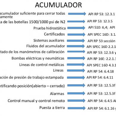
Normas Api
January 2021 2
Api 17f
February 2021 1More Documents from "rinshonsan"
Api Standard 19c
February 2021 0
Dados De Trabajo- Impresiones
January 2021 1
El Arcangel
January 2021 1
Nicholas Sparks - To Pandoxio Sti Rodanthi
February 2021 1
Rubiomorales_nancykarina_m01s4pi
February 2021 0