Cascadia Electrical System And Main Pdm Overview
This document was uploaded by user and they confirmed that they have the permission to share it. If you are author or own the copyright of this book, please report to us by using this DMCA report form. Report DMCA
Overview
Download & View Cascadia Electrical System And Main Pdm Overview as PDF for free.
More details
- Words: 43,429
- Pages: 143
Loading documents preview...
Electrical System and Main PDM Overview
G02.01 Table of Contents
System Overview Terms and Abbreviations . . . . . . . . . . . . . . . . . . . . . . . . . . . . . . . . . . . . . . . . . . . . . . . . . . . . . . . . . . . . . . Electronic Power Distribution . . . . . . . . . . . . . . . . . . . . . . . . . . . . . . . . . . . . . . . . . . . . . . . . . . . . . . . . . . . Electrical Power Distribution . . . . . . . . . . . . . . . . . . . . . . . . . . . . . . . . . . . . . . . . . . . . . . . . . . . . . . . . . . . . Main Ground Junction Block (MGJB), Module 280 . . . . . . . . . . . . . . . . . . . . . . . . . . . . . . . . . . . . . . . . . . . MEGA Fuse Junction Block (MFJB), Module 285 . . . . . . . . . . . . . . . . . . . . . . . . . . . . . . . . . . . . . . . . . . . . Powertrain PDM, Module 286 . . . . . . . . . . . . . . . . . . . . . . . . . . . . . . . . . . . . . . . . . . . . . . . . . . . . . . . . . . Load Disconnect Switch, Module 293 . . . . . . . . . . . . . . . . . . . . . . . . . . . . . . . . . . . . . . . . . . . . . . . . . . . . Trailer PDM, Module 296 . . . . . . . . . . . . . . . . . . . . . . . . . . . . . . . . . . . . . . . . . . . . . . . . . . . . . . . . . . . . . . PDM Diagram . . . . . . . . . . . . . . . . . . . . . . . . . . . . . . . . . . . . . . . . . . . . . . . . . . . . . . . . . . . . . . . . . . . . . . Related Subjects . . . . . . . . . . . . . . . . . . . . . . . . . . . . . . . . . . . . . . . . . . . . . . . . . . . . . . . . . . . . . . . . . . . .
500 501 502 503 504 505 506 507 508 509
Components Component Locations . . . . . . . . . . . . . . . . . . . . . . . . . . . . . . . . . . . . . . . . . . . . . . . . . . . . . . . . . . . . . . . . 600 Component Details . . . . . . . . . . . . . . . . . . . . . . . . . . . . . . . . . . . . . . . . . . . . . . . . . . . . . . . . . . . . . . . . . . 601 Troubleshooting Possible Causes . . . . . . . . . . . . . . . . . . . . . . . . . . . . . . . . . . . . . . . . . . . . . . . . . . . . . . . . . . . . . . . . . . . . 700 Diagnostic Tools Required . . . . . . . . . . . . . . . . . . . . . . . . . . . . . . . . . . . . . . . . . . . . . . . . . . . . . . . . . . . . . 701 Diagnosis . . . . . . . . . . . . . . . . . . . . . . . . . . . . . . . . . . . . . . . . . . . . . . . . . . . . . . . . . . . . . . . . . . . . . . . . . . 702 Specifications SAM Cab Fuses and Relays . . . . . . . . . . . . . . . . . . . . . . . . . . . . . . . . . . . . . . . . . . . . . . . . . . . . . . . . . . . SAM Chassis Fuses and Relays . . . . . . . . . . . . . . . . . . . . . . . . . . . . . . . . . . . . . . . . . . . . . . . . . . . . . . . . MFJB Fuses . . . . . . . . . . . . . . . . . . . . . . . . . . . . . . . . . . . . . . . . . . . . . . . . . . . . . . . . . . . . . . . . . . . . . . . Powertrain PDM and Trailer PDM Fuses and Relays . . . . . . . . . . . . . . . . . . . . . . . . . . . . . . . . . . . . . . . . .
Cascadia Troubleshooting Manual, August 2007
800 801 802 803
Electrical System and Main PDM Overview
G02.01
500 — Terms and Abbreviations Backbone—The main J1939 datalink wiring that lies between the two terminating resistors. It does not include the branch circuits to each ECU or to the diagnostic connector. CAN—Controller Area Network CAN ID—The identifier for a specific message, which also contains the source address of the sending ECU communicating on the J1939 datalink. CGW—Central Gateway Communication Protocol—A set of rules governing communication between electronic devices. Datalink—A collection of wires, connecting system components, through which data is transmitted. Datalink Topology—The arrangement in which the nodes (ECUs) of a datalink are connected to each other. Diagnostic CAN—Datalink that runs from the diagnostic connector to the CGW. Diagnostic Connector—A 9-pin diagnostic connector is used for troubleshooting the electrical system. MFJB—MEGA® Fuse Junction Block MGJB—Main Ground Junction Block SA—Source Address; indicates numeric assignment for a device that communicates on J1939. SAM—Signal Detect and Actuation Module SAM Cab—Signal Detect and Actuation Module Cab ("SAM Cabin"); this ECU controls mainly cab-related functionality. See G02.04 — SAM Cab for more information. SAM Chassis—Signal Detect and Actuation Module Chassis; this ECU controls mainly chassis-related functionality. See G02.05 — SAM Chassis for more information.
501 — Electronic Power Distribution The multiplexed system contains the following power distribution components: • SAM Cab (relays and fuses), Module 32A • SAM Chassis (relays and fuses), Module 32K The SAM Cab and SAM Chassis are electronic control units (ECUs) that have power distribution components such as fuses and relays on them. Refer to G02.04 — SAM Cab and G02.05 — SAM Chassis for more information.
502 — Electrical Power Distribution Standard electrical power distribution provides battery power to the electronics system, but it is not controlled by electronics. The following modules are part of power distribution: • Main Ground Junction Block (MGJB), Module 280 • MEGA Fuse Junction Block (MFJB), Module 285 • Powertrain PDM, Module 286
Cascadia Troubleshooting Manual, August 2007
G02.01/1
G02.01
Electrical System and Main PDM Overview
• Load Disconnect Switch, Module 293 • Trailer PDM, Module 296
503 — Main Ground Junction Block (MGJB), Module 280 The MGJB is a main node for connecting a returning ground to the battery. Many of the ground circuits previously on the starter are now on the MGJB.
504 — MEGA Fuse Junction Block (MFJB), Module 285 The MFJB houses up to 5 MEGA fuses, and provides power to the engine harness, SAM Cab, SAM Chassis, chassis-mounted trailer PDM, and an inverter. The advantage of using an MFJB is that it provides increased robustness in the engine control and cab control electronic systems during cranking. This is because the cab electrical system is fed from the battery through the MFJB, and no longer from the starter. Separate starter cables provide both higher voltage levels and cleaner power during cranking. Additionally, there are improvements in circuit protection, and starter connection integrity (fewer circuits to connect at the starter stud).
505 — Powertrain PDM, Module 286 The Powertrain Power Distribution Module (PT-PDM) is dedicated to providing battery and ignition power to the engine (ECM), after treatment device (ATD), transmission (TCU), as well as other powertrain-related circuits. It is mounted in the engine compartment, above the quarter fender on the driver side of the vehicle.
506 — Load Disconnect Switch, Module 293 The load disconnect switch is used to disconnect (or open) the connection between the battery and the MFJB. Turning the load disconnect switch to the off position does not disconnect the batteries from the starter.
NOTE: If the engine is running, turning the load disconnect switch to the OFF position will not shut off the engine. The powertrain PDM still gets battery voltage from the emergency power feed on the SAM system. The load disconnect switch is mounted on one of three locations: • Inside the cab on the left side of the driver’s seat on a left-hand-drive vehicle. • On the battery box. • Outboard-mounted on the left frame rail.
507 — Trailer PDM, Module 296 The trailer PDM is used to supply trailer power to the chassis-mounted trailer receptacles. The SAM Chassis supplies control outputs to the remote trailer PDM. The trailer PDM is powered through the vehicle’s battery system. The SAM Chassis does not supply battery power to the trailer PDM. See Fig. 1.
G02.01/2
Cascadia Troubleshooting Manual, August 2007
Electrical System and Main PDM Overview
G02.01
508 — PDM Diagram PT−PDM SAM Cab Emergency Power Feed
SAM Chassis Trailer PDM Inverter MFJB
MGJB
Load Disconnect Switch
04/24/2007
f545016
Fig. 1, PDM Diagram
509 — Related Subjects • G02.04 — SAM Cab • G02.05 — SAM Chassis • P01.01 — Starting and Charging
Cascadia Troubleshooting Manual, August 2007
G02.01/3
G02.01
Electrical System and Main PDM Overview
600 — Component Locations
1
7 6 5 4 3 2
f001175
06/20/2007
1. 2. 3. 4.
SAM Cab Powertrain PDM SAM Chassis Main Ground Junction Block
5. MEGA Fuse Junction Block 6. Load Disconnect Switch 7. Trailer PDM Fig. 2, Component Locations
G02.01/4
Cascadia Troubleshooting Manual, August 2007
G02.01
Electrical System and Main PDM Overview
601 — Component Details
X18 X21 X19 R11 X20
R7 F22 F1
R1
F19
R3
X4
F29
X1 X5 X14 X2 X15 X6 X3 X16 X7 X17 X8 R14 X9
F40 R15
NOTE: The square labels indicate fuses and relays, and the circular labels indicate connectors.
F13
F18
R6
F28
R10
f545092
09/19/2007
Fig. 3, SAM Cab Fuses and Relays (top)
Cascadia Troubleshooting Manual, August 2007
G02.01/5
G02.01
Electrical System and Main PDM Overview
01/25/2007
f544954
Fig. 4, SAM Chassis
6
1
2
3
4
06/20/2007
5 f545017
1. Position 1 2. Position 2 3. Position 3
4. Position 4 5. Position 5 6. Supply
Fig. 5, MEGA Fuse Junction Block
G02.01/6
Cascadia Troubleshooting Manual, August 2007
Electrical System and Main PDM Overview
05/18/2007
G02.01
f545054
Fig. 6, Powertrain PDM
700 — Possible Causes • Water Intrusion • Voltage Spikes • Short Circuits • Missing Fuse/Relay • Incorrect Fuse Rating
701 — Diagnostic Tools Required • Digital Multimeter
702 — Diagnosis Refer to the schematic in modules 280 and 285 for an overview of the vehicle power distribution system for troubleshooting. Use Table 1to cross reference the individual modules for each subsystem.
Cascadia Troubleshooting Manual, August 2007
G02.01/7
G02.01
Electrical System and Main PDM Overview
Power Distribution with Module Numbers Source
Input/Output Device
Battery Node
Module 155
Starter Bat Terminal
Starter Motor
—
Alternator Bat Terminal
Alternator
—
125
Grid Heater
Heater Element
—
12C
Jump Start Post Battery
Secondary Battery
—
Emergency Power Supply
Load Disconnect Switch
—
295
SAM Cab
—
32A
SAM Chassis
—
32K
MFJB
Powertrain PDM
286
SAM Cab
32A
SAM Chassis
32K
Trailer PDM
296
Inverter
337
Table 1, Power Distribution with Module Numbers
800 — SAM Cab Fuses and Relays SAM Cab Relays Part
Name
R1
PWR FD SPARE 1 and 3, BAT
R2
PWR FD SPARE 2 and 4, BAT
R3
HEATED SEAT, IGN
R4
DASH PWR RCPT 1 and 2, BAT
R5
FLT MGM SYS and CB, BAT
R6
PWR RCPT3 and STD HVAC, BAT
R7
DRV INFO/GAUGE, IGN
R8
ICU/VEHICLE SYS, IGN
R9
AMPLIFIER PWR, ACC
R10
MIRROR HEAT
R11
PWR RCPT 6 / FRIG, BAT
R12
PWR RCPT 5, BAT
R13
CAB LIGHTING, BAT
R14
PWR RCPT4/CIR FAN/LAMP, BAT
R15
PWR WINDOW, ACC Table 2, SAM Cab Relays
G02.01/8
Cascadia Troubleshooting Manual, August 2007
Electrical System and Main PDM Overview
G02.01
SAM Cab Fuses Part
Name
F1
PWR FD SPARE 1 and 3 (30A)
F2
CAB/SLPR HVAC CTRL/SHF PNL (15A)
F3
PWR FD SPARE 2 and 4 (30A)
F4
MSF (15A)
F5
OBD J1939—BAT (10A)
F6
DASH PWR RCPT 1 (15A)
F7
DASH PWR RCPT 2 (15A)
F8
PHONE/RADIO—BAT (15A)
F9
AMPLIFIER PWR (20A)
F10
CAB HVAC MTR (30A)
F11
SLPR HVAC MTR (30A)
F12
DR CTRL L (20A)
F13
DR LOCK/SM CRUISE (20A)
F14
FLT MGM SYS and CB (25A)
F15
SLPR PWR RCPT 3 (20A)
F16
STAND ALONE HVAC (7.5A)
F17
SLPR PWR RCPT 4 (20A)
F18
TELEMATICS/WARNING SYS (15A)
F19
HEATED SEAT (20A)
F20
CGW (2A)
F21
AREA LIGHT (15A)
F22
ICU—BAT (5A)
F23
DR INF /GAUGE (15A)
F24
ICU—IGN (10A)
F25
DASH SPLICE PACK (7.5A)
F26
SRS—AIRBAG (5A)
F27
MIRROR HEAT L (10A)
F28
MIRROR HEAT R (10A)
F29
SAM RELAY COILS (3A)
F30
PWR RCPT 6 / FRIG (20A)
F31
SLPR PWR RCPT 5 (20A)
F32
PWR FD SPARE 5 and 6 (25A)
F33
SPOT LIGHT (20A)
F34
BAGGAGE COMP LAMP (3A)
F35
DOMELAMP CAB (15A)
F36
AUX CIR FAN/RD LAMP (15A)
F37
CLK/DRV INFO/CD/KEYLESS (15A)
Cascadia Troubleshooting Manual, August 2007
G02.01/9
G02.01
Electrical System and Main PDM Overview
SAM Cab Fuses Part
Name
F38
DR CTRL R (20A)
F39
PWR WINDOW R (15A)
F40
PWR WINDOW L (15A) Table 3, SAM Cab Fuses
801 — SAM Chassis Fuses and Relays SAM Chassis Relays Part
Name
R1
H2O SEP HEAT, IGN
R2
TRLR TRN L
R3
ABS/WIF/CAMERA, IGN
R4
TRLR TRN R
R5
TRLR MARKER
R6
TRLR ABS, IGN
R7
TRLR STOP LAMPS
R8
TRLR POWER
R9
TRLR TAIL LAMPS Table 4, SAM Chassis Relays
SAM Chassis Fuses Part
G02.01/10
Name
F1
EAPU (20A)
F2
H2O SEP HEAT (20A)
R3
ABS—BAT1 (20A)
F4
ABS—BAT2 (10A)
F5
TRLR TRN L (20A)
F6
ABS—IGN (15A)
F7
WIF/CAMERA (10A)
F8
TRLR TRN R (20A)
F9
TRLR MKR (30A)
F10
SAM RELAY COILS (5A)
F11
TRLR ABS—IGN (30A)
F12
TRLR STOP (30A)
Cascadia Troubleshooting Manual, August 2007
Electrical System and Main PDM Overview
G02.01
SAM Chassis Fuses Part
Name
F13
TRLR TAIL (20A)
F14
TRLR PWR (30A) Table 5, SAM Chassis Fuses
802 — MFJB Fuses MFJB Fuses Part
Name
1
Engine Harness (175A)
2
SAM Cab (175A)
3
SAM Chassis (125A)
4
Chassis-Mounted Trailer PDM (125A)
5
Inverter (200A) Table 6, MFJB Fuses
803 — Powertrain PDM and Trailer PDM Fuses and Relays Powertrain PDM Fuses and Relays Part
Name
F1
N/A
F2
TRANS ECU IGN FUSE
F3
FUEL HEATER FUSE
F4
FUEL HEATER FUSE
F5
ENGINE IGN
F6
SAM CHASS
F7
PLVD/REMOTE SENSE
F8
ENGINE ECU BATT FUSE
F9
CPC/ENG ECU BATT FUSE
F10
TRANS BATT FUSE
F11
TRANS BATT FUSE
F12
TRANS BATT FUSE
R1
TRANS BACKUP RELAY
R2
MEIIR RELAY
R3
NEUTRAL RELAY/START ENABLE
R4
SPARE RELAY/HEAT RELAY
Cascadia Troubleshooting Manual, August 2007
G02.01/11
G02.01
Electrical System and Main PDM Overview
Powertrain PDM Fuses and Relays Part
Name
R5
N/A
R6
70A IGN RELAY
Table 7, Powertrain PDM Fuses and Relays
G02.01/12
Cascadia Troubleshooting Manual, August 2007
Datalink Communication Structure
G02.02 Table of Contents
System Overview Terms and Abbreviations . . . . . . . . . . . . . . . . . . . . . . . . . . . . . . . . . . . . . . . . . . . . . . . . . . . . . . . . . . . . . . Multiplexing Overview . . . . . . . . . . . . . . . . . . . . . . . . . . . . . . . . . . . . . . . . . . . . . . . . . . . . . . . . . . . . . . . . Vehicle Datalinks Overview . . . . . . . . . . . . . . . . . . . . . . . . . . . . . . . . . . . . . . . . . . . . . . . . . . . . . . . . . . . . SAE J1587/J1708 Datalink . . . . . . . . . . . . . . . . . . . . . . . . . . . . . . . . . . . . . . . . . . . . . . . . . . . . . . . . . . . . SAE J1939 Datalink . . . . . . . . . . . . . . . . . . . . . . . . . . . . . . . . . . . . . . . . . . . . . . . . . . . . . . . . . . . . . . . . . . Cabin CAN Datalink . . . . . . . . . . . . . . . . . . . . . . . . . . . . . . . . . . . . . . . . . . . . . . . . . . . . . . . . . . . . . . . . . . Diagnostic CAN . . . . . . . . . . . . . . . . . . . . . . . . . . . . . . . . . . . . . . . . . . . . . . . . . . . . . . . . . . . . . . . . . . . . . ECU Troubleshooting Datalinks . . . . . . . . . . . . . . . . . . . . . . . . . . . . . . . . . . . . . . . . . . . . . . . . . . . . . . . . . ECU Configuration . . . . . . . . . . . . . . . . . . . . . . . . . . . . . . . . . . . . . . . . . . . . . . . . . . . . . . . . . . . . . . . . . . . Datalink Network Topology . . . . . . . . . . . . . . . . . . . . . . . . . . . . . . . . . . . . . . . . . . . . . . . . . . . . . . . . . . . . . Related Subjects . . . . . . . . . . . . . . . . . . . . . . . . . . . . . . . . . . . . . . . . . . . . . . . . . . . . . . . . . . . . . . . . . . . .
500 501 502 503 504 505 506 507 508 509 510
Components Component Locations . . . . . . . . . . . . . . . . . . . . . . . . . . . . . . . . . . . . . . . . . . . . . . . . . . . . . . . . . . . . . . . . 600 Component Details . . . . . . . . . . . . . . . . . . . . . . . . . . . . . . . . . . . . . . . . . . . . . . . . . . . . . . . . . . . . . . . . . . 601 Troubleshooting General Troubleshooting Techniques . . . . . . . . . . . . . . . . . . . . . . . . . . . . . . . . . . . . . . . . . . . . . . . . . . . . . Diagnostic Tools Required . . . . . . . . . . . . . . . . . . . . . . . . . . . . . . . . . . . . . . . . . . . . . . . . . . . . . . . . . . . . . Fault Codes . . . . . . . . . . . . . . . . . . . . . . . . . . . . . . . . . . . . . . . . . . . . . . . . . . . . . . . . . . . . . . . . . . . . . . . . References . . . . . . . . . . . . . . . . . . . . . . . . . . . . . . . . . . . . . . . . . . . . . . . . . . . . . . . . . . . . . . . . . . . . . . . . Possible Causes . . . . . . . . . . . . . . . . . . . . . . . . . . . . . . . . . . . . . . . . . . . . . . . . . . . . . . . . . . . . . . . . . . . .
700 701 702 703 704
Specifications Wiring . . . . . . . . . . . . . . . . . . . . . . . . . . . . . . . . . . . . . . . . . . . . . . . . . . . . . . . . . . . . . . . . . . . . . . . . . . . . 800 Datalink Communication Rates . . . . . . . . . . . . . . . . . . . . . . . . . . . . . . . . . . . . . . . . . . . . . . . . . . . . . . . . . 801 ECU Identification on Datalinks . . . . . . . . . . . . . . . . . . . . . . . . . . . . . . . . . . . . . . . . . . . . . . . . . . . . . . . . . 802
Cascadia Troubleshooting Manual, August 2007
Datalink Communication Structure
G02.02
500 — Terms and Abbreviations Backbone—The main J1939 datalink wiring that lies between the two terminating resistors. It does not include the branch circuits to each ECU or to the diagnostic connector. Baud Rate—The rate at which data is transmitted in bits per second. Branch Circuit—The section of J1939 datalink between the backbone and each ECU that has J1939, and between the backbone and the diagnostic connector. Cabin CAN—A proprietary datalink connecting certain ECUs on the vehicle, specifically the CGW, MSF, SAM Cab, and SAM Chassis. CAN—Controller Area Network CAN ID—The identifier for a specific message, which also contains the source address of the sending ECU communicating on the J1939 datalink. CGW—Central Gateway Communication Protocol—A set of rules governing communication between electronic devices. Datalink—A collection of wires, connecting system components, through which data is transmitted. Datalink Topology—The arrangement in which the nodes (ECUs) of a datalink are connected to each other. Diagnostic CAN—Datalink that runs from the diagnostic connector to the CGW. Diagnostic Connector—A 9-pin diagnostic connector is used for troubleshooting the electrical system. ECU—Electronic Control Unit, typically connected to a datalink. J1939 Terminating Resistors—The J1939 datalink has two 120-ohm terminating resistors, one at each end of the backbone. The total datalink parallel resistance is 60 ohms. MID—Message Identifier MSF—Modular Switch Field Off-board tool—Typically refers to a PC-based application that communicates with the vehicle datalinks via a connection to the diagnostic connector. SA—Source Address; indicates numeric assignment for a device that communicates on J1939. SAM—Signal Detect and Actuation Module SAM Cab—Signal Detect and Actuation Module Cab ("SAM Cabin"); this ECU controls mainly cab-related functionality. See G02.04 — SAM Cab for more information. SAM Chassis—Signal Detect and Actuation Module Chassis; this ECU controls mainly chassis-related functionality. See G02.05 — SAM Chassis for more information.
501 — Multiplexing Overview The term "multiplexing" describes the electrical system. Multiplexing is defined as sending multiple electronic messages simultaneously through the same signal path. All the wires used for sending electronic messages make up what is called the "datalink." Multiplexing allows the electrical system to simultaneously perform tasks and to monitor components. A multiplexed system uses electronic control units (ECUs) to operate the various systems on the vehicle (lighting, braking, and wipers, for example). The electrical system components, such as switches and lamps, are con-
Cascadia Troubleshooting Manual, August 2007
G02.02/1
G02.02
Datalink Communication Structure
nected to the ECUs, which collect and control all information about the components by communicating on a datalink. See Fig 1.
Headlamps H
OFF
SAM Cab
P Parklamps LH Headlamp Low Beam Cab CAN
LH Headlamp High Beam SAM Chassis
RH Headlamp Low Beam
RH Headlamp High Beam
11/20/2006
f543944a
Fig. 1, Example of Multiplexed System with ECUs and Electrical Components
The multiplexed electrical system on this vehicle combines traditional power distribution module (PDM) devices, such as relays and circuit breakers, with electronic devices (ECUs) that communicate over a vehicle datalink. The electronic devices can control power distribution to the electrical loads on the vehicle. This is done by monitoring inputs (from devices such as sensors and switches) and supplying power to outputs (for devices such as lighting, displays, gauges, and indicators). This distributed approach to handling switch inputs and controlling electrical load outputs sharply reduces the number of wires on a vehicle by sharing wires.
502 — Vehicle Datalinks Overview ECUs on the Cascadia electrical system communicate on four datalinks: • J1587/J1708 datalink • J1939 datalink • Cabin CAN datalink • Diagnostic CAN datalink (used strictly for off-board tool interaction with Cabin CAN ECUs) Cabin CAN is the primary datalink for control messaging of most cab and chassis features (interior and exterior lighting, comfort features, and optional features, for example) and has some interaction with control messaging on the J1939 and J1587/J1708 datalinks.
G02.02/2
Cascadia Troubleshooting Manual, August 2007
G02.02
Datalink Communication Structure
Diagnostic CAN (500kbps)
Central Gateway
SAE J1708 (9.6kbps)
SAE J1939−13 9−Pin connector
SAM Cab
Cabin CAN (125kbps)
SAE J1939 (250kbps)
07/02/2007
f040759
Fig. 2, Central Gateway, Diagnostic Connector, and Vehicle Datalinks
J1939 and J1587/J1708 remain the primary datalinks for powertrain control (engine, transmission, and ABS, for example).
503 — SAE J1587/J1708 Datalink The J1587 datalink is a low-speed vehicle datalink that communicates information between the electronic control units on the vehicle. The J1587 datalink is also referred to as J1708 or "J1587/J1708." J1708 refers to the SAE standard for the physical part of the datalink, such as the wiring and electronic components. J1587 refers to the SAE standard for the messaging protocol that communicates on the J1708 network. In the context of vehicle repair, the terms J1708 and J1587 are used interchangeably. See G03.01 — Datalink, J1587/J1708 for more information.
504 — SAE J1939 Datalink The J1939 datalink is a high-speed vehicle datalink that communicates information between electronic control units on the vehicle. Unlike the J1587 datalink, the J1939 datalink allows an ECU to broadcast requests as well as information. Examples of information that can be communicated on the J1939 datalink are: • engine rotational speed; • road speed; • transmission tailshaft speed; • engine retarder deactivation request; • engine torque reduction request. The "backbone" of the J1939 datalink is the section of the datalink that is between the two terminating resistors. Each ECU is connected to the backbone. The wiring between each ECU and the backbone is referred to as a branch. See G03.02 — Datalink, J1939 for more details.
Cascadia Troubleshooting Manual, August 2007
G02.02/3
G02.02
Datalink Communication Structure
505 — Cabin CAN Datalink The Cabin CAN datalink does not have a direct connection to the diagnostic connector. Therefore, an off-board tool (such as ServiceLink) must connect to the Diagnostic CAN pins on the diagnostic connector to troubleshoot or configure Cabin CAN ECUs. The Cabin CAN datalink has the following ECUs directly connected to it: • SAM Cab • SAM Chassis • Modular Switch Field (MSF) • Central Gateway Module (CGW) See G03.03 — Datalink, Cabin CAN for more information.
506 — Diagnostic CAN When an off-board tool, such as ServiceLink, is connected to the vehicle, it communicates with the Cabin CAN ECUs via the Diagnostics CAN datalink because there is no accessible service port to the Cabin CAN. The CGW translates messages between the Diagnostic CAN and Cabin CAN datalinks, due to the different speed of the two datalinks. See G03.04 — Datalink, Diagnostic CAN for more information.
507 — ECU Troubleshooting Datalinks An ECU’s "troubleshooting datalink" is the datalink that an off-board tool, such as ServiceLink, uses to communicate and diagnose that ECU. See Table 1. ECU Troubleshooting Datalinks ECU is on this Datalink
Direct Connection to Diagnostic Connector?
ECU Troubleshooting Datalink
Direct Connection to Diagnostic Connector?
Diagnostic Communication Protocol
J1708
Yes
J1587/J1708
Yes
J1587/J1708
J1939
Yes
J1939
Yes
J1939
Cabin CAN
No
Diagnostic CAN
Yes
CAN
Table 1, ECU Troubleshooting Datalinks
Fault codes are displayed on the instrument cluster (ICU) display for J1587/J1708 or J1939, depending on the type of ICU installed. Faults from all ECUs can be viewed on ServiceLink.
508 — ECU Configuration All ECUs connected to the Cabin CAN datalink can have their software “flashed” using ServiceLink. All ECUs connected to the Cabin CAN datalink, except for the CGW, have parameters that can be configured. Some J1939 and J1587/J1708 ECUs may be reprogrammed (flashed), or have parameters configured, using ServiceLink or the ECU manufacturer’s proprietary off-board tool. For more information, refer to the applicable
G02.02/4
Cascadia Troubleshooting Manual, August 2007
G02.02
Datalink Communication Structure
subjects in this manual, and the ServiceLink User Documentation (available via the "Help" drop-down menu in ServiceLink).
509 — Datalink Network Topology Cascadia Network Topology Diagnostic CAN (500kbps)
Central Gateway
SAE J1708 (9.6kbps)
SAE J1939−13 9−Pin connector
SAM Cab
Cabin CAN (125kbps)
SAE J1939 (250kbps)
Engine Control Module
SAM Chassis Pneumatic ABS Module
Modular Switch Field (Master)
Transmission Control Module
Sub Bus Slave Switch Control Panels
Steering Wheel Switches
Head Lamp Switch
Stalk Switch (Steering Column)
Instrument Cluster
HVAC Control Switches Front
HVAC Control Switches Rear
Standard Radio
Optional
VORAD
Engine Display
Qualcomm
07/02/2007
f040753
Fig. 3, Datalink Network Topology
Cascadia Troubleshooting Manual, August 2007
G02.02/5
G02.02
Datalink Communication Structure
510 — Related Subjects • G02.01 — Electrical System and Main PDM Overview • G02.03 — Central Gateway • G02.04 — SAM Cab • G02.05 — SAM Chassis • G02.06 — Modular Switch Field • G03.01 — Datalink, J1587/J1708 • G03.02 — Datalink, J1939 • G03.03 — Datalink, Cabin CAN • G03.04 — Datalink, Diagnostic CAN
G02.02/6
Cascadia Troubleshooting Manual, August 2007
G02.02
Datalink Communication Structure
600 — Component Locations
3
2
4
1
5
6
05/08/2007
1. 2. 3. 4.
SAM Cab Starpoint Connector Central Gateway Modular Switch Field
7
f544899
5. J1939 Terminating Resistor 6. Diagnostic Connector 7. SAM Chassis Fig. 4, Component Locations
Cascadia Troubleshooting Manual, August 2007
G02.02/7
G02.02
Datalink Communication Structure
601 — Component Details
D E
C A
F
B J
G H 05/01/2006
f151036b
Fig. 5, Diagnostic Connector Diagnostic Connector Pin
Function
A
Battery (–)
B
Battery (+)
C
J1939 CAN High (+)
D
J1939 CAN Low (–)
E
CAN Shield (ground)
F
J1708/J1587 (+)
G
J1708/J1587 (–)
H
Diagnostic CAN High (+)
J
Diagnostic CAN Low (–) Table 2, Diagnostic Connector
08/29/2008
f544911
Fig. 6, Central Gateway Module, Cabin CAN Pins
G02.02/8
Cascadia Troubleshooting Manual, August 2007
Datalink Communication Structure
G02.02
CGW ECU (single connector) Pin
Function
1
Battery Power
2
J1708 (+)
3
Not used
4
Not used
5
Not used
6
Not used
7
Ground
8
J1708 (–)
9
Not used
10
Not used
11
Not used
12
Not used
13
Not used
14
Cabin CAN Low
15
Not used
16
J1939 CAN Low
17
Not used
18
Diagnostic CAN Low
19
Cabin CAN High
20
Not used
21
J1939 CAN High
22
Not used
23
Diagnostic CAN High
24
Not used Table 3, CGW ECU (single connector)
Cascadia Troubleshooting Manual, August 2007
G02.02/9
G02.02
Datalink Communication Structure
1
4
7
10
13
16
2
5
8
11
14
17
3
6
9
12
15
18
12/04/2006
f544912
Fig. 7, Starpoint Connector CGW ECU (single connector) Pin
Function
1
Cabin CAN High (to CGW)
2
Not connected
3
Cabin CAN Low (to CGW)
4
Cabin CAN High (to SAM Cab)
5
Not connected
6
Cabin CAN Low (to SAM Cab)
7
Cabin CAN High (to SAM Chassis)
8
Not connected
9
Cabin CAN Low (to SAM Chassis)
10
Cabin CAN High (to MSF)
11
Not connected
12
Cabin CAN Low (to MSF)
13
Not connected
14
Not connected
15
Not connected
16
Not connected
17
Ground
18
Not connected Table 4, CGW ECU (single connector)
G02.02/10
Cascadia Troubleshooting Manual, August 2007
G02.02
Datalink Communication Structure
f610854
11/29/2006
Fig. 8, Central Gateway
2
04/26/2006
1
f544831
1. Connector Tee 2. Terminating Resistor Fig. 9, Connector Tee
Cascadia Troubleshooting Manual, August 2007
G02.02/11
G02.02
Datalink Communication Structure
1
04/18/2006
f544832
1. Terminating Resistor Fig. 10, Terminating Resistor
700 — General Troubleshooting Techniques Follow the steps below to troubleshoot the datalinks. 1.
Identify which datalink has a problem.
2.
Perform general electrical troubleshooting for wiring continuity and connections.
3.
Refer to individual datalink chapters for more info to troubleshoot the specific datalink.
701 — Diagnostic Tools Required • ServiceLink
702 — Fault Codes Refer to G03.01 — Datalink, J1587/J1708 to troubleshoot the J1587 and J1708 datalink. Refer to G03.02 — Datalink, J1939 to troubleshoot the J1939 datalink. Refer to G03.03 — Datalink, Cabin CAN to troubleshoot the Cabin CAN datalink. Refer to G03.04 — Datalink, Diagnostic CAN to troubleshoot the Diagnostic CAN datalink.
703 — References Refer to G01.04 — How to Locate a Schematic for information on wiring.
704 — Possible Causes Any Datalink: • wiring • any ECU connected to the problem datalink J1939 Datalink: • terminal resistor value on J1939 datalink Cabin CAN Datalink: • starpoint connector resistor value on Cabin CAN datalink
G02.02/12
Cascadia Troubleshooting Manual, August 2007
G02.02
Datalink Communication Structure
800 — Wiring Wiring Wire Color
Datalink
High
Low
Yellow
Dark Green
Dark Green
Orange
Cabin CAN
Light Blue
White
Diagnostic CAN
Brown with Light Blue Stripe
Brown with White Stripe
J1939 J1587/J1708
Table 5, Wiring
801 — Datalink Communication Rates Datalink Communication Rates Datalink
Kilobits Per Second
J1939
250
J1587/J1708
9600
Cabin CAN
125
Diagnostic CAN
500
Table 6, Datalink Communication Rates
802 — ECU Identification on Datalinks ECU Identification on Datalinks ECU Description
J1587 MID*
J1939 SA†
CAN ID
Engine
128
0
—
Transmission
130
3
—
Antilock Brakes
136
11
—
Instrument Cluster
140
23
—
Vehicle Security Unit (VSU)
163
—
—
Data Logging Unit (DLU)
179
251
—
Collision Avoidance System (headway controller)
219
42
—
SAM Cab
—
—
33
SAM Chassis
—
—
71
Cascadia Troubleshooting Manual, August 2007
G02.02/13
G02.02
Datalink Communication Structure
ECU Identification on Datalinks ECU Description
J1587 MID*
J1939 SA†
CAN ID
Modular Switch Field
—
—
49
Central Gateway
—
—
37
* Message Identifier † Source Address
Table 7, ECU Identification on Datalinks
G02.02/14
Cascadia Troubleshooting Manual, August 2007
Central Gateway
G02.03 Table of Contents
System Overview Terms and Abbreviations . . . . . . . . . . . . . . . . . . . . . . . . . . . . . . . . . . . . . . . . . . . . . . . . . . . . . . . . . . . . . . General Information . . . . . . . . . . . . . . . . . . . . . . . . . . . . . . . . . . . . . . . . . . . . . . . . . . . . . . . . . . . . . . . . . . Routing and Translating Messages Between Datalinks . . . . . . . . . . . . . . . . . . . . . . . . . . . . . . . . . . . . . . . Interface Between Off-Board Tools and Cabin CAN ECUs . . . . . . . . . . . . . . . . . . . . . . . . . . . . . . . . . . . . . ECU Monitoring . . . . . . . . . . . . . . . . . . . . . . . . . . . . . . . . . . . . . . . . . . . . . . . . . . . . . . . . . . . . . . . . . . . . . ECU Configuration . . . . . . . . . . . . . . . . . . . . . . . . . . . . . . . . . . . . . . . . . . . . . . . . . . . . . . . . . . . . . . . . . . . Related Subjects . . . . . . . . . . . . . . . . . . . . . . . . . . . . . . . . . . . . . . . . . . . . . . . . . . . . . . . . . . . . . . . . . . . . Datalink Network Topology . . . . . . . . . . . . . . . . . . . . . . . . . . . . . . . . . . . . . . . . . . . . . . . . . . . . . . . . . . . . .
500 501 502 503 504 505 506 507
Components Component Locations . . . . . . . . . . . . . . . . . . . . . . . . . . . . . . . . . . . . . . . . . . . . . . . . . . . . . . . . . . . . . . . . 600 Component Details . . . . . . . . . . . . . . . . . . . . . . . . . . . . . . . . . . . . . . . . . . . . . . . . . . . . . . . . . . . . . . . . . . 601 Troubleshooting Required Tools . . . . . . . . . . . . . . . . . . . . . . . . . . . . . . . . . . . . . . . . . . . . . . . . . . . . . . . . . . . . . . . . . . . . . . 700 Possible Causes . . . . . . . . . . . . . . . . . . . . . . . . . . . . . . . . . . . . . . . . . . . . . . . . . . . . . . . . . . . . . . . . . . . . 701 Fault Codes . . . . . . . . . . . . . . . . . . . . . . . . . . . . . . . . . . . . . . . . . . . . . . . . . . . . . . . . . . . . . . . . . . . . . . . . 702
Cascadia Troubleshooting Manual, November 2007
Central Gateway
G02.03
500 — Terms and Abbreviations Baud Rate—The rate at which data is transmitted in bits per second. CAN—Controller Area Network CGW—Central Gateway Communication Protocol—A set of rules governing communication between electronic devices. Datalink—A collection of wires, connecting system components, through which data is transmitted. Diagnostic CAN—Datalink that runs from the diagnostic connector to the CGW. ECU—Electronic Control Unit, typically connected to a datalink. MSF—Modular Switch Field Off-board tool—Typically refers to a PC-based application that communicates with the vehicle datalinks via a connection to the diagnostic connector. Parameter—A parameter is a specific value that is assigned to a feature or function of the vehicle, and allows the customer to choose how that particular feature or function will work on the vehicle. SA—Source Address; indicates numeric assignment for a device that communicates on J1939. SAE—Society of Automotive Engineers SAM—Signal Detect and Actuation Module SAM Cab—Signal Detect and Actuation Module Cab ("SAM Cabin"); this ECU controls mainly cab-related functionality. See G02.04 — SAM Cab for more information. SAM Chassis—Signal Detect and Actuation Module Chassis; this ECU controls mainly chassis-related functionality. See G02.05 — SAM Chassis for more information.
501 — General Information The Central Gateway is an ECU (Electronic Control Unit), also called the "Central Gateway" (CGW) ECU. The CGW has the following wiring connections: • Each datalink on the vehicle: J1708, J1939, Cabin CAN, and Diagnostic CAN. • On the Diagnostic CAN, the CGW has a direct connection to the diagnostic connector. • On the Cabin CAN, the CGW is directly connected to the starpoint connector.
Cascadia Troubleshooting Manual, November 2007
G02.03/1
G02.03
Central Gateway
Diagnostic CAN (500kbps)
Central Gateway
SAE J1708 (9.6kbps)
SAE J1939−13 9−Pin connector
SAM Cab
Cabin CAN (125kbps)
SAE J1939 (250kbps)
07/02/2007
f040759
Fig. 1, Central Gateway, Diagnostic Connector, and Vehicle Datalinks
The CGW has the following main functions: • Routes and translates messages between datalinks. • Interfaces between off-board tools and Cabin CAN ECUs. • Provides faults for any missing Cabin CAN ECUs. The CGW receives battery power and ground from the SAM Cab; power comes through a 2A fuse (F20) on the SAM Cab.
502 — Routing and Translating Messages Between Datalinks The primary function of the CGW is to connect the four datalinks on the vehicle, and to route and translate the datalink messages between them. The J1939, J1708, Cabin CAN, and Diagnostic CAN datalinks have different characteristics, but they all work together to control the vehicle. The CGW acts as a translator between the communication protocols used on the various datalinks. In some instances, the Cabin CAN ECUs need information from J1939 or J1708 ECUs. In these cases, information is sent by the J1939 or J1708 ECU. The CGW picks up the information and passes it to the appropriate Cabin CAN ECU. Similarly, the reverse happens when a J1939 or J1708 ECU needs information from a Cabin CAN ECU. An example of Cabin CAN and J1939 interaction is the optional cruise control feature. The Engine ECU on the J1939 datalink broadcasts a message containing vehicle speed. The SAM Cab ECU on the Cabin CAN datalink uses the vehicle speed information to perform the cruise control feature. The vehicle speed message flows from the engine ECU to the SAM Cab as follows: 1.
The engine ECU broadcasts the vehicle speed message on J1939.
2.
The vehicle speed message is picked up by the CGW, from J1939 datalink.
3.
The central gateway translates the vehicle speed message from J1939’s communication protocol to the Cabin CAN communication protocol.
4.
The central gateway routes the vehicle speed message to the Cabin CAN datalink.
5.
The vehicle speed message is received by the SAM Cab ECU, and the information is used for cruise control logic.
G02.03/2
Cascadia Troubleshooting Manual, November 2007
Central Gateway
G02.03
503 — Interface Between Off-Board Tools and Cabin CAN ECUs The CGW acts as the interface between ECUs on the Cabin CAN and the outside world. Unlike the J1708 and J1939 datalink, the Cabin CAN datalink does not have its own direct connection to the diagnostic connector. Instead, it is connected to the CGW, which in turn has a direct connection to the diagnostic connector via the Diagnostic CAN datalink. The CGW separates the Cabin CAN from off-board tools and acts as a firewall, which protects Freightliner’s proprietary Cabin CAN datalink from "public" access. This allows for better protection from electrical damage and better control of electrical capabilities, which leads to higher reliability for the ECUs.
504 — ECU Monitoring The CGW monitors for any missing Cabin CAN ECUs. Each missing Cabin CAN ECU is described in a CAN fault code generated by the CGW. The CGW monitors all messages on the Cabin CAN datalink to see if an ECU stops sending messages. If this happens, the CGW will report a fault code that a particular ECU is missing. The possible fault codes for missing ECUs are listed in 702 — Fault Codes. The ECU monitoring function stops when: • under or over voltage is detected; • the Cabin CAN stops communicating.
505 — ECU Configuration The diagnostic protocol used for troubleshooting or configuring the Central Gateway is the Controller Area Network (CAN). The Central Gateway does not have any parameters to configure. The Central Gateway can be flashed using ServiceLink, which will flash to its same version or upgrade, if required. The software flashing procedure should only be performed on the CGW in the following cases: • Feature upgrade: Adding a new feature to a vehicle may require a newer version of ECU software. ServiceLink will automatically make available any necessary software upgrades. • Fixing a software problem in the existing software: In case a new version of ECU software is needed to fix a problem in the existing ECU software, ServiceLink will automatically make available any necessary software upgrades. • Replacement of the Central Gateway: Flashing ensures that the most recent software is on the installed ECU. • As a last resort: Troubleshooting has narrowed the problem down to being at the Central Gateway itself and no other mechanical or electrical causes for the symptom have been identified. As a last resort before swapping the ECU, flashing the CGW software with the same version may help in the case it became corrupt during the course of normal vehicle operation. For instructions on how to use ServiceLink to flash the software of a CAN ECU like the Central Gateway, refer to the ServiceLink User Guide or ServiceLink Help user documentation, available in ServiceLink’s "Help" menu.
Cascadia Troubleshooting Manual, November 2007
G02.03/3
G02.03
Central Gateway
506 — Related Subjects • G02.02 — Datalink Communication Structure • G02.04 — SAM Cab • G02.05 — SAM Chassis • G02.06 — Modular Switch Field • G03.01 — Datalink, J1587/J1708 • G03.02 — Datalink, J1939 • G03.03 — Datalink, Cabin CAN • G03.04 — Datalink, Diagnostic CAN
G02.03/4
Cascadia Troubleshooting Manual, November 2007
G02.03
Central Gateway
507 — Datalink Network Topology Cascadia Network Topology Diagnostic CAN (500kbps)
Central Gateway
SAE J1708 (9.6kbps)
SAE J1939−13 9−Pin connector
SAM Cab
Cabin CAN (125kbps)
SAE J1939 (250kbps)
Engine Control Module
SAM Chassis Pneumatic ABS Module
Modular Switch Field (Master)
Transmission Control Module
Sub Bus Slave Switch Control Panels
Steering Wheel Switches
Head Lamp Switch
Stalk Switch (Steering Column)
Instrument Cluster
HVAC Control Switches Front
HVAC Control Switches Rear
Standard Radio
Optional
VORAD
Engine Display
Qualcomm
f040753
07/02/2007
Fig. 2, Datalink Network Topology
Cascadia Troubleshooting Manual, November 2007
G02.03/5
G02.03
Central Gateway
600 — Component Locations
2
1
D E
C A
F
B J
G H
3 11/27/2006
1. Starpoint Connector
f544909
2. Central Gateway
3. Diagnostic Connector
Fig. 3, Component Locations
G02.03/6
Cascadia Troubleshooting Manual, November 2007
G02.03
Central Gateway
601 — Component Details
D E
C A
F
B J
G H 05/01/2006
f151036b
Fig. 4, Diagnostic Connector Diagnostic Connector Pin
Function
A
Battery (–)
B
Battery (+)
C
J1939 CAN High (+)
D
J1939 CAN Low (–)
E
Reserved
F
J1708/J1587 (+)
G
J1708/J1587 (–)
H
Diagnostic CAN High (+)
J
Diagnostic CAN Low (–) Table 1, Diagnostic Connector
07/02/2007
24
18
12
19
13
7
6
1 f544911
Fig. 5, Central Gateway Module, Cabin CAN Pins
Cascadia Troubleshooting Manual, November 2007
G02.03/7
G02.03
Central Gateway
CGW ECU (single connector) Pin
Function
1
Battery Power
2
J1708/J1587 (+)
7
Ground
8
J1708/J1587 (–)
14
Cabin CAN Low (–)
16
J1939 Low (–)
18
Diagnostic CAN Low (–)
19
Cabin CAN High (+)
21
J1939 High (+)
23
Diagnostic CAN High (+) Table 2, CGW ECU (single connector)
f610854
11/29/2006
Fig. 6, Central Gateway
700 — Required Tools • ServiceLink
701 — Possible Causes • Fuse F20 (CGW power) on the SAM Cab • Wiring
G02.03/8
Cascadia Troubleshooting Manual, November 2007
G02.03
Central Gateway
• Starpoint Connector (Cabin CAN) • CGW • J1939 Terminating Resistors • J1587/J1708 Junction Block • Diagnostic Connector • Cabin CAN ECUs
702 — Fault Codes Fault Codes SA
SPN
FMI
Fault Description
Fault Trigger
37
168
4
Battery Power—Voltage below normal or shorted to low
CGW battery power (pin 1) fell below the lower limit of the system voltage range: 9V.
37
168
3
Battery Power—Voltage above normal or shorted to high
CGW battery power (pin 1) exceeded the upper limit of the system voltage range: 16V.
37
628
12
Program Memory—Bad intelligent device or component
The memory in the CGW has a problem. Cabin CAN perfomance failures (communication is not possible) occur when:
37
523510
31
Diagnostic CAN Performance
• Diagnostic CAN High is shorted to GND • Diagnostic CAN Low is shorted to BAT • Diagnostic CAN Low is shorted to Diagnostic CAN High Cabin CAN perfomance failures (communication is not possible) occur when:
37
523511
31
Cabin CAN Performance
• Cabin CAN High is shorted to GND • Cabin CAN Low is shorted to BAT • Cabin CAN Low is shorted to Cabin CAN High J1939 CAN performance failures (communication is not possible) occur when:
37
523512
31
J1939 CAN Performance
• J1939 CAN High is shorted to GND • J1939 CAN Low is shorted to BAT • J1939 CAN Low is shorted to J1939 CAN High J1708 performance errors occur when:
• The busload (i.e. amount of data traffic) on 37
523513
31
J1708 Performance
J1708 is too high.
• The CAN datalinks (Cabin CAN, Diagnostic CAN, J1939 CAN) have extremely high busload.*
Cascadia Troubleshooting Manual, November 2007
G02.03/9
G02.03
Central Gateway
Fault Codes SA
37
37
37
SPN
524033
524049
524071
FMI
31
31
31
Fault Description
Fault Trigger
Lost communication with SAM_CAB
Trigger: The fault is triggered when the CGW does not see any messages from the SAM Cab for at least 20 seconds. The fault becomes historic as soon as the CGW sees messages from the SAM Cab. Vehicle Behavior: The SAM Cab and SAM Chassis outputs may be behaving according to "Emergency Power Mode" for a SAM Cab failure. An indication of a SAM Cab failure is that all gauges in the instrumentation control unit (ICU) drop to zero because power to the ICU is lost. Possible Causes: The SAM Cab is not connected to the Cabin CAN datalink, or does not have power. Action: Check wiring from the Cabin CAN to the SAM Cab, and the CGW. Check the SAM Cab power supply cables.
Lost communication with MSF
Trigger: The fault is triggered when the CGW does not see any messages from the MSF for at least 20 seconds. The fault becomes historic as soon as the CGW sees messages from the MSF. Vehicle Behavior: Headlights automatically turn on for safety. All functions where input switches are controlled by the MSF do not function, such as turn and hazard functions, rotary switch (headlamp) functions, and wiper. Action: Check Cabin CAN wiring, especially connections to the MSF and the CGW. Check MSF power supply.
Lost communication with SAM_CHAS
Trigger: The fault is triggered when the CGW does not see any messages from the SAM Chassis for at least 20 seconds. The fault becomes historic as soon as the CGW sees messages from the SAM Chassis. Vehicle Behavior: SAM Cab and SAM Chassis outputs may be behaving according to "Emergency Power Mode" for a SAM Chassis failure. An indication of a SAM Chassis failure is that the ICU turn signal indicators flash alternately. Possible Causes: The SAM Chassis is not connected to the Cabin CAN datalink, or does not have power. Action: Check wiring from the Cabin CAN to the SAM Chassis, and the CGW. Check the SAM Chassis power supply cables.
* High bus load on a datalink may be caused by a faulty ECU, which broadcasts erroneous data, clogging up communication on the datalink.
Table 3, Fault Codes
G02.03/10
Cascadia Troubleshooting Manual, November 2007
SAM Cab
G02.04 Table of Contents
System Overview Terms and Abbreviations . . . . . . . . . . . . . . . . . . . . . . . . . . . . . . . . . . . . . . . . . . . . . . . . . . . . . . . . . . . . . . General Information . . . . . . . . . . . . . . . . . . . . . . . . . . . . . . . . . . . . . . . . . . . . . . . . . . . . . . . . . . . . . . . . . . Fuses and Relays . . . . . . . . . . . . . . . . . . . . . . . . . . . . . . . . . . . . . . . . . . . . . . . . . . . . . . . . . . . . . . . . . . . Datalink Connections . . . . . . . . . . . . . . . . . . . . . . . . . . . . . . . . . . . . . . . . . . . . . . . . . . . . . . . . . . . . . . . . . Diagnostic CAN Datalink . . . . . . . . . . . . . . . . . . . . . . . . . . . . . . . . . . . . . . . . . . . . . . . . . . . . . . . . . . . . . . Functional Messaging and ECU Troubleshooting . . . . . . . . . . . . . . . . . . . . . . . . . . . . . . . . . . . . . . . . . . . . ECU Configuration . . . . . . . . . . . . . . . . . . . . . . . . . . . . . . . . . . . . . . . . . . . . . . . . . . . . . . . . . . . . . . . . . . . Datalink Network Topology . . . . . . . . . . . . . . . . . . . . . . . . . . . . . . . . . . . . . . . . . . . . . . . . . . . . . . . . . . . . .
500 501 502 503 504 505 506 507
Components Component Locations . . . . . . . . . . . . . . . . . . . . . . . . . . . . . . . . . . . . . . . . . . . . . . . . . . . . . . . . . . . . . . . . Component Details . . . . . . . . . . . . . . . . . . . . . . . . . . . . . . . . . . . . . . . . . . . . . . . . . . . . . . . . . . . . . . . . . . Pinout Mapping . . . . . . . . . . . . . . . . . . . . . . . . . . . . . . . . . . . . . . . . . . . . . . . . . . . . . . . . . . . . . . . . . . . . . Fuse Mapping . . . . . . . . . . . . . . . . . . . . . . . . . . . . . . . . . . . . . . . . . . . . . . . . . . . . . . . . . . . . . . . . . . . . . . Relay Mapping . . . . . . . . . . . . . . . . . . . . . . . . . . . . . . . . . . . . . . . . . . . . . . . . . . . . . . . . . . . . . . . . . . . . . .
600 601 602 603 604
Troubleshooting Troubleshooting Overview . . . . . . . . . . . . . . . . . . . . . . . . . . . . . . . . . . . . . . . . . . . . . . . . . . . . . . . . . . . . . Required Tools . . . . . . . . . . . . . . . . . . . . . . . . . . . . . . . . . . . . . . . . . . . . . . . . . . . . . . . . . . . . . . . . . . . . . . Possible Causes . . . . . . . . . . . . . . . . . . . . . . . . . . . . . . . . . . . . . . . . . . . . . . . . . . . . . . . . . . . . . . . . . . . . Fault Codes . . . . . . . . . . . . . . . . . . . . . . . . . . . . . . . . . . . . . . . . . . . . . . . . . . . . . . . . . . . . . . . . . . . . . . . . Grounded Pins and Inputs . . . . . . . . . . . . . . . . . . . . . . . . . . . . . . . . . . . . . . . . . . . . . . . . . . . . . . . . . . . . . Fused and FET Controlled Outputs . . . . . . . . . . . . . . . . . . . . . . . . . . . . . . . . . . . . . . . . . . . . . . . . . . . . . . Relayed Outputs . . . . . . . . . . . . . . . . . . . . . . . . . . . . . . . . . . . . . . . . . . . . . . . . . . . . . . . . . . . . . . . . . . . . Logic Controlled Unfused Outputs . . . . . . . . . . . . . . . . . . . . . . . . . . . . . . . . . . . . . . . . . . . . . . . . . . . . . . . Logic Controlled Relayed Fused Outputs . . . . . . . . . . . . . . . . . . . . . . . . . . . . . . . . . . . . . . . . . . . . . . . . . . Unfused Constant Outputs . . . . . . . . . . . . . . . . . . . . . . . . . . . . . . . . . . . . . . . . . . . . . . . . . . . . . . . . . . . . . Fused Battery Pass-Through Outputs . . . . . . . . . . . . . . . . . . . . . . . . . . . . . . . . . . . . . . . . . . . . . . . . . . . .
700 701 702 703 704 705 706 707 708 709 710
Specifications Maximum Current Pin List . . . . . . . . . . . . . . . . . . . . . . . . . . . . . . . . . . . . . . . . . . . . . . . . . . . . . . . . . . . . . 800
Cascadia Troubleshooting Manual, March 2010
SAM Cab
G02.04
500 — Terms and Abbreviations Baud Rate—The rate at which data is transmitted in bits per second. Cabin CAN—A proprietary datalink connecting certain ECUs on the vehicle, specifically the CGW, MSF, SAM Cab, and SAM Chassis. CAN—Controller Area Network CAN ID—The identifier for a specific message, which also contains the source address of the sending ECU communicating on the J1939 datalink. CGW—Central Gateway CPC—Common Powertrain Controller (for M-B and DDC engines only). Communication Protocol—A set of rules governing communication between electronic devices. Datalink—A collection of wires, connecting system components, through which data is transmitted. Datalink Topology—The arrangement in which the nodes (ECUs) of a datalink are connected to each other. Diagnostic CAN—Datalink that runs from the diagnostic connector to the CGW. Diagnostic Connector—A 9-pin diagnostic connector is used for troubleshooting the electrical system. FMI—Failure Mode Indicator. The part of a J1587, J1939, and CAN fault code that identifies how part of a device, or item on a device, failed. HVAC—Heating, Ventilation, and Air Conditioning ICU—Instrumentation Control Unit I/O Controls—Input/Output controls allow a technician to activate and deactivate an input or output pin for troubleshooting purposes. I/O controls appear on ServiceLink templates as buttons, typically labeled "ON" and "OFF." ISS—Ignition Switch Status MSF—Modular Switch Field NO—Normally Open NC—Normally Closed Off-board tool—Typically refers to a PC-based application that communicates with the vehicle datalinks via a connection to the diagnostic connector. OBD—Onboard Diagnostics Parameter—A parameter is a specific value that is assigned to a feature or function of the vehicle, and allows the customer to choose how that particular feature or function will work on the vehicle. PDM—Power Distribution Module PLVD—Progressive Low Voltage Disconnect SA—Source Address; indicates numeric assignment for a device that communicates on J1939. SAM Cab—Signal Detect and Actuation Module Cab ("SAM Cabin"); this ECU controls mainly cab-related functionality.
Cascadia Troubleshooting Manual, March 2010
G02.04/1
G02.04
SAM Cab
SAM Chassis—Signal Detect and Actuation Module Chassis; this ECU controls mainly chassis-related functionality. See G02.05 — SAM Chassis for more information. SPN—Suspect Parameter Number. The part of a J1939 or CAN fault code that identifies how part of a device, or item on a device, failed.
501 — General Information The SAM Cab is an ECU (Electronic Control Unit). It is also referred to as the "SAM Cabin." The SAM Cab works closely with the SAM Chassis to control much of the vehicle functionality. The SAM Cab controls most of the cab functions. The SAM Chassis controls most of the chassis functions. This ECU uses inputs (such as switches, sensors, and datalink messages) and drives outputs (such as lights, motors, and solenoids). See 601 — Component Details for complete pin information.
IMPORTANT: This subject describes the SAM Cab ECU in general terms. To understand a particular function or system that the SAM Cab is part of, see the appropriate subject in this manual on that function or system. Each subject contains details about the way a function should work, as well as crucial information such as inputs, outputs, interlocks, any related parameters for that particular function, and any other ECUs or components that are a part of that function.
502 — Fuses and Relays The SAM Cab houses a number of fuses and relays. See 601 — Component Details for fuse and relay locations. See 602 — Pinout Mapping, 603 — Fuse Mapping, and 604 — Relay Mapping for the functions associated with each pin, fuse, and relay. For more information on the power distribution system, see G02.01 — Electrical System and Main PDM Overview.
503 — Datalink Connections The SAM Cab is connected directly to the Cabin CAN datalink. Cabin CAN wires run from the SAM Cab to the starpoint connector, where it joins the rest of the Cabin CAN datalink. See G03.03 — Datalink, Cabin CAN for details.
504 — Diagnostic CAN Datalink When an off-board tool, such as ServiceLink, is connected to the vehicle, it communicates with the Cabin CAN ECUs via the Diagnostics CAN datalink; there is no accessible service port to the Cabin CAN. The CGW translates between the Diagnostics CAN and Cabin CAN datalink, due to the different speed and message formats of the two datalinks.
505 — Functional Messaging and ECU Troubleshooting To communicate with the ECU, a different set of messages is used by the off-board tool during troubleshooting than the set of messages used during normal operation. The set of messages used during normal operation is referred to as functional messages, which are sent cyclically on the Cabin CAN datalink. However, the set of messages (protocol) used during troubleshooting is referred to as Control Area Network (CAN), which operates on a request-and-response basis over the Diagnostic CAN datalink.
G02.04/2
Cascadia Troubleshooting Manual, March 2010
SAM Cab
G02.04
Any fault reported on the Cabin CAN is translated to Diagnostics CAN by the CGW, and can be displayed when requested by an off-board tool, such as ServiceLink. Similarly, an off-board tool is able to display input and output pin status information, software interlocks, and allows a user to control inputs or outputs for troubleshooting. This information is displayed in ServiceLink’s Datalink Monitor (DLM) templates.
506 — ECU Configuration The diagnostic protocol used for troubleshooting or configuring the SAM Cab is the Control Area Network (CAN). For more information on CAN, see G03.04 — Datalink, Diagnostic CAN. The SAM Cab has parameters that can be viewed or changed for vehicle configuration. The SAM Cab software can be flashed using ServiceLink, which will flash to its same version or upgrade, if required. The software flashing procedure should only be performed on the SAM Cab in the following cases: • As a last resort: Troubleshooting has narrowed the problem down to being at the SAM Cab itself and no other mechanical or electrical causes for the symptom have been identified. As a last resort, flashing the SAM Cab software with the same version may help in the case it became corrupt during the course of normal vehicle operation. • For a feature upgrade: Adding a new feature to a vehicle may require a newer version of ECU software. ServiceLink will automatically make available any necessary software upgrades. • Fixing a problem in the existing software: In case a new version of ECU software is needed to fix a problem in the existing ECU software, ServiceLink will automatically make available any necessary software upgrades. • Replacing the SAM Cab: Flashing ensures that the most recent software is on the installed ECU. For instructions on how to use ServiceLink to flash the software of a CAN ECU like the SAM Cab, refer to the ServiceLink User Guide or ServiceLink Help user documentation, available in ServiceLink’s "Help" menu.
Cascadia Troubleshooting Manual, March 2010
G02.04/3
G02.04
SAM Cab
507 — Datalink Network Topology Cascadia Network Topology Diagnostic CAN (500kbps)
Central Gateway
SAE J1708 (9.6kbps)
SAE J1939−13 9−Pin connector
SAM Cab
Cabin CAN (125kbps)
SAE J1939 (250kbps)
Engine Control Module
SAM Chassis Pneumatic ABS Module
Modular Switch Field (Master)
Transmission Control Module
Sub Bus Slave Switch Control Panels
Steering Wheel Switches
Head Lamp Switch
Stalk Switch (Steering Column)
Instrument Cluster
HVAC Control Switches Front
HVAC Control Switches Rear
Standard Radio
Optional
VORAD
Engine Display
Qualcomm
f040753
07/02/2007
Fig. 1, Datalink Network Topology
G02.04/4
Cascadia Troubleshooting Manual, March 2010
G02.04
SAM Cab
600 — Component Locations
2
3 4
1
5
6 07/18/2007
1. SAM Cab 2. Starpoint Connector
f544916
3. Central Gateway 4. Modular Switch Field
5. Diagnostic Connector 6. SAM Chassis
Fig. 2, Component Locations
NOTE: J1939 and J1708 ECUs in this diagram are not intended to represent actual vehicle configuration.
Cascadia Troubleshooting Manual, March 2010
G02.04/5
G02.04
SAM Cab
601 — Component Details
02/07/2007
f544945
Fig. 3, SAM Cab
G02.04/6
Cascadia Troubleshooting Manual, March 2010
G02.04
SAM Cab
X21
X18 X19 X20
X13
X12
X11
X10
12/18/2009
f544999
Fig. 4, SAM Cab Connectors (top view)
Cascadia Troubleshooting Manual, March 2010
G02.04/7
G02.04
SAM Cab
X18 X21 X19 R11 X20
R7 F22 F1
R1
F19
R3
X4
F29
X1 X5 X14 X2 X15 X6 X3 X16 X7 X17 X8 R14 X9
F40 R15
NOTE: The square labels indicate fuses and relays, and the circular labels indicate connectors.
F13
F18
R6
F28
R10
f545092
09/19/2007
Fig. 5, SAM Cab Fuses and Relays (bottom view)
NOTE: Not all fuse and relay locations are labeled in this image. Locations for fuses and relays in the middle can be determined based on end labels of a row. For example, fuse F17 is one above F18, and R8 is one below R7 and two above R10. All connectors are labeled in this image.
D E
C A
F
B J
G H 05/01/2006
f151036b
Fig. 6, Diagnostic Connector
G02.04/8
Cascadia Troubleshooting Manual, March 2010
G02.04
SAM Cab
Diagnostic Connector Pin
Function
A
Battery (–)
B
Battery (+)
C
J1939 CAN High (+)
D
J1939 CAN Low (–)
E
No Connection
F
J1708/J1587 (+)
G
J1708/J1587 (–)
H
Diagnostic CAN High (+)
J
Diagnostic CAN Low (–) Table 1, Diagnostic Connector
602 — Pinout Mapping NOTE: The housing of the SAM Cab contains raised lettering, labeling all connectors, fuses, and relays. The SAM Cab is available in different hardware models: Highline, Midline, and Baseline. Table 2 describes any differences in pin functionality between these hardware models Pinout Mapping Connector
Function
Cavity Number
Highline
Baseline
Midline
X1
1
Transmission temperature gauge, Transmission temperature gauge, Ignition Ignition
X1
2
Hands-Free Phone, Ground
Not Connected
—
X1
3
Cabin HVAC Controller, Battery
Cabin HVAC Controller, Battery
—
X1
4
Hands-Free Phone, Ignition
Not Connected
—
X1
5
Heated Seats, Ground
Not Connected
—
X1
6
Sleeper HVAC Controller, Battery Sleeper HVAC Controller, Battery
—
X1
7
Hands-Free Phone, Battery
Not Connected
—
X1
8
Auxiliary Circulation Fan, Sleeper, Ground
Not Connected
—
X1
9
Transmission Shift Control Panel, Transmission Shift Control Panel, Battery Battery
—
X1
10
Cabin HVAC Controller, Accessory
—
X1
11
Sleeper HVAC Controller, Ground Sleeper HVAC Controller, Ground
—
X1
12
Heated Seats, Ignition
Not Connected
—
13
Auxiliary Circulation Fan, Sleeper, Battery
Not Connected
—
X1
Cascadia Troubleshooting Manual, March 2010
Cabin HVAC Controller, Accessory
—
G02.04/9
G02.04
SAM Cab
Pinout Mapping Function
Connector
Cavity Number
X1
14
Cabin HVAC Controller, Ground
Cabin HVAC Controller, Ground
—
X1
15
Sleeper HVAC Controller, Accessory
Sleeper HVAC Controller, Accessory
—
X2
1
Auxiliary Heater (ESPAR), Power Not Connected
—
X2
2
MSF, Ground
MSF, Ground
—
X2
3
OBD J1939, Battery
OBD J1939, Battery
—
X2
4
VCU/CPC, Ignition
VCU/CPC, Ignition
—
X2
5
Area Lighting (Lower Bunk Area and Sleeper Work Surface), Ground
Area Lighting (Lower Bunk Area and Sleeper Work Surface), Ground
—
X2
6
Reserved for future use
Reserved for future use
—
X2
7
Starter relay output from Engine Controller (Optimized Idle)
Starter relay output from Engine Controller (Optimized Idle)
—
X2
8
Diagnostic Connector, Ground 1 (GND1)
Diagnostic Connector, Ground 1 (GND1)
—
X2
9
Diagnostic Connector, Ignition
Diagnostic Connector, Ignition
—
X2
10
Hardwired ISS (Ignition Switch Status), Cab
Hardwired ISS (Ignition Switch Status), Cab
—
X2
11
Diagnostic Connector, Ground 2
Diagnostic Connector, Ground 2
—
X2
12
MSF, Battery
MSF, Battery
—
X2
13
Collision Avoidance System, Battery
Not Connected
—
X2
14
Collision Avoidance System, Ignition
Not Connected
—
X2
15
Area Lighting (Lower Bunk Area and Sleeper Work Surface), Battery
Area Lighting (Lower Bunk Area and Sleeper Work Surface), Battery
—
X2
16
Collision Avoidance System, Ground
Not Connected
—
X2
17
Auxiliary Heater (ESPAR), Ground
Not Connected
—
X2
18
Emergency Battery, Cab
Emergency Battery, Cab
—
X3
1
GPS (Global Positioning System), Battery
Not Connected
—
X3
2
Antitheft Warning System, Battery
Not Connected
—
X3
3
12V Power Receptacle 4 (Sleeper, Cigar), Battery
12V Power Receptacle 4 (Sleeper, Cigar), Battery
—
X3
4
Advertising Light, Accessory
Not Connected
—
X3
5
Standalone HVAC, Battery
Standalone HVAC, Battery
—
X3
6
SRS Airbag, Ignition
Not Connected
—
X3
7
Utility Light
Utility Light
—
G02.04/10
Highline
Baseline
Midline
Cascadia Troubleshooting Manual, March 2010
G02.04
SAM Cab
Pinout Mapping Function
Connector
Cavity Number
X3
8
Not Connected
Not Connected
—
X3
9
Amplifier Power, Accessory
Not Connected
—
X3
10
GPS (Global Positioning System), Ignition
Not Connected
—
X3
11
Radio, Battery
Radio, Battery
—
X3
12
Not Connected
Not Connected
—
X3
13
Standalone HVAC, Ground
Standalone HVAC, Ground
—
X3
14
SRS Airbag, Ground
Not Connected
—
X3
15
12V Power Receptacle 3 (Sleeper, Cigar), Battery
12V Power Receptacle 3 (Sleeper, Cigar), Battery
—
X3
16
CGW (Central Gateway ECU), Ground
CGW (Central Gateway ECU), Ground
—
X3
17
Amplifier Power, Ground
Not Connected
—
X3
18
CGW (Central Gateway ECU), Battery
CGW (Central Gateway ECU), Battery
—
X3
19
Radio, Ground
Radio, Ground
—
X3
20
Antitheft Warning System, Ground
Not Connected
—
X3
21
Utility Light, Ground
Utility Light, Ground
—
X4
1
Power Feed Spare Output I, Battery
Power Feed Spare Output I, Battery
—
X4
2
Power Feed Spare Output III, Battery
Not Connected
—
X4
3
Power Feed Spare Output I, Ground
Power Feed Spare Output I, Ground
—
X4
4
Power Feed Spare Output III, Ground
Not Connected
—
X5
1
Power Feed Spare Output II, Battery
Power Feed Spare Output II, Battery
—
X5
2
Power Feed Spare Output IV, Battery
Not Connected
—
X5
3
Power Feed Spare Output II, Ground
Power Feed Spare Output II, Ground
—
X5
4
Power Feed Spare Output IV, Ground
Not Connected
—
X6
1
CB Radio, Ground
CB Radio, Ground
—
X6
2
Fleet Management System, Battery
Fleet Management System, Battery
—
X6
3
CB Radio, Battery
CB Radio, Battery
—
X6
4
Instrument Cluster, Ground
Instrument Cluster, Ground
—
5
Power Feed Driver Information System, Ignition
Not Connected
—
X6
Highline
Cascadia Troubleshooting Manual, March 2010
Baseline
Midline
G02.04/11
G02.04
SAM Cab
Pinout Mapping Connector
Cavity Number
Function Highline
Baseline
Midline
X6
6
Fleet Management System, Ignition
X6
7
Fleet Management System, Ground
Fleet Management System, Ground
—
X6
8
Power Feed Gauge Pyrometer, Ignition
Not Connected
—
X6
9
12V Power Receptacle 2 (Dash, Phone), Battery
12V Power Receptacle 2 (Dash, Phone), Battery
—
X6
10
Power Feed Gauge Axle Temperature, Ignition
Power Feed Gauge Axle Temperature, Ignition
—
X6
11
Power Feed Gauge Engine Oil Temperature, Ignition
Power Feed Gauge Engine Oil Temperature, Ignition
—
X6
12
Power Feed Clock Cab, Battery
Power Feed Clock Cab, Battery
—
X6
13
Power Feed Driver Information System, Battery
Not Connected
—
X6
14
Power Feed Clock Sleeper, Battery
Power Feed Clock Sleeper, Battery
—
X6
15
12V Power Receptacle 1 (Dash, Cigar), Battery
12V Power Receptacle 1 (Dash, Cigar), Battery
—
X6
16
Instrument Cluster, Ignition
Instrument Cluster, Ignition
—
X6
17
Not Connected
Not Connected
—
X6
18
Instrument Cluster, Battery
Instrument Cluster, Battery
—
X7
1
Sleeper HVAC Fan Motor, Ground
Sleeper HVAC Fan Motor, Ground
—
X7
2
Cabin HVAC Fan Motor, Ground
Cabin HVAC Fan Motor, Ground
—
X7
3
Sleeper HVAC Fan Motor, Battery Sleeper HVAC Fan Motor, Battery
—
X7
4
Cabin HVAC Fan Motor, Battery
—
X8
1
Door Open Driver Side Input Pull Door Open Driver Side Input Pull Down Down
—
X8
2
Mirror Heating Driver, Ground
Mirror Heating Driver, Ground
—
X8
3
Door Control Driver, Ground
Door Control Driver, Ground
—
X8
4
Door Control Driver, Battery
Door Control Driver, Battery
—
X8
5
Door Open Status ICU Input
Door Open Status ICU Input
—
X8
6
Door Lock, Battery
Door Lock, Battery
—
X8
7
Power Window Driver Side, Accessory
Power Window Driver Side, Accessory
—
X8
8
Mirror Heating Driver
Mirror Heating Driver
—
X8
9
Door Sill Lamp Driver
Door Sill Lamp Driver
—
1
Body Builder Connector: Revolution
Not Connected
—
X9
G02.04/12
Fleet Management System, Ignition
—
Cabin HVAC Fan Motor, Battery
Cascadia Troubleshooting Manual, March 2010
G02.04
SAM Cab
Pinout Mapping Connector
Function
Cavity Number
Highline
Baseline
Midline
X9
2
Body Builder Connector: Vehicle Speed
X9
3
Function Pin 1
Function Pin 1
—
X9
4
Body Builder Connector: Park Brake
Not Connected
—
X9
5
Function Pin 2
Function Pin 2
—
X9
6
Function Pin 4
Function Pin 4
—
X9
7
Function Pin 3
Function Pin 3
—
X9
8
Body Builder Connector: Ground Not Connected 1 (GND1)
—
X9
9
Body Builder Connector: Backup Not Connected Lamp
—
X9
10
Body Builder Connector: Marker Lights
Not Connected
—
X9
11
Body Builder Connector: Ignition
Not Connected
—
X9
12
Body Builder Connector: Tail Lights
Not Connected
—
X9
13
Body Builder Connector: Right Turn
Not Connected
—
X9
14
Body Builder Connector: Left Turn
Not Connected
—
X9
15
Body Builder Connector: Stop Lights
Not Connected
—
X10
1
Tire Pressure Monitoring, Ignition Not Connected
—
X10
2
Inside Temperature Sensor, Propeller Control, Accessory
Inside Temperature Sensor, Propeller Control, Accessory
—
X10
3
Belt Buckle Contact Signal
Not Connected
—
X10
4
Panel Lamps, Ground
Panel Lamps, Ground
—
X10
5
Tire Pressure Monitoring, Ground Not Connected
—
X10
6
Vehicle Power Shut Down Signal Vehicle Power Shut Down Signal (Optimized Idle) (Optimized Idle)
—
X10
7
Service Brake Pressure Switch, Supply
Service Brake Pressure Switch, Supply
—
X10
8
Power Feed Sleeper Thermostat (Optimized Idle), Ground
Power Feed Sleeper Thermostat (Optimized Idle), Ground
—
X10
9
Inside Temperature Sensor, Feedback
Inside Temperature Sensor, Feedback
—
X10
10
Power Feed Sleeper Thermostat (Optimized Idle), Ignition
Power Feed Sleeper Thermostat (Optimized Idle), Ignition
—
X10
11
Inside Temperature Sensor/ Propeller, Ground
Inside Temperature Sensor/Propeller, Ground
—
X10
12
Not Connected
Not Connected
—
Cascadia Troubleshooting Manual, March 2010
Not Connected
—
G02.04/13
G02.04
SAM Cab
Pinout Mapping Function
Connector
Cavity Number
X10
13
Panel Lamps
Panel Lamps
—
X10
14
Inside Temperature Sensor, Ground
Inside Temperature Sensor, Ground
—
X10
15
Belt Buckle Contacts, Ground
Not Connected
—
X10
16
Tire Pressure Monitoring, Battery Not Connected
—
X10
17
Instrument Cluster, HL Wake Up
Instrument Cluster, HL Wake Up
—
X10
18
Radio, Accessory
Radio, Accessory
—
X11
1
Differential Lock ICU Indicator, RA2
Not Connected
—
X11
2
Washer Level ICU Indicator
Washer Level ICU Indicator
—
X11
3
Electrical Global Fault Indicator (Future Use)
Electrical Global Fault Indicator (Future Use)
—
X11
4
Fuel Water Separator ICU Indicator
Not Connected
—
X11
5
Differential Lock ICU Indicator, RA1
Differential Lock ICU Indicator, RA1
—
X11
6
Low Air Pressure Switch ICU Indicator
Low Air Pressure Switch ICU Indicator
—
X11
7
Lights On Buzzer
Lights On Buzzer
—
X11
8
Air Filter Restriction ICU Indicator Air Filter Restriction ICU Indicator
—
X11
9
High Beam ICU Indicator
High Beam ICU Indicator
—
X11
10
Rain / Light Sensor, Ground
Not Connected
—
X11
11
Turn Signal Left ICU Indicator
Turn Signal Left ICU Indicator
—
X11
12
Alternator No Charge ICU Indicator
Alternator No Charge ICU Indicator
—
X11
13
Turn Signal Right ICU Indicator
Turn Signal Right ICU Indicator
—
X11
14
Park Brake Switch ICU Indicator
Park Brake Switch ICU Indicator
—
X11
15
Rain / Light Sensor, LIN
Not Connected
—
X11
16
Clutch Switch Return, Ground
Clutch Switch Return, Ground
—
X11
17
Top of Clutch (Cruise Control Disable)
Top of Clutch (Cruise Control Disable)
—
X11
18
Auxiliary Telematic Unit, Ground
Not Connected
—
X11
19
Auxiliary Telematic Unit, Battery
Not Connected
—
X11
20
Bottom of Clutch (Starter Control) Bottom of Clutch (Starter Control)
—
X11
21
Rain / Light Sensor, Battery
Not Connected
—
X12
1
Rear Baggage Compartment Light Switch Center
Rear Baggage Compartment Light Switch Center
—
X12
2
Rear Baggage Compartment Light Switch Left
Rear Baggage Compartment Light Switch Left
—
X12
3
Footwell Light
Footwell Light
—
G02.04/14
Highline
Baseline
Midline
Cascadia Troubleshooting Manual, March 2010
G02.04
SAM Cab
Pinout Mapping Function
Connector
Cavity Number
X12
4
Dome Lamps Sleeper, Ground
Dome Lamps Sleeper, Ground
—
X12
5
Rear Baggage Compartment Light Switch Right
Rear Baggage Compartment Light Switch Right
—
X12
6
Reading Lamp 1 (Dimmable / Theater)
Reading Lamp 1 (Dimmable / Theater)
—
X12
7
Not Connected
Not Connected
—
X12
8
Reading Lamps 1 & 2 (Dimmable Reading Lamps 1 & 2 (Dimmable / / Theater), Ground Theater), Ground
—
X12
9
General Sleeper Lamp
General Sleeper Lamp
—
X12
10
Footwell Light, Ground
Footwell Light, Ground
—
X12
11
General Sleeper Lamp, Ground
General Sleeper Lamp, Ground
—
X12
12
Rear Baggage Compartment Lights
Rear Baggage Compartment Lights
—
X12
13
Not Connected
Not Connected
—
X12
14
Rear Baggage Compartment Lights, Ground
Rear Baggage Compartment Lights, Ground
—
X12
15
Turn Left Front Side
Turn Left Front Side
—
X12
16
Reading Lamp 2 (Dimmable / Theater)
Reading Lamp 2 (Dimmable / Theater)
—
X12
17
Dome Lamp, Rear
Dome Lamp, Rear
—
X12
18
Turn Right Front Side
Turn Right Front Side
—
X13
1
Not Connected
Not Connected
—
X13
2
SAM Cab, Cabin CAN Low (-)
SAM Cab, Cabin CAN Low (-)
—
X13
3
SAM Cab, Cabin CAN High (+)
SAM Cab, Cabin CAN High (+)
—
X13
4
Ignition Switch - Off
Not Connected
—
X13
5
Ignition Switch - Accessory
Ignition Switch - Accessory
—
X13
6
Ignition Switch - On (Ignition)
Ignition Switch - On (Ignition)
—
X13
7
Ignition Switch - Battery
Ignition Switch - Battery
—
X13
8
Park Brake Switch Feedback
Park Brake Switch Feedback
—
X13
9
Park Brake Switch Supply
Park Brake Switch Supply
—
X13
10
Low Air Pressure Switch Feedback
Low Air Pressure Switch Feedback
—
X13
11
Low Air Pressure Switch Supply
Low Air Pressure Switch Supply
—
X13
12
Service Brake Pressure Switch Feedback
Service Brake Pressure Switch Feedback
—
X13
13
Horn Switch uC (microcontroller) Horn Switch uC (microcontroller) Bypass Bypass
—
X13
14
Start Enable - Crank Interlock
Not Connected
—
X13
15
Ignition Switch - Crank
Ignition Switch - Crank
—
Highline
Cascadia Troubleshooting Manual, March 2010
Baseline
Midline
G02.04/15
G02.04
SAM Cab
Pinout Mapping Connector
Function
Cavity Number
Highline
Baseline
Midline
X14
1
12V Power Receptacle 5 (Sleeper, Cigar), Battery
X14
2
12V Power Receptacle 6 (Sleeper, Refrigerator), Battery
12V Power Receptacle 6 (Sleeper, Refrigerator), Battery
—
X14
3
12V Power Receptacles 3 & 4, Ground
12V Power Receptacles 3 & 4, Ground
—
X14
4
12V Power Receptacles 5 & 6, Ground
12V Power Receptacles 5 & 6, Ground
—
X15
1
Power Feed Spare Output V, Battery
Not Connected
—
X15
2
Power Feed Spare Output VI, Battery
Not Connected
—
X15
3
Power Feed Spare Output V, Ground
Not Connected
—
X15
4
12V Power Receptacles 1 & 2, Ground
12V Power Receptacles 1 & 2, Ground
—
X16
1
CD Player, Battery
Not Connected
—
X16
2
Lane Guidance, Ignition
Not Connected
—
X16
3
Lane Guidance, Ground
Not Connected
—
X16
4
Clearance Lamps Front II
Clearance Lamps Front II
—
X16
5
Auxiliary Circulation Fan Windshield, Accessory
Not Connected
—
X16
6
CD Player, Ground
Not Connected
—
X16
7
Dome Lamp Cab, Battery
Dome Lamp Cab, Battery
—
X16
8
Clearance Lamps Front I
Clearance Lamps Front I
—
X16
9
Clearance Lamps Front, Ground
Clearance Lamps Front, Ground
—
X16
10
Not Connected
Not Connected
—
X16
11
Dome Lamp, Driver / Forward Overhead
Dome Lamp, Driver / Forward Overhead
—
X16
12
Reading Lamps 3 & 4, Ground
Reading Lamps 3 & 4, Ground
—
X16
13
Reading Lamp 4, Battery
Reading Lamp 4, Battery
—
X16
14
Dome Lamp, Passenger
Dome Lamp, Passenger
—
X16
15
Dome Lamps, Forward, Ground
Dome Lamps, Forward, Ground
—
X16
16
Spot Light
Spot Light
—
X16
17
Overhead Compartment Lights, Battery
Overhead Compartment Lights, Battery
—
X16
18
Auxiliary Circulation Fan Windshield, Ground
Not Connected
—
X17
1
Power Window Passenger Side, Accessory
Power Window Passenger Side, Accessory
—
X17
2
Mirror Heating Passenger
Mirror Heating Passenger
—
G02.04/16
12V Power Receptacle 5 (Sleeper, Cigar), Battery
—
Cascadia Troubleshooting Manual, March 2010
G02.04
SAM Cab
Pinout Mapping Function
Connector
Cavity Number
X17
3
Door Sill Lamp Passenger
Door Sill Lamp Passenger
—
X17
4
Door Control Passenger, Battery
Door Control Passenger, Battery
—
X17
5
Door Open Passenger Side, Input
Door Open Passenger Side, Input
—
X17
6
Keyless Go / Keyless Entry, Ground
Not Connected
—
X17
7
Keyless Go / Keyless Entry, Battery
Not Connected
—
X17
8
Mirror Heating Passenger, Ground
Mirror Heating Passenger, Ground
—
X17
9
Door Control Passenger, Ground Door Control Passenger, Ground
—
X18
1
Marker Lamps, Front Left, Ground
Marker Lamps, Front Left, Ground
—
X18
2
Headlamp, Turn Lamp Corner Right, Ground
Headlamp, Turn Lamp Corner Right, Ground
—
X18
3
Horn (Electric), Ground
Horn (Electric), Ground
—
X18
4
Marker Lamps, Corner Front Right, Ground
Marker Lamps, Corner Front Right, Ground
—
X18
5
Low Beam, Left
Low Beam, Left
—
X18
6
High Beam, Left
High Beam, Left
—
X18
7
Headlamp, Turn Lamp Corner Left, Ground
Headlamp, Turn Lamp Corner Left, Ground
—
X18
8
Marker Lamps, Corner Front Right
Marker Lamps, Corner Front Right
—
X18
9
Turn Right Front Corner
Turn Right Front Corner
—
X18
10
Marker Lamps, Front Right, Ground
Marker Lights, Front Right, Ground
—
X18
11
Hood Tilt Switch Signal (Optimized Idle)
Hood Tilt Switch Signal (Optimized Idle)
—
X18
12
Marker Lamps, Front Right
Marker Lamps, Front Right
—
X18
13
Marker Lamps, Corner Front Left, Ground
Marker Lamps, Corner Front Left, Ground
—
X18
14
Marker Lamps, Front Left
Marker Lamps, Front Left
—
X18
15
DRL (Daytime Running Lights), Right
DRL (Daytime Running Lights), Right
—
X18
16
Marker Lamps, Corner Front Left Marker Lamps, Corner Front Left
—
X18
17
High Beam, Right
High Beam, Right
—
X18
18
DRL (Daytime Running Lights), Left
DRL (Daytime Running Lights), Left
—
X18
19
Turn Left Front Corner
Turn Left Front Corner
—
X18
20
Low Beam, Right
Low Beam, Right
—
Highline
Cascadia Troubleshooting Manual, March 2010
Baseline
Midline
G02.04/17
G02.04
SAM Cab
Pinout Mapping Function
Connector
Cavity Number
X18
21
Horn (Electric), Control
Horn (Electric), Control
—
X19
1
Activate PTO Solenoid, Ground
Not Connected
—
X19
2
Starter Relay, Ground
Starter Relay, Ground
—
X19
3
Starter Relay
Starter Relay
—
X19
4
Not Connected
Not Connected
—
X19
5
Not Connected
Not Connected
—
X19
6
A/C Compressor Clutch
A/C Compressor Clutch
—
X19
7
Not Connected
Not Connected
—
X19
8
Not Connected
Not Connected
—
X19
9
Activate PTO Solenoid, Control
Not Connected
—
X19
10
HVAC Pressure Transducer, Feedback
HVAC Pressure Transducer, Feedback
—
X19
11
Air Intake Warmer / Grid Heater, Ignition
Not Connected
—
X19
12
HVAC Pressure Transducer, Return
HVAC Pressure Transducer, Return
—
X19
13
Air Filter Restriction Sensor, Ignition
Air Filter Restriction Sensor, Ignition
—
X19
14
Hood Tilt Switch Signal Supply
Hood Tilt Switch Signal Supply
—
X19
15
Air Filter Restriction Sensor, Signal
Air Filter Restriction Sensor, Signal
—
X19
16
Hood Tilt & Neutral & Park Brake Hood Tilt & Neutral & Park Brake (Optimized Idle) (Optimized Idle)
—
X19
17
HVAC Pressure Transducer, Supply (+5V)
HVAC Pressure Transducer, Supply (+5V)
—
X19
18
Engine ECU, Ignition
Engine ECU, Ignition
—
X19
19
PTO Response (Feedback)
Not Connected
—
X19
20
Ether Start Power, Ignition
Ether Start Power, Ignition
—
X19
21
PTO Solenoid Activated
Not Connected
—
X20
1
Fog Lamp, Front Right, Ground
Fog Lamp, Front Right, Ground
—
X20
2
Distance Sensor (Adaptive Cruise Control), Ground
Not Connected
—
X20
3
Fog Lamp, Front Left, Ground
Fog Lamp, Front Left, Ground
—
X20
4
High / Low Beam Auxiliary Right, High / Low Beam Auxiliary Right, Ground Ground
—
X20
5
High / Low Beam Auxiliary Left, Ground
High / Low Beam Auxiliary Left, Ground
—
X20
6
Not Connected
Not Connected
—
X20
7
Washer Pump, Ground
Washer Pump, Ground
—
X20
8
Fog Lamp, Front Left
Fog Lamp, Front Left
—
G02.04/18
Highline
Baseline
Midline
Cascadia Troubleshooting Manual, March 2010
G02.04
SAM Cab
Pinout Mapping Function
Connector
Cavity Number
X20
9
Not Connected
Not Connected
—
X20
10
High Beam Auxiliary, Left
Not Connected
—
X20
11
Low Beam Auxiliary, Left
Low Beam Auxiliary, Left
—
X20
12
High Beam Auxiliary, Right
Not Connected
—
X20
13
Temperature Sensor Outside Air Gauge, Ignition
Temperature Sensor Outside Air Gauge, Ignition
—
X20
14
Low Beam Auxiliary, Right
Low Beam Auxiliary, Right
—
X20
15
Turn Right Front Side
Turn Right Front Side
—
X20
16
Temperature Sensor Outside Air, Temperature Sensor Outside Air, Feedback Feedback
—
X20
17
Fog Lamp, Front Right
—
X20
18
Temperature Sensor Outside Air, Temperature Sensor Outside Air, Ground Ground
—
X20
19
Distance Sensor (Adaptive Cruise Control), Battery
Not Connected
—
X20
20
Washer Pump, Control
Washer Pump, Control
—
X20
21
Washer Fluid Level, Feedback
Washer Fluid Level, Feedback
—
X21
1
Horn (Pneumatic), Ground
Not Connected
—
X21
2
Not Connected
Not Connected
—
X21
3
Wiper, Ground
Wiper, Ground
—
X21
4
Not Connected
Not Connected
—
X21
5
Utility Light, Ground
Utility Light, Ground
—
X21
6
LVD Sense, Ground
LVD Sense, Ground
—
X21
7
Not Connected
Not Connected
—
X21
8
Alternator Charging, Feedback
Alternator Charging, Feedback
—
X21
9
Wiper Parked
Wiper Parked
—
X21
10
Horn (Pneumatic), Control
Not Connected
—
X21
11
Turn Left Front Side
Turn Left Front Side
—
X21
12
Wiper Low
Wiper Low
—
X21
13
LVD Sense, Battery / Emergency LVD Sense, Battery / Emergency Supply Supply
—
X21
14
Utility Light
Utility Light
—
X21
15
Wiper High
Wiper High
—
Highline
Baseline
Fog Lamp, Front Right
Midline
Table 2, Pinout Mapping
Cascadia Troubleshooting Manual, March 2010
G02.04/19
G02.04
SAM Cab
603 — Fuse Mapping Fuse Mapping Fuse
Fuse Name
Rating
F1
PWR FD SPARE 1&3
30
F2
CAB/SLPR HVAC CTRL/SHF PNL
15
Connection
Pin
Function
X4
1
Power Feed Spare Output I, BAT
X4
2
Power Feed Spare Output III, BAT
X1
3
Cabin HVAC controller, BAT
X1
6
Sleeper HVAC controller, BAT
X1
9
Transmission shift control panel, BAT
X5
1
Power Feed Spare Output II, BAT
X5
2
Power Feed Spare Output IV, BAT
X2
12
MSF, BAT
X2
3
OBD J1939, BAT
X2
6
OBD DCDI, BAT
F3
PWR FD SPARE 2&4
30
F4
MODULAR SWITCH FIELD
15
F5
OBD J1939-BAT
10
F6
DASH PWR RCPT 1
15
X6
15
12V Power Receptacle 1 BAT (Dash, Cigar)
F7
DASH PWR RCPT 2
15
X6
9
12V Power Receptacle 2 BAT (Dash, Phone)
F8
PHONE/RADIO-BAT
15
X1
7
Hands-free phone, BAT
X3
11
Radio, BAT
F9
AMPLIFIER PWR
20
X3
9
Amplifier Power, ACC
F10
CAB HVAC MTR
30
X7
4
Cabin HVAC fan motor, BAT
F11
SLPR HVAC MTR
30
X7
3
Sleeper HVAC fan motor, BAT
F12
DR CTRL L
20
X8
4
Door control driver, BAT
F13
DR LOCK/SM CRUISE
20
X2
13
Collision avoidance system, BAT
X8
6
Door lock, BAT
F14
FTL MGM SYS and CB
25
X6
2
Fleet Management System, BAT
X6
3
CB Radio, BAT
F15
SLPR PWR RCPT 3
20
X3
15
12V Power Receptacle 3 BAT (Sleeper, Cigar)
F16
STAND ALONE HVAC
7.5
X3
5
Stand Alone HVAC, BAT
F17
SLPR PWR RCPT 4
20
X3
3
12V Power Receptacle 4 BAT (Sleeper, Cigar)
X3
1
GPS, BAT
X3
2
Antitheft warning system, BAT
X10
16
Tire Pressure Monitoring, BAT
X11
19
Auxiliary Telematic Unit, BAT
F18
TELEMATICS/ WARNING SYS
15
F19
HEATED SEAT
20
X1
12
Heated Seats, IGN
F20
CENTRAL GATEWAY
2
X3
18
CGW, BAT
G02.04/20
Cascadia Troubleshooting Manual, March 2010
G02.04
SAM Cab
Fuse Mapping Fuse
Fuse Name
Rating
Connection
Pin
Function
F21
AREA LIGHT
15
X2
15
Area Lighting BAT (Lwr Bunk and Sleeper Work Surface)
F22
ICU-BAT
5
X6
18
Instrument Cluster / Horn switch supply, BAT
X3
10
GPS, IGN
X6
5
Power Feed Driver Information System, IGN
X6
6
Fleet Management System, IGN
X6
8
Power Feed Gauge Pyrometer, IGN
X6
10
Power Feed Gauge Axle Temp, IGN
X6
11
Power Feed Gauge Engine Oil Temp, IGN
X2
9
Diagnostic Connector, IGN
X6
16
Instrument Cluster, IGN
X1
1
Trans Temp Gauge, IGN
X1
4
Dash Splice, IGN
X2
14
Collision Avoidance System, IGN
F23
DR INFO/GAUGE
15
F24
ICU-IGN
10
F25
DASH SPLICE PAK
7.5
F26
SRS-AIRBACK
5
X3
6
SRS Airbag, IGN
F27
MIRROR HEAT L
10
X8
8
Mirror Heat, Driver
F28
MIRROR HEAT R
10
X17
2
Mirror Heat, Passenger
F29
SAM RELAY COILS
3
N/A
N/A
F30
PWR RCPT 6/FRIG
20
X14
2
12V Pwr Recept 6 BAT (Sleeper, Refrigerator)
F31
SLPR PWR RCPT 5
20
X14
1
12V Power Receptacle 5 BAT (Sleeper, Cigar)
F32
PWR FD SPARE 5&6
25
X15
1
Power feed spare output V, BAT
X15
2
Power feed spare output VI, BAT
F33
SPOT LIGHT
20
X16
16
Spot Light
F34
BAG COMP LIGHT
3
X16
17
Overhead Compartment Light, BAT
F35
DOMELAMP CAB
15
X16
7
Dome Lamp Cab, BAT
F36
AUX CIR FAN/RD LAMP
15
X1
13
Auxiliary Circulation Fan (Sleeper) BAT
X16
13
Reading Lamp 4 BAT
Cascadia Troubleshooting Manual, March 2010
Internal Relay Coil Supply
G02.04/21
G02.04
SAM Cab
Fuse Mapping Fuse
Fuse Name
CLK/DRV INFO/CD/ KEYLESS
F37
Rating
Connection
Pin
X6
12
Power Feed Clock Cab, BAT
X6
13
Power Feed Driver Information System, BAT
X6
14
Power Feed Clock sleeper, BAT X6/14
X16
1
CD-Player, BAT
15
Function
X17
7
Keyless Go /Keyless Entry, BAT
F38
DR CTRL R
20
X17
4
Door control passenger, BAT
F39
PWR WINDOW R
15
X17
1
Power Window Passenger Side, ACC
F40
PWR WINDOW L
15
X8
7
Power Window Driver Side, ACC
Table 3, Fuse Mapping
604 — Relay Mapping Relay Mapping Relay Relay Name
R1
PWR FD SPARE 1&3, BAT
Relay Coil (low current side) Control (-) (86)
Control (+) (85)
SAM Micro
F29 (batt power)
PWR FD SPARE 2&4, BAT
SAM Micro
R3
HEAT SEAT, IGN
R4
Relay (high current side) Common (30) Batt
Type
NC
F29 (batt power)
Batt
SAM Micro
F29 (batt power)
Batt
DASH PWR RCPT 1&2, BAT
SAM Micro
F29 (batt power)
Batt
R5
FLT MGM SYS & CB, BAT
SAM Micro
F29 (batt power)
Batt
NC
R6
PWR RCPT 3 & STD HVAC, BAT
SAM Micro
F29 (batt power)
Batt
NC
R2
G02.04/22
NC
NO
Suppl. Pwr To F1
F3
F19
Conn.
Power Feed Spare Output I - BAT
2
Power Feed Spare Output III - BAT
1
Power Feed Spare Output II, BAT
2
Power Feed Spare Output IV, BAT
12
Heated Seats, IGN
15
12V Power Receptacle 1 BAT (Dash, Cigar)
9
12V Power Receptacle 2 BAT (Dash, Phone)
3
CB Radio BAT
2
Fleet Management System BAT
15
12V Power Receptacle 3 BAT (Sleeper, Cigar)
5
Stand Alone HVAC
X5
X1
X6 F7
F14 F15 F16
X6
X3
Circuits Supplied
1 X4
F6 NC
Pin
Cascadia Troubleshooting Manual, March 2010
G02.04
SAM Cab
Relay Mapping Relay Relay Name
R7
DRV INFOGAUGE, IGN
Relay Coil (low current side) Control (-) (86)
SAM Micro
Control (+) (85)
F29 (batt power)
Relay (high current side) Common (30)
Batt
Type
NO
Conn.
Pin
X3
10
GPS, IGN
5
Power Feed Driver Information System, IGN
6
Fleet Management System, IGN
8
Power Feed Gauge Pyrometer, IGN
10
Power Feed Gauge Axle Temp, IGN
11
Power Feed Gauge Engine Oil Temp, IGN
X2
9
Diagnostics Connector, IGN
X6
16
Instrument Cluster, IGN
X1
1
Transmission Temp Gauge, IGN
X1
4
Dash Splice, IGN
X2
14
Collision Avoidance System, IGN
F26
X3
6
SRS Airbag, IGN
F9
X3
9
Amplifier Power, ACC
F27
X8
8
Mirror Heat, Driver
F28
X17
2
Mirror Heat, Passenger
Suppl. Pwr To
F23
X6
F24
R8
ICU/ VEHICLE SYS, IGN
SAM Micro
F29 (batt power)
Batt
NO F25
Circuits Supplied
R9
AMPLIFIER PWR, ACC
SAM Micro
F29 (batt power)
Batt
NO
R10
MIRROR HEAT
SAM Micro
F29 (batt power)
Batt
NO
R11
PWR RCPT 6/FRIG, BAT
SAM Micro
F29 (batt power)
Batt
NC
F30
X14
2
12V Power Receptacle 6 BAT (Sleeper, Refrigerator)
R12
PWR RCPT 5, BAT
SAM Micro
F29 (batt power)
Batt
NC
F31
X14
1
12V Power Receptacle 5 BAT (Sleeper, Cigar)
F21
X2
15
Area Lighting BAT (Lower Bunk Area and Sleeper Work Surface)
F34
X16
17
Overhead Compartment Light, BAT
F35
X16
7
Dome Lamp Cab, BAT
R13
CAB LIGHTING, BAT
SAM Micro
Cascadia Troubleshooting Manual, March 2010
F29 (batt power)
Batt
NC
G02.04/23
G02.04
SAM Cab
Relay Mapping Relay Coil (low current side)
Relay Relay Name
Control (-) (86)
Relay (high current side)
Control (+) (85)
Common (30)
Type
Conn.
Pin
Circuits Supplied
X3
3
12V Power Receptacle 4 BAT (Sleeper, Cigar)
X1
13
Auxiliary Circulation Fan, Sleeper, BAT
X16
13
Reading Lamp 4, BAT
F39
X17
1
Power Window Passenger Side, ACC
F40
X8
7
Power window Driver Side, ACC
Suppl. Pwr To F17
R14
R15
PWR RCPT4/ CIR FAN/ LAMP, BAT
PWR WINDOW, ACC
SAM Micro
SAM Micro
F29 (batt power)
Batt
NC F36
F29 (batt power)
Batt
NO
Table 4, Relay Mapping
700 — Troubleshooting Overview IMPORTANT: If the symptom is specific to a function or system (left low beam headlight does not function, for example), refer to the applicable subject in this manual. In ServiceLink, use the CAN protocol to troubleshoot or configure the SAM Cabin, via the Diagnostic CAN datalink. See 601 — Component Details for the Diagnostic CAN pins in the diagnostic connector. For more information on the Diagnostic CAN datalink or CAN, see G03.04 — Datalink, Diagnostic CAN.
701 — Required Tools • ServiceLink
702 — Possible Causes • Wiring (bad/loose connection, corrosion, miswiring, etc) • SAM Cab relays • SAM Cab fuses • SAM Cab parameters • SAM Cab ECU software • Cabin CAN datalink • Other ECUs on the Cabin CAN datalink • Diagnostic CAN datalink
G02.04/24
Cascadia Troubleshooting Manual, March 2010
G02.04
SAM Cab
703 — Fault Codes CAN Fault, SAM Cab SA
SPN
Fault Description
FMI
Fault Trigger
33
168
3
Electrical potential (voltage) – voltage above normal or shorted to high.
Trigger: SAM Cab battery voltage sensed to be above normal, or shorted to high. Action: Check power feed wiring to the SAM Cab, and alternator charging wiring.
33
168
4
Electrical potential (voltage) – voltage below normal or shorted to low.
Trigger: SAM Cabin battery voltage sensed to be below normal, or shorted to low. Action: Check power feed wiring to the SAM Cab, and alternator charging wiring.
33
520901
4
Driver side door open, pull down pin Door open driver side, pull down – voltage Trigger: detected to be shorted to ground, or low source. below normal, or shorted to low source. Action: Check the wiring harness.
33
33
33
33
521109
521109
521109
521217
2
3
4
2
Inside temperature sensor, feedback – data erratic, intermittent, or incorrect.
Trigger: A problem is detected with the inside temperature sensor feedback pin. Vehicle Behavior: Data is erratic, intermittent, or incorrect. Action: Check the wiring harness, especially for loose connections. Check the inside temperature sensor feedback pin.
Inside temperature sensor feedback – voltage above normal, or shorted to high source.
Trigger: The inside temperature sensor feedback pin is shorted to battery, or high source. Vehicle Behavior: The displayed inside temperature is incorrect. Possible Cause: The feed cable to the inside temperature sensor feedback is shorted to battery. Or, the inside temperature sensor is out of order and shortens to battery. Action: Check the wiring to the inside temperature sensor feedback. Check the inside temperature sensor.
Inside temperature sensor, feedback – voltage below normal, or shorted to low source.
Trigger: The inside temperature sensor feedback pin is shorted to ground, or low source. Vehicle Behavior: The displayed inside temperature is incorrect. Possible Cause: The feed cable to the inside temperature sensor feedback is shorted to ground. Or, the inside temperature sensor is out of order and shortens pin to ground. Action: Check the wiring to the inside temperature sensor feedback. Check the sensor inside temperature sensor.
Clutch – data erratic, intermittent, or incorrect.
Trigger: A problem is detected with the clutch. Possible Cause: The switches ’Bottom of clutch (starter control)’ and ’Top of clutch (cruise control disable)’ are detected to be pressed at the same time. Or, the feed cable to ’Bottom of Clutch’ and/ or feed cable to ’Top of Clutch’ has a short circuit. Action: Check the feed cables to ’Bottom of Clutch switch (starter control), and ’Top of Clutch switch (cruise control disable), and check clutch wiring.
Cascadia Troubleshooting Manual, March 2010
G02.04/25
G02.04
SAM Cab
CAN Fault, SAM Cab SA
33
33
33
33
33
33
SPN
521402
521402
521403
521403
521805
521918
G02.04/26
FMI
Fault Description
Fault Trigger
CAN low – voltage above normal, or shorted to high source.
Trigger: The Cabin CAN Low (–) pin of SAM Cab is shorted to battery, or high source. Vehicle Behavior: In the case of a serious error with the Cabin CAN datalink, SAM Cab and SAM Chassis outputs may be behaving according to Emergency Power Mode. Action: Check Cabin CAN harness, especially in connection to the SAM Cab. Verify proper connection of the Cabin CAN harness to the SAM Cab.
CAN low – voltage below normal, or shorted to low source.
Trigger: The Cabin CAN Low (–) pin of SAM Cab is shorted to ground, or low source. Vehicle Behavior: In the case of a serious error with the Cabin CAN datalink, SAM Cab and SAM Chassis outputs may be behaving according to Emergency Power Mode. Action: Check Cabin CAN harness, especially in connection to the SAM Cab. Verify proper connection of the Cabin CAN harness to the SAM Cab.
CAN high – voltage above normal, or shorted to high source.
Trigger: The Cabin CAN High (+)pin of SAM Cab is shorted to battery, or high source. Vehicle Behavior: In the case of a serious error with the Cabin CAN datalink, SAM Cab and SAM Chassis outputs may be behaving according to Emergency Power Mode. Action: Check Cabin CAN harness, especially in connection to the SAM Cab. Verify proper connection of the Cabin CAN harness to the SAM Cab.
4
CAN high – voltage below normal, or shorted to low source.
Trigger: The Cabin CAN High (+)pin of SAM Cab is shorted to ground, or low source. Vehicle Behavior: In the case of a serious error with the Cabin CAN datalink, SAM Cab and SAM Chassis outputs may be behaving according to Emergency Power Mode. Action: Check Cabin CAN harness, especially in connection to the SAM Cab. Verify proper connection of the Cabin CAN harness to the SAM Cab.
4
Door open, passenger side, pull down – voltage below normal, or shorted to low source.
Trigger: Door open, passenger side. Pull-down pin detected to be shorted to ground, or low source. Action: Check the wiring harness.
4
Trigger: DRL pins (for separate DRL lamps only) DRL – voltage below normal, or shorted to are detected to be shorted to ground, or low low source. source. One or more of the DRL lamps are off. Action: Check the wiring harness.
3
4
3
Cascadia Troubleshooting Manual, March 2010
G02.04
SAM Cab
CAN Fault, SAM Cab SA
33
33
33
33
33
SPN
522003
523511
523541
523550
524037
Fault Description
FMI
Fault Trigger
Starter relay 3 – current above normal or grounded circuit.
Trigger: Starter relay 3 pin detected to have above normal current, or shorted to ground. Vehicle Behavior: The vehicle can no longer be started. Possible Cause: A wiring harness problem. Action: Check the starter relay circuit wiring.
Cabin CAN Bus Performance – condition exists.
Trigger: A problem is detected with Cabin CAN performance. Vehicle Behavior: In the case of a serious problem with the Cabin CAN datalink, the SAM Cab and/or SAM Chassis may be running in emergency power mode. Action: Check Cabin CAN wiring.
2
Marker interrupt switch – data erratic, intermittent, or incorrect.
Trigger: A problem is detected with the marker interrupt switch, and may be detected to be pressed for longer than 30 seconds. Vehicle Behavior: The marker interrupt function is not working properly. Action: Check the steering wheel switch unit, and the MSF.
7
Trigger: A problem is detected with the wiper park position switch, causing the wiper to stop. Park position switch – mechanical system The wiring harness, a blocked is not responding, or is out of adjustment Possible Cause: or defective wiper, or the wiper switch is not working.
4
31
31
Lost communication with CGW
Cascadia Troubleshooting Manual, March 2010
Trigger: The SAM Cab did not receive heartbeat messages from the CGW. Possible Cause: A bad connection between the Cabin CAN datalink and the CGW, or a blown CGW power supply fuse on the SAM Cab. Action: Check the wiring harness, especially the Cabin CAN connection to CGW, and the CGW power supply.
G02.04/27
G02.04
SAM Cab
CAN Fault, SAM Cab SA
33
33
SPN
524049
524071
FMI
Fault Description
Fault Trigger Trigger: The SAM Cab did not receive heartbeat messages from the MSF. Vehicle Behavior: Headlights automatically turn on for safety. All functions where input switches are controlled by the MSF do not function, such as Turn and Hazard functions, rotary switch (headlamp) functions and wiper. Possible Cause: A Cabin CAN datalink connection problem to MSF, or the MSF power supply fuse on SAM Cab is blown. Action: Check the wiring harness, especially the Cabin CAN connection to the MSF, and the MSF power supply.
31
Lost communication with MSF
31
Trigger: The SAM Cab did not receive heartbeat messages from the SAM Chassis. Vehicle Behavior: SAM Cab and SAM Chassis outputs may be behaving according to Emergency Power Mode for a SAM Chassis failure. An indication of a SAM Chassis failure is Lost communication with the SAM Chassis the ICU turn signal indicators flash alternately. Possible Cause: The Cabin CAN datalink connection to the SAM Chassis, or the power supply to the SAM Chassis. Action: Check the Cabin CAN wiring harness, especially the Cabin CAN connection to the SAM Chassis. Check the SAM Chassis power supply. Table 5, CAN Fault, SAM Cab
G02.04/28
Cascadia Troubleshooting Manual, March 2010
07/02/2007
Cascadia Troubleshooting Manual, March 2010 X3/13 X3/14 X3/16 X3/17 X3/19 X3/20 X3/21
Ref. Dia. SAM _CAB grounds.inputs small page.vsd Keyless Go / Keyless Entry, GND ! X17/6 Mirror Heating Passenger, GND ! X17/8 Door Control Passenger, GND ! X17/9
Lane Guidance, GND ! X16/3 CD−Player, GND ! X16/6 Clearance Lamps Front, GND ! X16/9 Reading Lamps 3&4 (Switched Locally), GND ! X16/12 Dome Lamps, Forward, GND ! X16/15 Auxillary Circulation Fan −Windshield, GND ! X16/18
Power Feed Spare Output V, GND ! X15/3 12V Power Receptacles 1&2, GND ! X15/4
12V Power Receptacles 3&4, GND ! X14/3 12V Power Receptacles 5&6, GND ! X14/4
X21/1 −Horn (Pneumatic),GND X21/3 −Wiper GND X21/5 −Utility Light, GND X21/6 −LVD Sense, GND
X20/1 −Fog Lamp, Front Right GND X20/2 −Distance Sensor (Adaptive Cruise Control), GND X20/3 −Fog Lamp, Front Left GND X20/4 −High/Low Beam Auxiliary, Right, GND X20/5 −High/Low Beam Auxiliary, Left, GND X20/7 −Washer Pump, GND X20/18 −Temperature Sensor Outside Air, GND
X19/1 −Activate PTO Solenoid GND X19/2 −Starter Relay, GND X19/12 −HVAC Pressure Tranducer, Return
X18/1 −Marker Lamps, Front Left GND X18/2 −Headlamp, Turn Lamp Corner, Right, GND X18/3 −Horn (Electric), GND X18/4 −Marker Lamp, Corner Front Right GND X18/7 −Headlamp, Turn Lamp Corner, Left, GND X18/10 −Marker Lamps, Front Right GND X18/13 −Marker Lamp, Corner Front Left GND
X21/8 −Alternator Charging X21/9 −Wiper Parked X21/13 −LVD BAT Sense / Emergency Supply
X20/16 −Temperature Sensor Outside Air, Feedback X20/21 −Washer Fluid Level
X19/5 −Starter Relay Output from DDCE5 (Optimized Idle) X19/10 −HVAC Pressure Tranducer, Feedback X19/15 −Air Filter Restriction Sensor, Signal X19/19 ! PTO Response, Feedback
X18/11 −Hood Tilt Switch Signal (Optimized Idle)
X17/5 −Door Open Passenger Side, Pull Down
X13/2 −SAM_Cab CAN_L −Cabin X13/3 −SAM_Cab CAN_H −Cabin X13/4 −Ignition Switch −Off X13/5 −Ignition Switch −Accessory X13/6 −Ignition Switch −On (ignition) X13/8 −Park Brake Switch X13/10 −Low Air Pressure Switch, Channel 1 X13/12 −Service Brake Pressure Switch X13/13 −Horn Switch uC Bypass X13/14 −Start Enable −Crank Interlock (Old Fashioned Anti−Theft) X13/15 −Ignition Switch −Crank
X12/1 −Rear Baggage Compartment Light Switch Center X12/2 −Rear Baggage Compartment Light Switch Left X12/5 −Rear Baggage Compartment Light Switch Right
X11/15 −Rain/Light Sensor, LIN X11/17 −Top of Clutch (Cruise Control Disable) X11/20 −Bottom of Clutch (starter control)
X10/3 −Belt Buckle Contact Signal X10/6 −Vehicle Power Shut Down Signal (optimized idle) X10/9 −Inside Temperature Sensor, Feedback
X8/1 −Door Open Driver Side, Pull Down
X2/7 −Starter Relay Output From Engine Controller (optimized idle) X2/10 ! Hard Wired ISS, CAB
INPUT PINS
Dome Lamps, Sleeper, GND ! X12/4 Reading Lamps 1&2 (Dimmable/Theater), GND ! X12/8 Footwell Lamp, GND ! X12/10 General Sleeper Lamp, GND ! X12/11 Rear Baggage Compartment Lights, GND ! X12/14
Rain/Light Sensor, GND ! X11/10 Clutch Switches Return, GND ! X11/16 Auxiliary Telematic Unit, GND ! X11/18
Panel Lamps, GND ! X10/4 Tire Pressure Monitoring, GND ! X10/5 Power Feed Sleeper Thermostat GND (Optimized Idle) ! X10/8 Inside Temperature Sensor, Propeller GND ! X10/11 Inside Temperature Sensor, GND ! X10/14 Belt Buckle Contacts GND ! X10/15
Body Builder Connector: GND1 ! X9/8
Mirror Heating Driver, GND ! X8/2 Door Control Driver, GND ! X8/3
Sleeper HVAC Fan Motor, GND ! X7/1 Cabin HVAC Fan Motor, GND ! X7/2
CB Radio, GND ! X6/1 Instrument Cluster, GND ! X6/4 Fleet Management System, GND ! X6/7
Power Feed Spare Output II, GND ! X5/3 Power Feed Spare Output IV, GND ! X5/4
GND To Battery
Power Feed Spare Output I, GND ! X4/3 Power Feed Spare Output III, GND ! X4/4
Standalone HVAC, GND ! SRS Airbag, GND ! CGW, GND ! Amplifier Power, GND ! Radio, GND ! Antitheft Warning System, GND ! Utility Light, GND !
MSF, GND ! X2/2 Area Lighting (Lwr Bnk Area, Slpr Wrk Surface), GND ! X2/5 Diagnostics Connector, GND1 ! X2/8 Diagnostics Connector, GND2 ! X2/11 Collision Avoidance System, GND ! X2/16 Auxiliary Heater [ESPAR], GND ! X2/17
Hands Free Phone GND ! X1/2 Heated Seats GND ! X1/5 Auxillary Circulation Fan −Sleeper, GND ! X1/8 Sleeper HVAC controller, GND ! X1/11 Cabin HVAC Controller, GND ! X1/14
SAM Cab
G02.04
704 — Grounded Pins and Inputs GROUNDED PINS (X18−X21)
12V From Megafuse
INTERNAL SAM PC BOARD
GROUNDED PINS (X1− X17)
f545099
Fig. 7, Grounded Pins and Inputs
G02.04/29
02/25/2010
G02.04/30 FUSED BATTERY PASSTHROUGHS Temperature Sensor Outside/Air Gauge, IGN −X20/13 Distance Sensor (Adaptive Cruise Control), BAT −X20/19
Air Intake Warmer/Grid Heater, IGN −X19/11 Air Filter Restriction Sensor, IGN −X19/13 Engine ECU, IGN −X19/18 Ether Start Power, IGN −X19/20
Lane Guidance, IGN −X16/2 *Auxiliary Circulation Fan −Windshield, ACC −X16/5
Ignition Switch, BAT −X13/7 Park Brake Switch, BAT−X13/9 Low Air Pressure Switch IGN −X13/11
Rain/Light Sensor, BAT −X11/21
Tire Pressure Monitoring, IGN −X10/1 Inside Temp Sensor, Propeller Control, Mirror Adjust ACC −X10/2 Service Brake Pressure Switch BAT −X10/7 Pwr feed Sleeper thermostat (opt idle) IGN −X10/10 Radio, ACC −X10/18
*Advertising Light, ACC −X3/4
VCU/CPC, IGN −X2/4
Cabin HVAC controller, ACC −X1/10 Sleeper HVAC controller, ACC −X1/15
Door control passenger, BAT −X17/4
Power Feed Clock Cab, BAT −X6/12 Power Feed Driver Information System, BAT −X6/13 Power Feed Clock sleeper, BAT −X6/14 CD−Player, BAT −X16/1 Keyless Go /Keyless Entry, BAT −X17/7
Spot light −X16/16
F2 (15A)
F38 (20A)
F37 (15A)
F33 (20A)
F32 (25A)
F22 (5A)
F20 (2A)
F18 (15A)
F13 (20A)
F12 (20A)
F11 (30A)
F10 (30A)
F8 (15A)
F5 (10A)
F4 (15A)
GND To Battery
Power feed spare output V, BAT −X15/1 Power feed spare output VI, BAT −X15/2
Instrument Cluster / Horn switch supply, BAT −X6/18
CGW, BAT −X3/18
GPS, BAT −X3/1 Antitheft warning system, BAT −X3/2 Tire Pressure Monitoring, BAT −X10/16 Auxiliary Telematic Unit, BAT −X11/19
Collision avoidance system, BAT −X2/13 Door lock, BAT −X8/6
Door control driver, BAT −X8/4
Sleeper HVAC fan motor, BAT −X7/3
Cabin HVAC fan motor, BAT −X7/4
Hands free phone, BAT −X1/7 Radio, BAT −X3/11
OBD J1939, BAT −X2/3 OBD DCDI, BAT −X2/6
MSF, BAT −X2/12
*Cabin HVAC controller, BAT −X1/3 *S leeper HVAC controller, BAT −X1/6 Transmission shift control panel, BAT −X1/9
Ref. Dia. SAM _CAB outputs small.vsd
X21/10 −Horn (Pneumatic), Control X21/11 −Turn Left Front Side X21/12 −Wiper Low X21/14 −Utility Light − X21/15 −Wiper High −
X20/8 −Fog Lamp, Front Left X20/10 −High Beam Auxiliary, Left X20/11 −Low Beam Auxiliary, Left X20/12 −High Beam Auxiliary, Right X20/14 −Low Beam Auxiliary, Right X20/15 −Turn Right Front Side X20/17 −Fog Lamp, Front Right X20/20 −Washer Pump, Control
X19/3 −Starter Relay X19/6 −A/C Compressor Clutch X19/9 −Activate PTO Solenoid (Control) X19/14 −Hood Tilt Switch Signal Supply X19/16 −Hood Tilt & Neutral & Park Brake (opt idle) X19/17 −HVAC Pressure Tranducer, Supply (+5v) X19/21 −PTO Solenoid Activated
X18/5 −Low Beam, Left X18/6 −High Beam, Left X18/8 −Marker Lamp, Corner Front Right X18/9 −Turn Right Front Corner X18/12 −Marker Lamp, Front Right X18/14 −Marker Lamp, Front Left X18/15 −DRL (Daytime Running Light), Right X18/16 −Marker Lamp, Corner Front Left X18/17 −High Beam, Right X18/18 −DRL (Daytime Running Light), Left X18/19 −Turn Left Front Corner X18/20 −Low Beam, Right X18/21 −Horn (Electric), Control
X17/3 −Door Sill Lamp Passenger
X16/4 −Clearance Lamps Front II X16/8 −Clearance Lamps Front I X16/11 −Dome Lamp Driver / Forward Overhead X16/14 −Dome Lamp Passenger
X12/3 −Footwell Lamp X12/6 −Reading Lamp 1 (Dimmable/Theater) X12/9 −General Sleeper Lamp X12/12 −Rear Baggage Compartment Lights X12/15 −Turn Left Front Side X12/16 −Reading Lamp 2 (Dimmable/Theater) X12/17 −Dome Lamp, Rear X12/18 −Turn Right Front Side
X11/1 −Diff Lock ICU indicator, RA2 X11/2 −Washer Level, ICU indicator X11/3 −Electrical Global Fault Indicator X11/4 −Fuel Water separator ICU indicator X11/5 −Diff Lock ICU indicator, RA1 X11/6 −Low Air Pressure switch ICU indicator X11/7 −Lights ON Buzzer X11/8 −Air Filter Restriction ICU Indicator X11/9 −High Beam ICU Indicator X11/11 −Turn Signal Left ICU Indicator X11/12 −Alternator No Charge ICU Indicator X11/13 −Turn Signal Right ICU Indicator X11/14 −Park Brake Switch ICU Indicator
X10/13 −Panel Lamps X10/17 −Instrument Cluster Wake−Up
X9/1 −Body Builder connector: revolution (W) X9/2 −Body Builder connector: vehicle speed (C3) X9/3 −Function pin 1 X9/4 −Body Builder Connector: Park Brake X9/5 −Function pin 2 X9/6 −Function pin 4 X9/7 −Function pin 3 X9/9 −Body Builder connector: backup lamp X9/10 −Body Builder connector, marker lights X9/11 −Body Builder connector: IGN X9/12 −Body Builder connector: Tail Lights X9/13 −Body Builder connector, Right Turn X9/14 −Body Builder connector: Left Turn X9/15 −Body Builder connector: Stop Lights
X3/7 −Utility Light X8/5 −Door Open Status X8/9 −Door Sill Lamp Driver
X2/1 −Auxiliary heater [ESPAR] power
G02.04 SAM Cab
705 — Fused and FET Controlled Outputs LOGIC CONTROLLED UNFUSED OUTPUTS
12V From Megafuse
INTERNAL SAM PC BOARD
UNFUSED CONSTANT OUTPUTS
* When specified with Optimized Idle, these pins will not supply power when the key is in the ACC position, nor during an Optimized Idle vehicle shutdown event. Optimized Idle is specified by a SAM Cab parameter.
f545100
Fig. 8, Fused and FET Controlled Outputs
Cascadia Troubleshooting Manual, March 2010
Cascadia Troubleshooting Manual, March 2010 87a 30
85 87 86
87a
R5
R12 30
85 87
02/25/2010 86
86 30
87a 85 87 30
R13 86 30
87a 85 87
F40 (15A)
87
R11 30 87
R6
R14
87a
Power Window Driver Side, ACC −X8/7
85 86
R4
F39 (15A)
GND to Battery 86 85
Power Window Passenger Side, ACC −X17/1
30 30 87a
F36 (15A)
R10 86 87
Auxiliary Circulation Fan (Sleeper) BAT −X1/13 Reading Lamp 4 BAT −X16/13
86
R3 87a
12V Pwr Receptacle 4 BAT (Slpr, Cigar) −X3/3
87a 30 85
F17 (20A)
85 86 87
F35 (15A)
R2 87a
Dome Lamp Cab, BAT −X16/7
30 85
Overhead Compartment Light, BAT −X16/17
30 87
F34 (3A)
R1 87a
F21 (15A)
85
Area Lighting BAT (Lwr Bunk and Slpr Work Surface) −X2/15
R9 87
F31 (20A)
87 87a
12V Power Receptacle 5 BAT (Sleeper, Cigar) −X14/1
85
12V Pwr Recept 6 BAT (Sleeper, Refrigerator) −X14/2
86
F30 (20A)
86
*Mirror Heat, Passenger −X17/2
30
F28 (10A)
87
F27 (10A)
F9 (20A)
87a
*Mirror Heat, Driver −X8/8
Amplifier Power, ACC −X3/9
12V From Megafuse F29 (3A)
85 87a 87
30
R7
86
86
85 87 87a
Ref. Dia. SAM_CAB_relays Small.vsd
87a
30
F26 (5A)
F25 (7.5A)
F24 (10A)
F23 (15A)
F16 (7.5A)
F15 (20A)
F14 (25A)
F7 (15A)
F6 (15A)
F19 (20A)
F3 (30)
F1 (30A)
85
X3/6 −SRS Airbag, IGN
X1/1 −Trans Temp Gauge, IGN X1/4 −Dash Splice, IGN X2/14 −Collision Avoidance System, IGN
X2/9 −Diagnostic Connector, IGN X6/16 −Instrument Cluster, IGN
X3/10 −GPS, IGN X6/5 −Power Feed Driver Information System, IGN X6/6 −Fleet Management System, IGN X6/8 −Power Feed Gauge Pyrometer, IGN X6/10 −Power Feed Gauge Axle Temp, IGN
X3/5 −Stand Alone HVAC, BAT
X3/15 −12V Pwr Receptacle 3 BAT (Slpr, Cigar)
X6/2 −Fleet Management System, BAT X6/3 −CB Radio, BAT
X6/9 −12V Pwr Receptacle 2 BAT (Dash, Phone)
X6/15 −12V Pwr Receptacle 1 BAT (Dash, Cigar)
X1/12 −Heated Seats, IGN*
X5/1 −Power Feed Spare Output II, BAT X5/2 −Power Feed Spare Output IV, BAT
X4/1 −Power Feed Spare Output I, BAT X4/2 −Power Feed Spare Output III, BAT
SAM Cab
G02.04
706 — Relayed Outputs
87 85
86
R8
86
INTERNAL SAM PC BOARD
R15 30
INTERNAL SAM WIRING
* When specified with Optimized Idle, these pins will not supply power when the key is in the ACC position, nor during an Optimized Idle vehicle shutdown event. Optimized Idle is specified by a SAM Cab parameter.
f545102
Fig. 9, Relayed Outputs
G02.04/31
G02.04
SAM Cab
707 — Logic Controlled Unfused Outputs
INPUTS
SAM Cab
09/18/2007
OUTPUT
f545127
Fig. 10, SAM Unfused Inputs and Outputs
1.
Determine if the template has I/O controls available for the affected function. Open the Datalink Monitor template for the function or output that is not functioning. Are I/O control buttons available for the affected function?
2.
YES
Go to test 2.
NO
Go to test 5.
Use the I/O control feature in Datalink Monitor to test the output circuit. Does the function or output work when activated with Datalink Monitor?
3.
YES
Go to test 3.
NO
Go to test 4.
Use Datalink Monitor to determine if input conditions are met for the function or output to operate. Are all of the input conditions met? Check SAM Cab programming and parameters. For additional programming/parameter information YES specific to this function, refer to the applicable subject in this manual. If programming/parameters are OK, replace the SAM Cab. For additional input troubleshooting specific to this function, refer to the applicable subject in this NO manual.
4.
Rule out the output by manually applying fused power and ground. Does the function or output work when power and ground are applied manually? YES
Replace the SAM Cab.
The problem is in the output power or ground circuits, or the load itself. For additional output trouNO bleshooting, refer to the applicable subject in this manual. 5.
Determine if input conditions are met for the function or output to operate using Datalink Monitor.
NOTE: To determine which Datalink Monitor template to use, refer to the applicable subject in this manual.
G02.04/32
Cascadia Troubleshooting Manual, March 2010
SAM Cab
G02.04
5.1
Refer to the function or output in this manual to identify what input conditions have to be met in order for the function or output to operate.
5.2
Open the Datalink Monitor template for the applicable function.
5.3
While monitoring the template inputs, attempt to activate the function or output using the normal method. Turn on the headlights, for example, if the rotary switch inputs are being tested.
Are all of the input conditions met? YES
Go to test 6.
For additional input troubleshooting specific to this function, refer to the applicable subject in this NO manual. 6.
Check available voltage at the consumer.
NOTE: Available voltage tests cannot be performed on every SAM Cab function. For example, checking voltage at a turn signal connector will not work. Refer to the applicable subject in this manual for more details about troubleshooting specific outputs. If test 6 cannot be performed, proceed to test 7. 6.1
Disconnect the connector at the consumer.
6.2
Activate the function by normal means. Turn on the headlights, for example, if the rotary switch inputs are being tested.
6.3
Measure voltage between the positive and ground pins on the connector for the function being tested.
Is there battery voltage across the positive and ground terminals?
7.
YES
Replace the consumer.
NO
Go to test 7.
Rule out the output by manually applying fused power and ground. 7.1
Disconnect the SAM connector(s) containing the circuits for the output (power) and ground for the function being tested.
7.2
Apply fused power to the output circuit using jumper wires, and apply ground to the ground circuit.
Does the function or output work when power and ground are applied manually? Check SAM Cab programming and parameters. For additional programming and parameter inforYES mation, refer to the applicable subject in this manual. If the programming and parameters are OK, replace the SAM Cab. NO The problem is in the output power or ground circuits, or the load itself. For additional output troubleshooting, refer to the applicable subject in this manual.
Cascadia Troubleshooting Manual, March 2010
G02.04/33
G02.04
SAM Cab
708 — Logic Controlled Relayed Fused Outputs
SAM Cab
INPUTS
Internal Sam Circuit Board
Relay
OUTPUT
Fuse
09/18/2007
f545126
Fig. 11, SAM Fused Inputs and Outputs
1.
Determine if the template has I/O controls available for the affected function. Open the Datalink Monitor template for the function or output that is not functioning. Are I/O control buttons available for the affected function?
2.
YES
Go to test 2.
NO
Go to test 3.
Use Datalink Monitor to determine if the output circuit can be eliminated as the problem.
NOTE: To determine which Datalink Monitor template to use, refer to the applicable subject in this manual. 2.1
Open the Datalink Monitor template for the applicable function.
2.2
Using the template, attempt to activate the function or output.
Does the function or output work when activated manually in Datalink Monitor? NOTE: For normally closed relays, activating the SAM output will turn off the relay controls. For normally open relays, activating the SAM output will turn on the relay controls.
3.
YES
Go to test 3.
NO
Go to test 4.
Use Datalink Monitor to determine if input conditions are met for the function or output to operate.
NOTE: To determine which Datalink Monitor template to use, refer to the applicable subject in this manual.
G02.04/34
Cascadia Troubleshooting Manual, March 2010
SAM Cab
G02.04
3.1
Refer to the applicable function or output, and identify what input conditions have to be met for normal operation.
3.2
Open the applicable Datalink Monitor template.
3.3
While monitoring the template inputs, attempt to active the function or output using the normal method. For example, turn on the headlights if the rotary switch inputs are being tested.
Are all of the input conditions met? YES
Go to test 4.
For additional input troubleshooting specific to this function, refer to the applicable subject in this NO manual. 4.
Check the available voltage at the consumer.
NOTE: Available voltage tests cannot be performed on every SAM function. For example, checking voltage at a turn signal connector will not work. Refer to the applicable subject for more information about troubleshooting the specific outputs. If test 4 cannot be performed, proceed to test 5. 4.1
Disconnect the connector at the consumer.
4.2
Activate the function by normal means. For example, turn on the headlights if the rotary switch inputs are being tested.
4.3
Measure voltage between the positive and ground pins.
Is there battery voltage across the positive and ground terminals?
5.
YES
Replace the consumer.
NO
Go to test 5.
Check for power at the relay coil (low current side). 5.1
Remove the relay from the SAM for the function that is not working.
5.2
Check for voltage in the SAM relay cavity that corresponds to terminal 85 of the relay.
Is there voltage at relay cavity 85?
6.
YES
Go to test 6.
NO
Check fuse F29 on the SAM Cab.
Check for power at the relay common (high current side). Check for voltage in the SAM relay cavity that corresponds to terminal 30 of the relay. Is there voltage at relay cavity 30?
7.
YES
Go to test 7.
NO
Check main power to SAM from the MEGA fuse.
Check the SAM fuse for the function. Check the fuse for the function or output. Is the fuse good? YES
Go to test 8.
Cascadia Troubleshooting Manual, March 2010
G02.04/35
G02.04
SAM Cab
NO Check for a short to ground in the output circuit. Check the component that the output supplies power to for excessive current draw. Make repairs as necessary, and replace the fuse. 8.
Determine if the function works when power is manually applied. Using a fused jumper, apply power to the SAM relay cavity that corresponds to 87 for normally open relay connections, or 87a for normally closed relays. Does the function work when power is manually applied at the relay? YES
Go to test 9.
The problem is in the output power or ground circuits, or the load itself. For additional output trouNO bleshooting, refer to the applicable subject in this manual. 9.
Determine if the output works with a test relay that is operating properly. Remove the relay from the SAM and install the known good relay. Does the function or output work with a known good relay? YES
Replace the relay.
Check SAM programming and parameters. For additional programming/parameter information, refer NO to the applicable subject in this manual. If programming and parameters are OK, replace the SAM.
709 — Unfused Constant Outputs
SAM Cab
OUTPUT
09/19/2007
f545125a
Fig. 12, SAM Unfused Constant Outputs
1.
Check available voltage at the consumer. 1.1
Disconnect the connector at the consumer.
1.2
Measure the voltage between the positive and ground pins on the connector.
Is there battery voltage across the positive and ground terminals?
2.
YES
Replace the consumer.
NO
Go to test 2.
Check the voltage at output pin. 2.1
G02.04/36
Turn the ignition switch on.
Cascadia Troubleshooting Manual, March 2010
G02.04
SAM Cab
2.2
Check for voltage at the unfused constant output pin.
Is there 12V at the unfused constant output pin? The problem is in the output power or ground circuits or the load itself. For additional output trouYES bleshooting refer to the applicable subject in this manual. For IGN and ACC outputs, check for ignition switch function. For all types, check the main power NO and ground feeds to the SAM. If OK, replace the SAM.
710 — Fused Battery Pass-Through Outputs BATT
SAM Cab Fuse
09/19/2007
OUTPUT
f545128a
Fig. 13, Fused Battery Pass-Through Outputs
1.
Check the fuse in the SAM for the output. Is the fuse OK? YES
Go to test 2.
Check for short to ground in the output circuit, repair as necessary, and then replace the fuse. For NO additional output troubleshooting, refer to the applicable subject in this manual. 2.
Check power and ground supply to the SAM. Is power and ground supply to the SAM OK? The problem is in the output power or ground circuits, or the load itself. For additional output trouYES bleshooting, refer to the applicable subject in this manual. NO
Check the MEGA fuse, and the power and ground circuits to the SAM. Repair as necessary.
800 — Maximum Current Pin List Legend: NOTE: A dash indicates that information is not available at the time of publication. • Type: – "o" Pin: A high-side-driven output (the function activates at higher or near-battery voltage). – "i" Pin: Input pin. – "comm" Pin: Used for communication.
Cascadia Troubleshooting Manual, March 2010
G02.04/37
G02.04
SAM Cab
• Nominal Current (amps): The expected current under normal operating conditions. • Maximum Continuous Current (amps): The maximum current without shutting the pin off at 77 F (25 C). • Maximum Current (amps): When exceeded the pin will shut off at 185 F (85 C). Maximum Current Pin List Type
Nominal Current (Amps)
Maximum Continuous Current (Amps)
Maximum Current (Amps)
Transmission oil temperature gauge, Ignition
o
0.5
0.675
7.5
3
Cabin HVAC Controller, Battery
o
5
6.75
15
X1
4
Hands-Free Phone, Ignition
o
3
4.05
7.5
X1
6
Sleeper HVAC Controller, Battery
o
3
4.05
15
X1
7
Hands-Free Phone, Battery
o
3
4.05
15
X1
9
Transmission Shift Control Panel, Battery
o
1
1.35
15
X1
10
Cabin HVAC Controller, Accessory
o
0.7
0.945
1.9
X1
12
Heated Seats, Ignition
o
16
21.6
20
X1
13
Auxiliary Circulation Fan, Sleeper, Battery
o
5
6.75
25
X1
15
Sleeper HVAC Controller, Accessory
o
0.7
0.945
1.9
X2
3
OBD J1939, Battery
o
5
6.75
10
X2
6
Reserved for future use.
o
5
6.75
10
X2
7
Starter Relay Output from Engine-ECU (Optimized Idle)
i
0.02
0.027
—
X2
9
Diagnostic Connector, Ignition
o
5
6.75
10
X2
10
Hardwired ISS (Ignition Switch Status), Cab
o
0.02
0.027
—
X2
12
MSF (Modular Switch Field master ECU), Battery
o
10
13.5
15
X2
13
Collision Avoidance System, Battery
o
5
6.75
20
X2
14
Collision Avoidance System, Ignition
o
1.07
1.4445
7.5
X2
15
Area Lighting (lower bunk area and sleeper work surface), Battery
o
9.7
13.095
15
X2
18
Emergency Battery, Cab
o
20
27
—
X3
1
GPS (Global Positioning System), Battery
o
3.21
4.3335
15
X3
2
Antitheft Alarming System, Battery
o
2
2.7
15
X3
3
12V Power Receptacle 4 (sleeper, cigar), Battery
o
20
27
20
X3
4
Advertising Light, Accessory
o
4.8
6.48
9.35
X3
5
Stand Alone HVAC, Battery
o
5
6.75
7.5
X3
6
SRS (Safety Restraint System) Airbag, Ignition
o
3
4.05
5
X3
7
Utility Light
o
12.6
17.01
25
X3
9
Amplifier Power, Accessory
o
20
27
20
X3
10
GPS (Global Positioning System), Ignition
o
1.07
1.4445
15
Connector
Pin
X1
1
X1
G02.04/38
Function
Cascadia Troubleshooting Manual, March 2010
G02.04
SAM Cab
Maximum Current Pin List Function
Maximum Continuous Current (Amps)
Maximum Current (Amps)
Connector
Pin
X3
11
Radio, Battery
o
10
13.5
15
X3
18
CGW (Central Gateway ECU), Battery
o
0.38
0.513
2
X4
1
Power Feed Spare Output I, Battery
o
15
20.25
30
X4
2
Power Feed Spare Output III, Battery
o
15
20.25
30
X5
1
Power feed Spare Output II, Battery
o
15
20.25
30
X5
2
Power Feed Spare Output IV, Battery
o
15
20.25
30
X6
2
Fleet Management System, Battery
o
5
6.75
25
X6
3
CB Radio, Battery
o
20
27
25
X6
5
Power Feed, Driver Information System, Ignition
o
1.07
1.4445
15
X6
6
Fleet Management System, Ignition
o
5
6.75
15
X6
8
Power Feed, Gauge Pyrometer, Ignition
o
0.5
0.675
15
X6
9
12V Power Receptacle 2 (Dash, Phone), Battery
o
15
20.25
15
X6
10
Power Feed, Gauge Axle Temperature, Ignition
o
0.5
0.675
15
X6
11
Power Feed, Gauge Engine Oil Temp, Ignition
o
0.5
0.675
15
X6
12
Power Feed, Clock Cab, Battery
o
0.1
0.135
15
X6
13
Power Feed, Driver Information System, Battery
o
3
4.05
15
X6
14
Power Feed, Clock Sleeper, Battery
o
0.1
0.135
15
X6
15
12V Power Receptacle 1 (dash, cigar), Battery
o
15
20.25
15
X6
15
12V Power Receptacle 3 (sleeper, cigar), Battery
o
20
27
20
X6
16
Instrument Cluster, Ignition
o
4.6
6.21
10
X6
18
Instrument Cluster, Battery
o
3.78
5.103
5
X7
3
Sleeper HVAC Fan Motor, Battery
o
26
35.1
30
X7
4
Cabin HVAC Fan Motor, Battery
o
26
35.1
30
X8
1
Door Open, Driver side, Pull Down
i
0.04
0.054
—
X8
4
Door Control Driver, Battery
o
20
27
20
X8
5
Door Open Status
o
0.04
0.054
0.5
X8
6
Door Lock, Battery
o
12.4
16.74
20
X8
7
Power Window Driver Side, Accessory
o
10
13.5
15
X8
8
Mirror Heating Driver
o
10
13.5
10
X8
9
Door Sill Lamp Driver
o
0.7
0.945
1.9
X9
1
Body Builder Connector: Revolution
o
0.01
0.0135
1
X9
2
Body Builder Connector, Vehicle Speed
o
0.01
0.0135
1
X9
3
Function pin 1
o
0.2
0.27
2
X9
4
Body Builder Connector, Park Brake
o
0.04
0.054
2
X9
5
Function Pin 2
o
0.2
0.27
2
Cascadia Troubleshooting Manual, March 2010
Type
Nominal Current (Amps)
G02.04/39
G02.04
SAM Cab
Maximum Current Pin List Function
Type
Nominal Current (Amps)
Maximum Continuous Current (Amps)
Maximum Current (Amps)
Connector
Pin
X9
6
Function Pin 4
o
0.2
0.27
2
X9
7
Function Pin 3
o
0.2
0.27
2
X9
9
Body Builder Connector, Backup Lamp
o
0.2
0.27
2
X9
10
Body Builder Connector, Marker Lights
o
0.2
0.27
2
X9
11
Body Builder Connector: Ignition
o
0.2
0.27
2
X9
12
Body Builder Connector: Tail Lights
o
0.2
0.27
2
X9
13
Body Builder Connector: Right Turn
o
0.2
0.27
2
X9
14
Body Builder Connector: Left Turn
o
0.2
0.27
2
X9
15
Body Builder Connector: Stop Lights
o
0.2
0.27
2
X10
1
Tire Pressure Monitoring, Ignition
o
0.1
0.135
2
X10
2
Inside Temperature Sensor, Propeller Control, Accessory
o
0.1
0.135
2
X10
3
Belt Buckle Contact Signal
i
0.04
0.054
—
X10
6
Vehicle Power Shut Down Signal (Optimized Idle)
i
0.02
0.027
—
X10
7
Service Brake Pressure Switch Supply (chopped)
o
0.05
0.0675
2
X10
9
Inside Temperature Sensor, Feedback
i
0.04
0.054
—
X10
10
Power Feed, Sleeper Thermostat (Optimized Idle), Ignition
o
0.04
0.054
1.7
X10
12
Not Connected
i
0.04
0.054
—
X10
13
Panel Lamps
o
4.2
5.67
9.35
X10
16
Tire Pressure Monitoring, Battery
o
2
2.7
15
X10
17
Wake-up, ICU (instrumentation control unit)
o
0.04
0.054
2
X10
18
Radio, Accessory
o
0.7
0.945
2
X11
1
Differential Lock ICU Indicator, RA2
o
0.13
0.1755
2
X11
2
Washer Level ICU Indicator
o
0.13
0.1755
2
X11
3
Electrical Global Fault Indicator (future use)
o
0.13
0.1755
2
X11
5
Differential Lock ICU Indicator, RA1
o
0.13
0.1755
2
X11
6
Low Air Pressure switch ICU Indicator
o
0.13
0.1755
2
X11
7
Lights ON Buzzer
o
0.03
0.0405
2
X11
8
Air Filter Restriction ICU Indicator
o
0.13
0.1755
2
X11
9
High Beam ICU Indicator
o
0.13
0.1755
2
X11
11
Turn Signal Left ICU Indicator
o
0.13
0.1755
2
X11
12
Alternator No Charge ICU Indicator
o
0.13
0.1755
2
X11
13
Turn Signal Right ICU Indicator
o
0.13
0.1755
2
X11
14
Park Brake Switch ICU Indicator
o
0.13
0.1755
2
G02.04/40
Cascadia Troubleshooting Manual, March 2010
G02.04
SAM Cab
Maximum Current Pin List Function
Maximum Continuous Current (Amps)
Maximum Current (Amps)
Connector
Pin
X11
15
Rain/Light Sensor, LIN
comm
0.2
0.27
—
X11
17
Top of Clutch (cruise control disable)
i
0.02
0.027
—
X11
19
Auxiliary Telematic Unit, Battery
o
3.21
4.3335
20
X11
20
Bottom of Clutch (starter control)
i
0.02
0.027
—
X11
21
Rain/Light Sensor, Battery
o
1
1.35
3.2
X12
1
Rear Baggage Compartment Light Switch Center
i
0.02
0.027
—
X12
2
Rear Baggage Compartment Light Switch Left
i
0.02
0.027
—
X12
3
Footwell Light
o
1.1
1.485
2.8
X12
5
Rear Baggage Compartment Light Switch Right
i
0.02
0.027
—
X12
6
Reading Lamp 1 (dimmable/theater)
o
1.9
2.565
4.3
X12
9
General Sleeper Lamp
o
2.8
3.78
9.3
X12
12
Rear Baggage Compartment Lights
o
1.5
2.025
3.5
X12
15
Turn Left, Front Side
o
2.1
2.835
4.66
X12
16
Reading Lamp 2 (dimmable/theater)
o
1.5
2.025
3.5
X12
17
Dome Lamp, Rear
o
1.9
2.565
4.66
X12
18
Turn Right Front Side
o
2.1
2.835
3.5
X13
2
SAM Cab, Cabin CAN Low (–)
comm
0.2
0.27
0.2
X13
3
SAM Cab, Cabin CAN High (+)
comm
0.2
0.27
0.2
X13
4
Ignition Switch — Off
i
0.02
0.027
—
X13
5
Ignition Switch — Accessory
i
0.02
0.027
—
X13
6
Ignition Switch — On (ignition)
i
0.02
0.027
—
X13
7
Ignition Switch, Battery
o
0.1
0.135
0.2
X13
8
Park Brake Switch Feedback
i
0.05
0.0675
—
X13
9
Park Brake Switch Supply
o
0.05
0.0675
2
X13
10
Low Air Pressure Switch Feedback
i
0.05
0.0675
—
X13
11
Low Air Pressure Switch Supply (chopped)
o
0.05
0.0675
2
X13
12
Service Brake Pressure Switch Feedback
i
0.05
0.0675
—
X13
13
Horn Switch (microcontroller bypass)
i
0.02
0.027
—
X13
14
Start Enable — Crank Interlock
i
0.04
0.054
—
X14
1
12V Power Receptacle 5 (sleeper, cigar), Battery
o
20
27
20
X14
2
12V Power Receptacle 6 (sleeper, refrigerator), Battery
o
20
27
20
X15
1
Power Feed Spare Output V, Battery
o
10
13.5
25
X15
2
Power Feed Spare Output VI, Battery
o
10
13.5
25
X16
1
CD Player, Battery
o
2
2.7
15
Cascadia Troubleshooting Manual, March 2010
Type
Nominal Current (Amps)
G02.04/41
G02.04
SAM Cab
Maximum Current Pin List Type
Maximum Continuous Current (Amps)
Maximum Current (Amps)
Connector
Pin
X16
2
Lane Guidance, Ignition
o
5
6.75
9.35
X16
5
Auxiliary Circulation Fan — Windshield, Accessory
o
5
6.75
9.35
X16
7
Dome Lamp Cab, Battery
o
10
13.5
15
X16
8
Clearance Lamps front I
o
0.5
0.675
1.9
X16
11
Dome Lamp, Driver (forward overhead)
o
1.9
2.565
9.35
X16
13
Reading Lamp 4, Battery
o
3.5
4.725
15
X16
14
Dome Lamp, Passenger
o
1.9
2.565
9.35
X16
16
Spot Light
o
17
22.95
20
X16
17
Overhead Compartment Lights, Battery
o
1.94
2.619
3
X17
1
Power Window Passenger Side, Accessory
o
10
13.5
15
X17
2
Mirror heating Passenger
o
10
13.5
10
X17
3
Door Sill Lamp Passenger
o
0.7
0.945
1.9
X17
4
Door Control Passenger, Battery
o
20
27
20
X17
5
Door Open Passenger Side, Input
i
0.04
0.054
—
X17
7
Keyless Go/Keyless Entry, Battery
o
5
6.75
15
X18
5
Low Beam, Left
o
4.8
6.48
9.3
X18
6
High Beam, Left
o
4.8
6.48
10.3
X18
8
Marker Lamps, Corner Front Right
o
0.7
0.945
1.7
X18
9
Turn Right Front Corner
o
2.5
3.375
4.66
X18
11
Hood Tilt Switch Signal (Optimized Idle)
i
0.04
0.054
—
X18
12
Marker Lamps, Front Right
o
0.7
0.945
1.7
X18
14
Marker Lamps, Front Left
o
0.7
0.945
1.7
X18
15
DRL (daytime running light), Right
o
2.5
3.375
4.2
X18
16
Marker Lamps, Corner Front Left
o
0.7
0.945
1.7
X18
17
High Beam, Right
o
4.8
6.48
10.3
X18
18
DRL (daytime running light), Left
o
2.5
3.375
4.2
X18
19
Turn Left Front Corner
o
2.5
3.375
4.2
X18
20
Low Beam, Right
o
4.8
6.48
9.3
X18
21
Horn (electric), Ground
o
12.2
16.47
24.2
X19
3
Starter Relay
o
3
4.05
9.35
X19
6
A/C Compressor Clutch
o
5
6.75
9.35
X19
9
Activate PTO Solenoid, Control
o
2
2.7
4.66
X19
10
HVAC Pressure Transducer, Feedback
i
0.05
0.0675
—
X19
11
Air Intake Warmer/Grid Heater, Ignition
o
2.2
2.97
9.35
G02.04/42
Function
Nominal Current (Amps)
Cascadia Troubleshooting Manual, March 2010
G02.04
SAM Cab
Maximum Current Pin List Function
Type
Nominal Current (Amps)
Maximum Continuous Current (Amps)
Maximum Current (Amps)
Connector
Pin
X19
13
Air Filter Restriction Sensor, Ignition
o
0.02
0.027
2
X19
14
Hood Tilt Switch Signal Supply (Optimized Idle, Chopped)
o
0.05
0.0675
2
X19
15
Air Filter Restriction Sensor, Signal
i
0.02
0.027
—
X19
16
Hood Tilt and Neutral and Park Brake (Optimized Idle)
o
0.04
0.054
2
X19
17
HVAC Pressure Transducer, Supply (+5V)
o
0.05
0.0675
0.1
X19
18
Engine ECU, Ignition
o
0.8
1.08
1.9
X19
19
PTO Response (Feedback)
i
0.02
0.027
—
X19
20
Ether Start Power, Ignition
o
1.5
2.025
4.66
X19
21
PTO Solenoid Activated
o
2
2.7
4.66
X20
8
Fog Lamp, Front Left
o
4.8
6.48
10.5
X20
10
High Beam Auxiliary, Left
o
4.8
6.48
10.5
X20
11
Low Beam Auxiliary, Left
o
4.8
6.48
10.5
X20
12
High Beam Auxiliary, Right
o
4.8
6.48
10.5
X20
13
Temperature Sensor Outside Air Gauge, Ignition
o
0.5
0.675
1.7
X20
14
Low Beam Auxiliary, Right
o
4.8
6.48
10.2
X20
15
Turn Right, Front Side
o
2.1
2.835
3.5
X20
16
Temperature Sensor Outside Air, Feedback
i
0.04
0.054
—
X20
17
Fog Lamp, Front Right
o
4.8
6.48
10.5
X20
19
Distance Sensor (Adaptive Cruise Control), Battery
o
1
1.35
20
X20
20
Washer Pump, Control
o
4.6
6.21
10.5
X20
21
Washer Fluid Level, Feedback
i
0.04
0.054
—
X21
8
Alternator Charging
i
0.04
0.054
—
X21
9
Wiper Parked
i
0.02
0.027
—
X21
10
Horn (pneumatic), Control
o
0.75
1.0125
1.5
X21
11
Turn Left Front Side
o
2.1
2.835
4.66
X21
12
Wiper Low
o
9
12.15
18.5
X21
13
LVD Sense, Battery/Emergency Supply
i
20
27
—
X21
14
Utility Light
o
12.6
17.01
25
X21
15
Wiper High
o
13
17.55
26.7
Table 6, SAM Cab Maximum Current Pin List
Cascadia Troubleshooting Manual, March 2010
G02.04/43
SAM Chassis
G02.05 Table of Contents
System Overview Terms and Abbreviations . . . . . . . . . . . . . . . . . . . . . . . . . . . . . . . . . . . . . . . . . . . . . . . . . . . . . . . . . . . . . . General Information . . . . . . . . . . . . . . . . . . . . . . . . . . . . . . . . . . . . . . . . . . . . . . . . . . . . . . . . . . . . . . . . . . Fuses and Relays . . . . . . . . . . . . . . . . . . . . . . . . . . . . . . . . . . . . . . . . . . . . . . . . . . . . . . . . . . . . . . . . . . . Datalink Connections . . . . . . . . . . . . . . . . . . . . . . . . . . . . . . . . . . . . . . . . . . . . . . . . . . . . . . . . . . . . . . . . . Diagnostic CAN Datalink . . . . . . . . . . . . . . . . . . . . . . . . . . . . . . . . . . . . . . . . . . . . . . . . . . . . . . . . . . . . . . Functional Messaging and ECU Troubleshooting . . . . . . . . . . . . . . . . . . . . . . . . . . . . . . . . . . . . . . . . . . . . ECU Configuration . . . . . . . . . . . . . . . . . . . . . . . . . . . . . . . . . . . . . . . . . . . . . . . . . . . . . . . . . . . . . . . . . . . Datalink Network Topology . . . . . . . . . . . . . . . . . . . . . . . . . . . . . . . . . . . . . . . . . . . . . . . . . . . . . . . . . . . . .
500 501 502 503 504 505 506 507
Components Component Locations . . . . . . . . . . . . . . . . . . . . . . . . . . . . . . . . . . . . . . . . . . . . . . . . . . . . . . . . . . . . . . . . Component Details . . . . . . . . . . . . . . . . . . . . . . . . . . . . . . . . . . . . . . . . . . . . . . . . . . . . . . . . . . . . . . . . . . Pinout Mapping . . . . . . . . . . . . . . . . . . . . . . . . . . . . . . . . . . . . . . . . . . . . . . . . . . . . . . . . . . . . . . . . . . . . . Fuse Mapping . . . . . . . . . . . . . . . . . . . . . . . . . . . . . . . . . . . . . . . . . . . . . . . . . . . . . . . . . . . . . . . . . . . . . . Relay Mapping . . . . . . . . . . . . . . . . . . . . . . . . . . . . . . . . . . . . . . . . . . . . . . . . . . . . . . . . . . . . . . . . . . . . . .
600 601 602 603 604
Troubleshooting Troubleshooting Overview . . . . . . . . . . . . . . . . . . . . . . . . . . . . . . . . . . . . . . . . . . . . . . . . . . . . . . . . . . . . . Required Tools . . . . . . . . . . . . . . . . . . . . . . . . . . . . . . . . . . . . . . . . . . . . . . . . . . . . . . . . . . . . . . . . . . . . . . Possible Causes . . . . . . . . . . . . . . . . . . . . . . . . . . . . . . . . . . . . . . . . . . . . . . . . . . . . . . . . . . . . . . . . . . . . Fault Codes . . . . . . . . . . . . . . . . . . . . . . . . . . . . . . . . . . . . . . . . . . . . . . . . . . . . . . . . . . . . . . . . . . . . . . . . Fused and Relayed Outputs. . . . . . . . . . . . . . . . . . . . . . . . . . . . . . . . . . . . . . . . . . . . . . . . . . . . . . . . . . . . Unfused Outputs, Grounded Pins, and Inputs . . . . . . . . . . . . . . . . . . . . . . . . . . . . . . . . . . . . . . . . . . . . . . Logic Controlled Unfused Outputs . . . . . . . . . . . . . . . . . . . . . . . . . . . . . . . . . . . . . . . . . . . . . . . . . . . . . . . Logic Controlled Relayed Fused Outputs . . . . . . . . . . . . . . . . . . . . . . . . . . . . . . . . . . . . . . . . . . . . . . . . . . Unfused Constant Outputs . . . . . . . . . . . . . . . . . . . . . . . . . . . . . . . . . . . . . . . . . . . . . . . . . . . . . . . . . . . . . Fused Battery Pass-Through Outputs . . . . . . . . . . . . . . . . . . . . . . . . . . . . . . . . . . . . . . . . . . . . . . . . . . . .
Cascadia Troubleshooting Manual, March 2010
700 701 702 703 704 705 706 707 708 709
SAM Chassis
G02.05
500 — Terms and Abbreviations Baud rate—The rate at which data is transmitted in bits per second. Cabin CAN—A proprietary datalink connecting certain ECUs on the vehicle, specifically the CGW, MSF, SAM Cab, and SAM Chassis. CAN—Controller Area Network CAN ID—The identifier for a specific message, which also contains the source address of the sending ECU communicating on the J1939 datalink. CGW—Central Gateway Communication Protocol—A set of rules governing communication between electronic devices. Datalink—A collection of wires, connecting system components, through which data is transmitted. Datalink Topology—The arrangement in which the nodes (ECUs) of a datalink are connected to each other. Diagnostic CAN—Datalink that runs from the diagnostic connector to the CGW. Diagnostic Connector—A 9-pin diagnostic connector is used for troubleshooting the electrical system. EAPU—Electric Air Processing Unit FMI—Failure Mode Indicator. The part of a J1587, J1939, and CAN fault code that identifies how part of a device, or item on a device, failed. I/O Controls—Input/Output controls allow a technician to activate and deactivate an input or output pin for troubleshooting purposes. I/O controls appear on ServiceLink templates as buttons, typically labeled "ON" and "OFF." MSF—Modular Switch Field NO—Normally Open NC—Normally Closed Off-board tool—Typically refers to a PC-based application that communicates with the vehicle datalinks via a connection to the diagnostic connector. Parameter—A parameter is a specific value that is assigned to a feature or function of the vehicle, and allows the customer to choose how that particular feature or function will work on the vehicle. PDM—Power Distribution Module SA—Source Address; indicates numeric assignment for a device that communicates on J1939. SAM Cab—Signal Detect and Actuation Module Cab ("SAM Cabin"); this ECU controls mainly cab-related functionality. See G02.04 — SAM Cab for more information. SAM Chassis—Signal Detect and Actuation Module Chassis; this ECU controls mainly chassis-related functionality. SPN—Suspect Parameter Number. The part of a J1939 or CAN fault code that identifies how part of a device, or item on a device, failed. WIF—Water In Fuel
Cascadia Troubleshooting Manual, March 2010
G02.05/1
G02.05
SAM Chassis
501 — General Information The SAM Chassis is an ECU (Electronic Control Unit). "SAM" stands for "Signal Detect and Actuation Module." The SAM Chassis works closely with the SAM Cab to control much of the vehicle functionality. The SAM Chassis controls most of the chassis functions, and the SAM Cab controls most of the cab functions. This ECU uses inputs (such as switches, sensors, and datalink messages), and drives many outputs (such as lights, motors, and solenoids). See 601 — Component Details for complete pin information. To understand a particular function or system that the SAM Chassis controls, see the applicable subject in this manual. These subjects contain details about the way the function should work, as well as crucial information such as inputs, outputs, interlocks, any related parameters for that particular function, and any other ECUs or components that are a part of that function.
502 — Fuses and Relays See 601 — Component Details for fuse and relay information. For more information on the power distribution system, see G02.01 — Electrical System and Main PDM Overview.
503 — Datalink Connections The SAM Chassis is connected directly to the Cabin CAN datalink. Cabin CAN wires run from the SAM Chassis to the starpoint connector, where it joins the rest of the Cabin CAN datalink. See G03.03 — Datalink, Cabin CAN for details.
504 — Diagnostic CAN Datalink When an off-board tool, such as ServiceLink, is connected to the vehicle, it communicates with the Cabin CAN ECUs via the Diagnostics CAN datalink; there is no accessible service port to the Cabin CAN. The CGW translates between the Diagnostics CAN and Cabin CAN datalink, due to the different speed and message formats of the two datalinks.
505 — Functional Messaging and ECU Troubleshooting To communicate with the ECU, a different set of messages is used by the off-board tool during troubleshooting than the set of messages used during normal operation. The set of messages used during normal operation is referred to as functional messages, which are sent cyclically on the Cabin CAN datalink. However, the set of messages (protocol) used during troubleshooting is referred to as Control Area Network (CAN), which operates on a request-and-response basis over the Diagnostic CAN datalink. Any fault reported on the Cabin CAN is translated to Diagnostics CAN by the CGW, and can be displayed when requested by an off-board tool, such as ServiceLink. Similarly, an off-board tool is able to display input and output pin status information, software interlocks, and allows a user to control inputs or outputs for troubleshooting. This information is displayed in ServiceLink’s Datalink Monitor (DLM) templates.
506 — ECU Configuration The diagnostic protocol used for troubleshooting or configuring the SAM Chassis is the Control Area Network (CAN). For more information on CAN, see G03.04 — Datalink, Diagnostic CAN.
G02.05/2
Cascadia Troubleshooting Manual, March 2010
SAM Chassis
G02.05
The SAM Chassis has parameters that can be viewed or changed for vehicle configuration. The SAM Chassis software can be flashed using ServiceLink, which will flash to its same version or upgrade, if required. The software flashing procedure should only be performed on the SAM Chassis in the following cases: • As a last resort: Troubleshooting has narrowed the problem down to being at the SAM Chassis itself and no other mechanical or electrical causes for the symptom have been identified. As a last resort, flashing the SAM Chassis software with the same version may help in the case it became corrupt during the course of normal vehicle operation. • For a feature upgrade: Adding a new feature to a vehicle may require a newer version of ECU software. ServiceLink will automatically make available any necessary software upgrades. • Fixing a problem in the existing software: In case a new version of ECU software is needed to fix a problem in the existing ECU software, ServiceLink will automatically make available any necessary software upgrades. • Replacing the SAM Chassis: Flashing ensures that the most recent software is on the installed ECU. For instructions on how to use ServiceLink to flash the software of a CAN ECU like the SAM Chassis, refer to the ServiceLink User Guide or ServiceLink Help user documentation, available in ServiceLink’s "Help" menu.
Cascadia Troubleshooting Manual, March 2010
G02.05/3
G02.05
SAM Chassis
507 — Datalink Network Topology Cascadia Network Topology Diagnostic CAN (500kbps)
Central Gateway
SAE J1708 (9.6kbps)
SAE J1939−13 9−Pin connector
SAM Cab
Cabin CAN (125kbps)
SAE J1939 (250kbps)
Engine Control Module
SAM Chassis Pneumatic ABS Module
Modular Switch Field (Master)
Transmission Control Module
Sub Bus Slave Switch Control Panels
Steering Wheel Switches
Head Lamp Switch
Stalk Switch (Steering Column)
Instrument Cluster
HVAC Control Switches Front
HVAC Control Switches Rear
Standard Radio
Optional
VORAD
Engine Display
Qualcomm
f040753
07/02/2007
Fig. 1, Datalink Network Topology
G02.05/4
Cascadia Troubleshooting Manual, March 2010
G02.05
SAM Chassis
600 — Component Locations
2
3 4
1
5
6 07/18/2007
1. SAM Cab 2. Starpoint Connector
f544916
3. Central Gateway 4. Modular Switch Field
5. Diagnostic Connector 6. SAM Chassis
Fig. 2, Component Locations
Cascadia Troubleshooting Manual, March 2010
G02.05/5
G02.05
SAM Chassis
601 — Component Details
01/25/2007
f544954
Fig. 3, View of the SAM Chassis on the Frontwall
D E
C A
F
B J
G H 05/01/2006
f151036b
Fig. 4, Diagnostic Connector Diagnostic Connector Pin
Function
A
Battery (–)
B
Battery (+)
C
J1939 CAN High (+)
D
J1939 CAN Low (–)
E
CAN Shield (ground)
F
J1708/J1587 (+)
G
J1708/J1587 (–)
H
Diagnostic CAN High (+)
J
Diagnostic CAN Low (–) Table 1, Diagnostic Connector
G02.05/6
Cascadia Troubleshooting Manual, March 2010
G02.05
SAM Chassis
602 — Pinout Mapping NOTE: The housing of the SAM Cab contains raised lettering, labeling all connectors, fuses, and relays. The SAM Chassis is available in different hardware models: Highline, Midline, and Baseline. Table 2 describes any differences in pin functionality between these hardware models Pinout Mapping Connector
Cavity Number
Function Highline
Baseline
Midline
X51
1
SAM Chassis, Cabin CAN Low (-)
X51
2
SAM Chassis, Cabin CAN High (+)
SAM Chassis, Cabin CAN High (+)
SAM Chassis, Cabin CAN High (+)
X51
3
Hardwired ISS (Ignition Switch Status), SAM Chassis
Hardwired ISS (Ignition Switch Status), SAM Chassis
Hardwired ISS (Ignition Switch Status), SAM Chassis
X51
4
Not connected
Not connected
Not connected
X51
5
Emergency Battery, SAM Chassis
Emergency Battery, SAM Chassis
Emergency Battery, SAM Chassis
X51
6
Not connected
Not connected
Not connected
X52
1
Marker Lamp, Side Right
Marker Lamp, Side Right
Marker Lamp, Side Right
X52
2
Marker Lamp, Side Right, Ground
Marker Lamp, Side Right, Ground
Marker Lamp, Side Right, Ground
X52
3
Marker Lamp, Corner Rear Right
Marker Lamp, Corner Rear Right
Marker Lamp, Corner Rear Right
X52
4
Power Feed 2, ABS/BS, Battery
Power Feed 2, ABS/BS, Battery
Power Feed 2, ABS/BS, Battery
X52
5
Marker Lamp, Corner Rear Right, Ground
Marker Lamp, Corner Rear Right, Ground
Marker Lamp, Corner Rear Right, Ground
X52
6
Power Feed, ABS/BS, Ignition
Power Feed, ABS/BS, Ignition
Power Feed, ABS/BS, Ignition
X52
7
Power Feed 1, ABS/BS, Battery
Power Feed 1, ABS/BS, Battery
Power Feed 1, ABS/BS, Battery
X52
8
Power Feed 1, ABS/BS, Ground
Power Feed 1, ABS/BS, Ground
Power Feed 1, ABS/BS, Ground
X52
9
Power Feed 2, ABS/BS, Ground
Power Feed 2, ABS/BS, Ground
Power Feed 2, ABS/BS, Ground
X53
1
Marker Lamp, Side Left
Marker Lamp, Side Left
Marker Lamp, Side Left
X53
2
Marker Lamp, Corner Rear Left
Marker Lamp, Corner Rear Left
Marker Lamp, Corner Rear Left
X53
3
Rear View Camera, Ignition Not connected
Rear View Camera, Ignition
X53
4
Marker Lamp, Corner Rear Left, Ground
Marker Lamp, Corner Rear Left, Ground
Marker Lamp, Corner Rear Left, Ground
X53
5
Trailer ABS Connector (7), ABS Detection
Trailer ABS Connector (7), ABS Detection
Trailer ABS Connector (7), ABS Detection
X53
6
Rear View Camera, Ground Not connected
Cascadia Troubleshooting Manual, March 2010
SAM Chassis, Cabin CAN Low (-)
SAM Chassis, Cabin CAN Low (-)
Rear View Camera, Ground
G02.05/7
G02.05
SAM Chassis
Pinout Mapping Function
Connector
Cavity Number
X53
7
Trailer Turn Lamp Right
Trailer Turn Lamp Right
Trailer Turn Lamp Right
X53
8
Marker Lamp, Side Left, Ground
Marker Lamp, Side Left, Ground
Marker Lamp, Side Left, Ground
X53
9
Trailer Turn Lamp Left
Trailer Turn Lamp Left
Trailer Turn Lamp Left
X54
1
Trailer ABS Connector (7), Ignition
Trailer ABS Connector (7), Ignition
Trailer ABS Connector (7), Ignition
X54
2
Not connected
Not connected
Not connected
X54
3
Trailer ABS Connector (7), Ground 1 (GND1)
Trailer ABS Connector (7), Ground 1 (GND1)
Trailer ABS Connector (7), Ground 1 (GND1)
X54
4
Not connected
Not connected
Not connected
X55
1
Trailer Power, Battery or Ignition
Trailer Power, Battery or Ignition
Trailer Power, Battery or Ignition
X55
2
Trailer Marker Lamps
Trailer Marker Lamps
Trailer Marker Lamps
X55
3
Trailer Tail Lamps
Trailer Tail Lamps
Trailer Tail Lamps
X55
4
Trailer Stop Lamps
Trailer Stop Lamps
Trailer Stop Lamps
X56
1
Trailer, Ground 2 (GND2)
Not connected
Not connected
X56
2
End of Frame Primary Trailer Power
Not connected
Not connected
X56
3
Not connected
Not connected
Not connected
X56
4
Differential Lock Solenoid Return, FA1 and FA2
Not connected
Not connected
X56
5
Differential Lock Feedback Switch Return, FA1
Not connected
Not connected
X56
6
Differential Lock Feedback Switch Return, FA2
Not connected
Not connected
X56
7
End of Frame Primary Trailer Turn Lamps Right
Not connected
Not connected
X56
8
Differential Lock Feedback Switch Supply (Chopped), FA2
Not connected
Not connected
X56
9
Not connected
Not connected
Not connected
X56
10
End of Frame Primary Trailer Turn Lamps Left
Not connected
Not connected
X56
11
Differential Lock Feedback Switch Supply (Chopped), FA1
Not connected
Not connected
X56
12
Differential Lock Solenoid Driver, FA1 and FA2
Not connected
Not connected
X56
13
End of Frame Primary Trailer Tail Lamps
Not connected
Not connected
X56
14
End of Frame Primary Trailer Stop Lamps
Not connected
Not connected
G02.05/8
Highline
Baseline
Midline
Cascadia Troubleshooting Manual, March 2010
G02.05
SAM Chassis
Pinout Mapping Connector
Cavity Number
Function Highline
Baseline
Midline
X56
15
End of Frame Primary Trailer Marker Lamps
X57
1
Power Feed EAPU / WIF Module, Ignition
Not connected
Power Feed EAPU / WIF Module, Ignition
X57
2
Power Feed EAPU (Air Processing Unit), Ground
Not connected
Power Feed EAPU (Air Processing Unit), Ground
X57
3
Air Dryer (Pneumatic, Electrically Heated), Ground
Air Dryer (Pneumatic, Electrically Heated), Ground
Air Dryer (Pneumatic, Electrically Heated), Ground
X57
4
Air Dryer (Pneumatic, Electrically Heated), Accessory
Air Dryer (Pneumatic, Electrically Heated), Accessory
Air Dryer (Pneumatic, Electrically Heated), Accessory
X57
5
Fuel Water Separator Heater Element, Ground
Fuel Water Separator Heater Element, Ground
Fuel Water Separator Heater Element, Ground
X57
6
Not connected
Not connected
Not connected
X57
7
Not connected
Not connected
Not connected
X57
8
Not connected
Not connected
Not connected
X57
9
Not connected
Not connected
Not connected
X57
10
Not connected
Not connected
Not connected
X57
11
Not connected
Not connected
Not connected
X57
12
Not connected
Not connected
Not connected
X57
13
Power Feed EAPU (Air Processing Unit), Battery
Not connected
Power Feed EAPU (Air Processing Unit), Battery
X57
14
Not connected
Not connected
Not connected
X57
15
Fuel Water Separator Heater Element, Ignition
Fuel Water Separator Heater Element, Ignition
Fuel Water Separator Heater Element, Ignition
X58
1
Turn Right Rear Lower
Turn Right Rear Lower
Turn Right Rear Lower
X58
2
Not connected
Not connected
Not connected
X58
3
Tail Lamp Right
Tail Lamp Right
Tail Lamp Right
X58
4
Marker Lamp, Side Left, Ground
Marker Lamp, Side Left, Ground
Marker Lamp, Side Left, Ground
X58
5
Tail Lamps Right, Ground
Tail Lamps Right, Ground
Tail Lamps Right, Ground
X58
6
Not connected
Not connected
Not connected
X58
7
Fuel Level Sensor, Feedback
Fuel Level Sensor, Feedback
Fuel Level Sensor, Feedback
X58
8
Tail Lamps Left, Ground
Tail Lamps Left, Ground
Tail Lamps Left, Ground
X58
9
Not connected
Not connected
Not connected
X58
10
Turn Left Rear Lower
Turn Left Rear Lower
Turn Left Rear Lower
X58
11
Not connected
Not connected
Not connected
X58
12
License Plate Lamp (First)
License Plate Lamp (First)
License Plate Lamp (First)
Cascadia Troubleshooting Manual, March 2010
Not connected
Not connected
G02.05/9
G02.05
SAM Chassis
Pinout Mapping Function
Connector
Cavity Number
X58
13
Marker Lamp Side Right
Marker Lamp Side Right
Marker Lamp Side Right
X58
14
Marker Lamp Side Right, Ground
Marker Lamp Side Right, Ground
Marker Lamp Side Right, Ground
X58
15
Fuel Level Sensor, Ground
Fuel Level Sensor, Ground
Fuel Level Sensor, Ground
X58
16
Marker Lamp, Side Left
Marker Lamp, Side Left
Marker Lamp, Side Left
X58
17
Not connected
Not connected
Not connected
X58
18
Tail Lamp Left
Tail Lamp Left
Tail Lamp Left
X58
19
Backup Lamp 1
Backup Lamp 1
Backup Lamp 1
X58
20
Stop Lamp, Rear Right Lower
Stop Lamp, Rear Right Lower
Stop Lamp, Rear Right Lower
X58
21
Stop Lamp, Rear Left Lower Stop Lamp, Rear Left Lower Stop Lamp, Rear Left Lower
X59
1
Backup Switch, Supply
Backup Switch, Supply
Backup Switch, Supply
X59
2
Transmission Neutral Switch, Supply
Transmission Neutral Switch, Supply
Transmission Neutral Switch, Supply
X59
3
Backup Switch, Return
Backup Switch, Return
Backup Switch, Return
X59
4
Not connected
Not connected
Not connected
X59
5
Not connected
Not connected
Not connected
X59
6
Not connected
Not connected
Not connected
X59
7
Not connected
Not connected
Not connected
X59
8
Not connected
Not connected
Not connected
X59
9
Fuel Water Separator Sensor, Feedback
Not connected
Fuel Water Separator Sensor, Feedback
X59
10
Temperature Sensor Rear Axle 1, Feedback
Temperature Sensor Rear Axle 1, Feedback
Temperature Sensor Rear Axle 1, Feedback
X59
11
Differential Lock Solenoid Driver, RA1 and RA2
Differential Lock Solenoid Driver, RA1 and RA2
Differential Lock Solenoid Driver, RA1 and RA2
X59
12
Not connected
Not connected
Not connected
X59
13
Temperature Sensor Rear Axle 2, Feedback
Temperature Sensor Rear Axle 2, Feedback
Temperature Sensor Rear Axle 2, Feedback
X59
14
Temperature Sensor Rear Axle 2, Ground
Temperature Sensor Rear Axle 2, Ground
Temperature Sensor Rear Axle 2, Ground
X59
15
Differential Lock Feedback Switch Return, RA1
Differential Lock Feedback Switch Return, RA1
Differential Lock Feedback Switch Return, RA1
X59
16
Differential Lock Solenoid Return, RA1 and RA2
Differential Lock Solenoid Return, RA1 and RA2
Differential Lock Solenoid Return, RA1 and RA2
X59
17
Temperature Sensor Rear Axle 1, Ground
Temperature Sensor Rear Axle 1, Ground
Temperature Sensor Rear Axle 1, Ground
X59
18
Transmission Neutral Switch, Return
Transmission Neutral Switch, Return
Transmission Neutral Switch, Return
G02.05/10
Highline
Baseline
Midline
Cascadia Troubleshooting Manual, March 2010
G02.05
SAM Chassis
Pinout Mapping Connector
Function
Cavity Number
Highline
Baseline
Midline
X59
19
Differential Lock Feedback Switch Supply (Chopped), RA1
Differential Lock Feedback Switch Supply (Chopped), RA1
Differential Lock Feedback Switch Supply (Chopped), RA1
X59
20
Differential Lock Feedback Switch Supply (Chopped), RA2
Differential Lock Feedback Switch Supply (Chopped), RA2
Differential Lock Feedback Switch Supply (Chopped), RA2
X59
21
Differential Lock Feedback Switch Return, RA2
Differential Lock Feedback Switch Return, RA2
Differential Lock Feedback Switch Return, RA2
Table 2, Pinout Mapping
603 — Fuse Mapping Fuse Mapping Fuse
Fuse Name
Rating
Connection
Pin
Function
F1
EAPU
20
X57
13
Power Feed Air Processing Unit, BAT
F2
H2O SEP HEAT
20
X57
15
Fuel Water Heater, IGN
F3
ABS-BAT1
20
X52
7
Power Feed 1 ABS, BAT
F4
ABS-BAT2
10
X52
4
Power Feed 2 ABS, BAT
F5
TRLR TRN L
20
X53
9
Trailer Turn Lamp Left
F6
ABS-IGN
15
X52
6
Power Feed ABS, IGN
X53
3
Rear View Camera
X57
1
Power Feed EAPU, IGN
F7
WIF/CAMERA
10
F8
TRLR TRN R
20
X53
7
Trailer Turn Lamp Right
F9
TRLR MKR
30
X55
2
Trailer Marker Lamps
F10
SAM RELAY COILS
5
N/A
N/A
F11
TRLR ABS-IGN
30
X54
1
Trailer ABS, IGN
F12
TRLR STOP
30
X55
4
Trailer Stop Lamps
F13
TRLR TAIL
20
X55
3
Trailer Tail Lamps
F14
TRLR PWR
30
X55
1
Trailer Power, BAT or IGN
Battery Feed for Relay Coils
Table 3, Fuse Mapping
Cascadia Troubleshooting Manual, March 2010
G02.05/11
G02.05
SAM Chassis
604 — Relay Mapping Relay Mapping Relay
Relay Name
Relay Coil (low current side)
Relay (high current side)
Control (-) Control (+) Common (86) (85) (30)
Type
Suppl. Pwr To
Conn. Pin
Circuits Supplied
R1
H2O SEP HEAT, IGN
SAM Micro
F10 (batt power)
Batt
NO
F2
X57
15
Fuel Water Heater, IGN
R2
TRLR TRN L
SAM Micro
F10 (batt power)
Batt
NO
F5
X53
9
Trailer Turn Lamp Left
F6
X52
6
Power Feed ABS, IGN
R3
ABS/WIF/ CAMERA, IGN
SAM Micro
F10 (batt power)
X53
3
Rear View Camera
X57
1
Power Feed EAPU, IGN
Batt
NO
F8
C53
7
Trailer Turn Lamp Right
Batt
NO
F7
R4
TRLR TRN R
SAM Micro
F10 (batt power)
R5
TRLR MARKER
SAM Micro
F10 (batt power)
Batt
NO
F9
X55
2
Trailer Marker Lamps
R6
TRLR ABS-IGN
SAM Micro
F10 (batt power)
Batt
NO
F11
X54
1
Trailer ABS, IGN
R7
TRLR STOP LAMPS
SAM Micro
F10 (batt power)
Batt
NO
F12
X55
4
Trailer Stop Lamps
R8
TRLR POWER
SAM Micro
F10 (batt power)
Batt
NO*
F14
X55
3
Trailer Power, BAT or IGN
R9
TRLR TAIL LAMPS
SAM Micro
F10 (batt power)
Batt
NO
F13
X55
1
Trailer Tail Lamps
* R8 is a single throw relay, it will only have 4 prongs. Either pin 87 or pin 87a will be missing, depending on the intended functionality of the circuit. If prong 87a is missing the circuit will be normally open, the trailer power circuit is enabled only if the key is in IGN position or enabled through a switch (depending on SAM parameterization). If prong 87 is missing, the circuit is normally closed (BAT). If a 5 prong relay is used, the trailer power will be always on.
Table 4, Relay Mapping
700 — Troubleshooting Overview If the symptom is function- or system-specific (stop lights do not function, for example), refer to the applicable subject in this manual. In ServiceLink, use the CAN protocol to troubleshoot or configure the SAM Chassis, via the Diagnostic CAN datalink. See 601 — Component Details for the Diagnostic CAN pins in the diagnostic connector. For more information on the Diagnostic CAN datalink, see G03.04 — Datalink, Diagnostic CAN.
701 — Required Tools • ServiceLink
702 — Possible Causes • Wiring (bad/loose connection, corrosion, miswiring, etc.) • SAM Chassis relays
G02.05/12
Cascadia Troubleshooting Manual, March 2010
G02.05
SAM Chassis
• SAM Chassis fuses • SAM Chassis parameters • SAM Chassis ECU software • Cabin CAN datalink • Other ECUs on the Cabin CAN datalink • Diagnostic CAN datalink
703 — Fault Codes CAN Fault, SAM Chassis SA
71
71
71
71
SPN
168
168
520201
520201
Fault Description
FMI
3
4
3
4
Fault Trigger
Electrical Potential (Voltage) – voltage above normal, or shorted to high
Trigger: SAM Chassis battery voltage sensed to be above normal, or shorted to high. Reflects battery voltage datalink value from the SAM Cab ECU. Action: Check power feed wiring to the SAM Cab and the SAM Chassis. Check alternator charging wiring.
Electrical Potential (Voltage) – voltage below normal, or shorted to low
Trigger: SAM Chassis battery voltage sensed to be below normal, or shorted to low. Reflects battery voltage datalink value from the SAM Cab ECU. Action: Check power feed wiring to the SAM Cab and the SAM Chassis. Check alternator charging wiring.
CAN low – voltage above normal, or shorted to high source
Trigger: The Cabin CAN Low (–) pin is shorted to battery, or high source. Vehicle Behavior: In the case of a serious error with the Cabin CAN datalink, SAM Cab and SAM Chassis outputs may be behaving according to Emergency Power Mode. Action: Check the Cabin CAN harness, especially in connection to the SAM Chassis. Verify proper connection of the Cabin CAN harness to the SAM Chassis.
CAN low – voltage below normal, or shorted to low source
Trigger: The Cabin CAN Low (–) pin shorted to ground, or low source. Vehicle Behavior: In case of a serious error with the Cabin CAN datalink, SAM Cab, and SAM Chassis outputs may be behaving according to Emergency Power Mode. Action: Check the Cabin CAN harness, especially in connection to the SAM Chassis. Verify proper connection of the Cabin CAN harness to the SAM Chassis.
Cascadia Troubleshooting Manual, March 2010
G02.05/13
G02.05
SAM Chassis
CAN Fault, SAM Chassis SA
71
71
71
71
71
71
SPN
520202
520202
523511
524033
524037
524049
FMI
3
4
31
31
31
31
Fault Description
Fault Trigger
CAN high – voltage above normal, or shorted to high source
Trigger: The Cabin CAN High (+) pin shorted to battery, or high source. In the case of a serious error with the Cabin CAN datalink, SAM Cab and SAM Chassis outputs may be behaving according to Emergency Power Mode. Action: Check the Cabin CAN harness, especially in connection to the SAM Chassis. Verify proper connection of the Cabin CAN harness to the SAM Chassis.
CAN high – voltage below normal, or shorted to low source
Trigger: The Cabin CAN High (+) pin shorted to ground, or low source. In the case of a serious error with the Cabin CAN datalink, SAM Cab and SAM Chassis outputs may be behaving according to Emergency Power Mode. Action: Check Cabin CAN harness, especially in connection to the SAM Chassis. Verify proper connection of the Cabin CAN harness to the SAM Chassis.
Cabin CAN bus performance condition exists
Trigger: A problem is detected with Cabin CAN performance. In the case of a serious problem with the Cabin CAN datalink, the SAM Cab and/or SAM Chassis may be running in Emergency Power Mode. Action: Check Cabin CAN wiring.
Lost communication with the SAM Cab
Trigger: The SAM Chassis did not receive heartbeat messages from the SAM Cab. Vehicle Behavior: SAM Cab and SAM Chassis outputs may be behaving according to Emergency Power Mode for a SAM Cab failure. An indication of a SAM Cab failure is that all gauges in the instrumentation control unit (ICU) drop to zero because power to the ICU is lost. Action: Check Cabin CAN wiring, especially connections to the SAM Cab and SAM Chassis. Check SAM Cab power supply cables.
Lost communication with the CGW
Trigger: The SAM Chassis did not receive heartbeat messages from the CGW. Action: Check Cabin CAN wiring, especially connections to the CGW and the SAM Chassis. Check CGW power supply fuse and wiring.
Lost communication with the MSF
Trigger: The SAM Chassis did not receive heartbeat messages from the MSF. Vehicle Behavior: Headlights automatically turn on for safety. All functions where input switches are controlled by the MSF do not function, such as turn and hazard functions, rotary switch (headlamp) functions, and wiper. Action: Check Cabin CAN wiring, especially connections to the MSF and the SAM Chassis.
Table 5, CAN Fault, SAM Chassis
G02.05/14
Cascadia Troubleshooting Manual, March 2010
G02.05
SAM Chassis
704 — Fused and Relayed Outputs
F10 (5A)
85 87a
85 87a
87
87
87
87a
87
87
87a
F13 (20A)
X55/3 Trailer Tail Lamps
X55/1 Trailer Power, BAT or IGN
F14 (30A)
X55/4 Trailer Stop Lamps
F12 (30A)
F11 (30A) 85
85
85 87a
X54/1 Trailer ABS, IGN
X55/2 Trailer Marker Lamps
F9 (30A)
F8 (20A)
85 87a
87
X53/7 Trailer Turn Lamp Right
X53/3 Rear View Camera X57/1 Power Feed EAPU, IGN
F7 (10A)
X52/6 Power Feed ABS, IGN
F6 (15A)
F5 (20A)
F2 (20A)
X53/9 Trailer Turn Lamp Left
X57/15 Fuel Water Heater, IGN*
LOGIC CONTROLLED RELAYED, FUSED OUTPUTS
85 87a
85
87
87a
87
See Note: R8 86
30
30
86
30
R2
R1
86
86
30
R3
30
R4
30
86
86
R5
R6
30
30
86
86
R7
R8
R 9 Note: R8
12V From Megafuse
INTERNAL SAM PC BOARD
F4 (10A)
Normally Closed (BAT power)
To F 13
Normally Open (IGN or Switch power)
To F 13
NOTE R8:
FUSED BATTERY PASSTHROUGHS
85
85 87
87a
30
86
30
87a
87a 86
The SAM switches relay 9 on supplying power to fuse 13 when the headlight switch is on! thus turning on the trailer tail lamps. When in emergency power mode, the SAM switches relay 9 on and off, which switches the power to fuse 13 on and off! thus flashing the trailer tail lamps.
87
87
NOTE R9:
86
BAT
R8 is a single throw relay, it will only have 4 prongs. Either pin 87 or pin 87a will be missing, depending on the intended functionality of the circuit. If prong 87a is missing the circuit will be normally open, the trailer power circuit is enabled only if the key is in IGN position or enabled through a switch (depending on SAM parameterization) If prong 87 is missing, the circuit is normally closed (BAT). If a 5 prong relay is used, the trailer power will be always on.
BAT
Power Feed 2 ABS, BAT −X52/4
F3 (20A) Power Feed 1 ABS, BAT − X52/7
Power Feed Air Processing Unit, BAT −X57/13
F1 (20A)
GND To Battery
85 30
NC Relay −Pin 87 missing
86
85 30
NO Relay −Pin 87a missing
* When specified with Optimized Idle, these pins will not supply power when the key is in the ACC position, nor during an Optimized Idle vehicle shutdown event. Optimized Idle is specified by a SAM Cab parameter.
02/25/2010
Ref. Dia. SAM CHAS_Relay_Fuse_small.vsd
f545101
Fig. 5, Fused and Relayed Outputs
Cascadia Troubleshooting Manual, March 2010
G02.05/15
02/25/2010
G02.05/16 Emergency BAT, Chas ! X51/5
UNFUSED CONSTANT OUTPUTS Backup Switch, IGN (chopped) ! X59/1 Transmission Neutral switch, IGN (chopped) ! X59/2 Diff Lock Solenoid Driver, RA1 and RA2 ! X59/11 Diff Lock Feedback Switch Supply (chopped), RA1 ! X59/19 Diff Lock Feedback Switch Supply (chopped), RA2 ! X59/20
X59/3 −Backup Switch, Return X59/9 −Fuel Water Separator Sensor, Feedback X59/10 −Temperature Sensor Rear Axle 1, Feedback X59/13 −Temperature Sensor Rear Axle 2, Feedback X59/15 −Diff Lock Feedback Switch Return, RA1 X59/16 −Diff Lock Solenoid Return, RA1 and RA2 X59/18 −Transmission Neutral Switch, Return X59/21 −Diff Lock Feedback Switch Return, RA2
X58/7 −Fuel Level Sensor, Feedback
X56/4 −Diff Lock Solenoid Return, FA1 and FA2 X56/5 −Diff Lock Feedback Switch Return, FA1 X56/6 −Diff Lock Feedback Switch Return, FA2
X53/5 −Trailer ABS Connector (7), ABS Detection
X51/1 −SAM_Chas CAN_L −Cabin X51/2 −SAM_Chas CAN_H −Cabin X51/3 −Hard wired ISS, Chas
X59/14 −Temperature Sensor Rear Axle 2, GND X59/17 −Temperature sensor rear axle 1, GND
X58/4 −Marker Lamps, Side Left GND X58/5 −Tail Lamps, Right GND X58/8 −Tail Lamps, Left, GND X58/14 −Marker Lamps, Side Right GND X58/15 −Fuel Level Sensor, GND
X57/2 −Power feed EAPU (Air Processing Unit), GND X57/3 −Air Dryer (Pneumatic, Electrically Heated), GND X57/5 −Fuel Water Separator Heater Element GND
X56/1 −Trailer GND2
X54/3 −Trailer ABS Connector (7), GND1
X53/4 −Marker Lamps, Corner Rear Left GND X53/6 −Rear View Camera GND X53/8 −Marker Lamps, side left GND
X52/2 −Marker Lamps, Side Right GND X52/5 −Marker Lamps, Corner Rear Right GND X52/8 −Power Feed 1 ABS/BS, GND X52/9 −Power Feed 2 ABS/BS, GND
GROUNDED PINS
Turn Right Rear, Lower ! X58/1 Tail Lamp, Right ! X58/3 Turn Left Rear, Lower ! X58/10 License Plate Lamp (First) ! X58/12 Marker Lamp, Side Right ! X58/13 Marker Lamp, Side Left ! X58/16 Tail Lamp, Left ! X58/18 Backup Lamp 1 ! X58/19 Stop Lamp, Rear Right Lower ! X58/20 Stop Lamp, Rear Left Lower ! X58/21
GND To Battery
End of Frame Primary Trailer Power ! X56/2 End of Frame Primary Trailer Turn Lamps Right ! X56/7 Diff Lock Feedback Switch Supply (Chopped), FA2 ! X56/8 End of Frame Primary Trailer Turn Lamps Left ! X56/10 Diff Lock Feedback Switch Supply (chopped), FA1 ! X56/11 Diff Lock Solenoid Driver, FA1 and FA2 ! X56/12 End of Frame Primary Trailer Tail Lamps ! X56/13 End of Frame Primary Trailer Stop Lamps ! X56/14 End of Frame Primary Trailer Marker Lamps ! X56/15
12V From Megafuse
Marker Lamp, Side Left ! X53/1 Marker Lamp, Corner Rear Left ! X53/2
Marker Lamp, side right ! X52/1 Marker lamp, Corner Rear Right ! X52/3
Spare IGN ! X58/2
*Air dryer (pneumatic, electrically heated), ACC ! X57/4
G02.05 SAM Chassis
705 — Unfused Outputs, Grounded Pins, and Inputs SAM CHAS INPUTS
INTERNAL SAM PC BOARD
LOGIC CONTROLLED UNFUSED OUTPUTS
* When specified with Optimized Idle, these pins will not supply power when the key is in the ACC position, nor during an Optimized Idle vehicle shutdown event. Optimized Idle is specified by a SAM Cab parameter.
Ref. Dia. SAM_CHAS_unfused small.vsd
f545103
Fig. 6, Unfused Outputs, Grounded Pins, and Inputs
Cascadia Troubleshooting Manual, March 2010
G02.05
SAM Chassis
706 — Logic Controlled Unfused Outputs
INPUTS
SAM Chassis
09/19/2007
OUTPUT
f545127a
Fig. 7, SAM Unfused Inputs and Outputs
1.
Determine if the template has I/O controls available for the affected function. Open the Datalink Monitor template for the function or output that is not functioning. Are I/O control buttons available for the affected function? YES NO
2.
Go to test 2. Go to test 5.
Use the I/O control feature in Datalink Monitor to test the output circuit. Does the function or output work when activated with Datalink Monitor? YES NO
3.
Go to test 3. Go to test 4.
Use Datalink Monitor to determine if input conditions are met for the function or output to operate. Are all of the input conditions met? YES Check SAM Chassis programming and parameters. For additional programming/parameter information specific to this function, refer to the applicable subject in this manual. If programming/parameters are OK, replace the SAM Chassis. NO For additional input troubleshooting specific to this function, refer to the applicable subject in this manual.
4.
Rule out the output by manually applying fused power and ground. Does the function or output work when power and ground are applied manually? YES
Replace the SAM Chassis.
NO The problem is in the output power or ground circuits, or the load itself. For additional output troubleshooting specific to this function, refer to the applicable subject in this manual. 5.
Determine if input conditions are met for the function or output to operate using Datalink Monitor.
NOTE: To determine which Datalink Monitor template to use, refer to the applicable subject in this manual.
Cascadia Troubleshooting Manual, March 2010
G02.05/17
G02.05
SAM Chassis
5.1
Refer to the function or output in this manual to identify what input conditions have to be met in order for the function or output to operate.
5.2
Open the Datalink Monitor template for the applicable function.
5.3
While monitoring the template inputs, attempt to activate the function or output using the normal method. For example, turn on the headlights if the rotary switch inputs are being tested.
Are all of the input conditions met? YES
Go to test 6.
NO For additional input troubleshooting specific to this function, refer to the applicable subject in this manual. 6.
Check available voltage at the consumer.
NOTE: Available voltage tests cannot be performed on every SAM Chassis function. For example, checking voltage at a turn signal connector will not work. Refer to the applicable subject in this manual for more details about troubleshooting specific outputs. If test 6 cannot be performed, proceed to test 7. 6.1
Disconnect the connector at the consumer.
6.2
Activate the function by normal means. Turn on the headlights, for example, if the rotary switch inputs are being tested.
6.3
Measure voltage between the positive and ground pins on the connector.
Is there battery voltage across the positive and ground terminals? YES NO 7.
Replace the consumer. Go to test 7.
Rule out the output by manually applying fused power and ground. 7.1
Disconnect the SAM connector(s) containing the circuits for the output (power) and ground for the function being tested.
7.2
Apply fused power to the output circuit using jumper wires, and apply ground to the ground circuit.
Does the function or output work when power and ground are applied manually? YES Check SAM programming and parameters. For additional programming and parameter information, refer to the applicable subject in this manual. If the programming and parameters are OK, replace the SAM Chassis. NO The problem is in the output power or ground circuits, or the load itself. For additional output troubleshooting, refer to the applicable subject in this manual.
G02.05/18
Cascadia Troubleshooting Manual, March 2010
G02.05
SAM Chassis
707 — Logic Controlled Relayed Fused Outputs
SAM Chassis
INPUTS
Internal Sam Circuit Board
Relay
Fuse
09/19/2007
OUTPUT
f545126a
Fig. 8, SAM Fused Inputs and Outputs
1.
Determine if the template has I/O controls available for the affected function. Open the Datalink Monitor template for the function or output that is not functioning. Are I/O control buttons available for the affected function? YES NO
2.
Go to test 2. Go to test 3.
On SAM Chassis with I/O control, use Datalink Monitor to determine if the output circuit can be eliminated as the problem.
NOTE: To determine which Datalink Monitor template to use, refer to the applicable subject in this manual. 2.1
Open the Datalink Monitor template for the applicable function.
2.2
Using the template, attempt to activate the function or output.
Does the function or output work when activated manually in Datalink Monitor? NOTE: For normally closed relays, activating the SAM output will turn off the function the relay controls. For normally open relays, activating the SAM output will turn on the function the relay controls. YES NO 3.
Go to test 3. Go to test 4.
Use Datalink Monitor to determine if input conditions are met for function or output to operate.
NOTE: To determine which Datalink Monitor template to use, refer to the applicable subject in this manual.
Cascadia Troubleshooting Manual, March 2010
G02.05/19
G02.05
SAM Chassis
3.1
Refer to the applicable function or output, and identify what input conditions have to be met for normal operation.
3.2
Open the applicable Datalink Monitor template.
3.3
While monitoring the template inputs, attempt to active the function or output using the normal method. Turn on the headlights, for example, if the rotary switch inputs are being tested.
Are all of the input conditions met? YES
Go to test 4.
NO For additional input troubleshooting specific to this function, refer to the applicable subject in this manual. 4.
Check the available voltage at the consumer.
NOTE: Available voltage tests cannot be performed on every SAM function. For example, checking voltage at a turn signal connector will not work. Refer to the applicable subject for more information about troubleshooting the specific outputs. If test 4 cannot be performed, proceed to test 5. 4.1
Disconnect the connector at the consumer.
4.2
Activate the function by normal means. Turn on the headlights, for example, if the rotary switch inputs are being tested.
4.3
Measure voltage between the positive and ground pins.
Is there battery voltage across the positive and ground terminals? YES NO 5.
Replace the consumer. Go to test 5.
Check for power at the relay coil (low current side). 5.1
Remove the relay from the SAM for the function that is not working.
5.2
Check for voltage in the SAM relay cavity that corresponds to terminal 85 of the relay.
Is there voltage at relay cavity 85? YES NO 6.
Go to test 6. Check fuse F29 on the SAM Chassis.
Check for power at the relay common (high current side). Check for voltage in the SAM relay cavity that corresponds to terminal 30 of the relay. Is there voltage at relay cavity 30? YES NO
7.
Go to test 7. Check main power to SAM from the MEGA fuse.
Check the SAM fuse for the function. Check the fuse for the function or output. Is the fuse good? YES
G02.05/20
Go to test 8.
Cascadia Troubleshooting Manual, March 2010
G02.05
SAM Chassis
NO Check for a short to ground in the output circuit. Check the component that the output supplies power to for excessive current draw. Make repairs as necessary, and replace the fuse. 8.
Determine if the function works when power is manually applied. Using a fused jumper, apply power to the SAM relay cavity that corresponds to 87 for normally open relay connections, or 87a for normally closed relays. Does the function work when power is manually applied at the relay? YES
Go to test 9.
NO The problem is in the output power or ground circuits, or the load itself. For additional output troubleshooting, refer to the applicable subject in this manual. 9.
Determine if the output works with a test relay that is operating properly. Remove the relay from the SAM and install the known good relay. Does the function or output work with a known good relay? YES
Replace the relay.
NO Check SAM programming and parameters. For additional programming/parameter information, refer to the applicable subject in this manual. If programming and parameters are OK, replace the SAM.
708 — Unfused Constant Outputs
SAM Chassis
OUTPUT
09/11/2007
f545125
Fig. 9, SAM Unfused Constant Outputs
1.
Check available voltage at the consumer. 1.1
Disconnect the connector at the consumer.
1.2
Measure the voltage between the positive and ground pins on the connector.
Is there battery voltage across the positive and ground terminals? YES NO 2.
Replace the consumer. Go to test 2.
Check the voltage at output pin. 2.1
Turn the ignition switch on.
Cascadia Troubleshooting Manual, March 2010
G02.05/21
G02.05 2.2
SAM Chassis
Check for voltage at the unfused constant output pin.
Is there 12V at the unfused constant output pin? YES The problem is in the output power or ground circuits or the load itself. For additional output troubleshooting refer to the applicable subject in this manual. NO For IGN and ACC outputs, check for ignition switch function. For all types, check the main power and ground feeds to the SAM. If OK, replace the SAM.
709 — Fused Battery Pass-Through Outputs BATT
SAM Chassis Fuse
09/11/2007
OUTPUT
f545128
Fig. 10, Fused Battery Pass-Through Outputs
1.
Check the fuse in the SAM for the output. Is the fuse OK? YES
Go to test 2.
NO Check for short to ground in the output circuit, repair as necessary, and then replace the fuse. For additional output troubleshooting, refer to the applicable subject in this manual. 2.
Check power and ground supply to the SAM. Is power and ground supply to the SAM OK? YES The problem is in the output power or ground circuits, or the load itself. For additional output troubleshooting, refer to the applicable subject in this manual. NO
G02.05/22
Check the MEGA fuse, and the power and ground circuits to the SAM. Repair as necessary.
Cascadia Troubleshooting Manual, March 2010
Modular Switch Field
G02.06 Table of Contents
System Overview Terms and Abbreviations . . . . . . . . . . . . . . . . . . . . . . . . . . . . . . . . . . . . . . . . . . . . . . . . . . . . . . . . . . . . . . General Information . . . . . . . . . . . . . . . . . . . . . . . . . . . . . . . . . . . . . . . . . . . . . . . . . . . . . . . . . . . . . . . . . . MSF Master ECU. . . . . . . . . . . . . . . . . . . . . . . . . . . . . . . . . . . . . . . . . . . . . . . . . . . . . . . . . . . . . . . . . . . . MSF Switches . . . . . . . . . . . . . . . . . . . . . . . . . . . . . . . . . . . . . . . . . . . . . . . . . . . . . . . . . . . . . . . . . . . . . . Sub Bus Switches . . . . . . . . . . . . . . . . . . . . . . . . . . . . . . . . . . . . . . . . . . . . . . . . . . . . . . . . . . . . . . . . . . . Other MSF Switches . . . . . . . . . . . . . . . . . . . . . . . . . . . . . . . . . . . . . . . . . . . . . . . . . . . . . . . . . . . . . . . . . MSF Slaves . . . . . . . . . . . . . . . . . . . . . . . . . . . . . . . . . . . . . . . . . . . . . . . . . . . . . . . . . . . . . . . . . . . . . . . . Datalink Network Topology . . . . . . . . . . . . . . . . . . . . . . . . . . . . . . . . . . . . . . . . . . . . . . . . . . . . . . . . . . . . . Datalink, Diagnostic CAN . . . . . . . . . . . . . . . . . . . . . . . . . . . . . . . . . . . . . . . . . . . . . . . . . . . . . . . . . . . . . . Controller Area Network (CAN) . . . . . . . . . . . . . . . . . . . . . . . . . . . . . . . . . . . . . . . . . . . . . . . . . . . . . . . . . Control Messaging and ECU Troubleshooting . . . . . . . . . . . . . . . . . . . . . . . . . . . . . . . . . . . . . . . . . . . . . . ECU Configuration . . . . . . . . . . . . . . . . . . . . . . . . . . . . . . . . . . . . . . . . . . . . . . . . . . . . . . . . . . . . . . . . . . . Related Subjects . . . . . . . . . . . . . . . . . . . . . . . . . . . . . . . . . . . . . . . . . . . . . . . . . . . . . . . . . . . . . . . . . . . .
500 501 502 503 504 505 506 507 508 509 510 511 512
Components Component Locations . . . . . . . . . . . . . . . . . . . . . . . . . . . . . . . . . . . . . . . . . . . . . . . . . . . . . . . . . . . . . . . . MSF Master Connector Pinouts . . . . . . . . . . . . . . . . . . . . . . . . . . . . . . . . . . . . . . . . . . . . . . . . . . . . . . . . . Signal-Only Sub Bus Switches . . . . . . . . . . . . . . . . . . . . . . . . . . . . . . . . . . . . . . . . . . . . . . . . . . . . . . . . . . Hardwired Sub Bus Switches . . . . . . . . . . . . . . . . . . . . . . . . . . . . . . . . . . . . . . . . . . . . . . . . . . . . . . . . . . . Rotary Switch . . . . . . . . . . . . . . . . . . . . . . . . . . . . . . . . . . . . . . . . . . . . . . . . . . . . . . . . . . . . . . . . . . . . . . Stalk Switch . . . . . . . . . . . . . . . . . . . . . . . . . . . . . . . . . . . . . . . . . . . . . . . . . . . . . . . . . . . . . . . . . . . . . . . . Steering Wheel Switches . . . . . . . . . . . . . . . . . . . . . . . . . . . . . . . . . . . . . . . . . . . . . . . . . . . . . . . . . . . . . . Clock Spring Connector . . . . . . . . . . . . . . . . . . . . . . . . . . . . . . . . . . . . . . . . . . . . . . . . . . . . . . . . . . . . . . . Diagnostic Connector . . . . . . . . . . . . . . . . . . . . . . . . . . . . . . . . . . . . . . . . . . . . . . . . . . . . . . . . . . . . . . . . . Starpoint Connector . . . . . . . . . . . . . . . . . . . . . . . . . . . . . . . . . . . . . . . . . . . . . . . . . . . . . . . . . . . . . . . . . .
600 601 602 603 604 605 606 607 608 609
Troubleshooting Troubleshooting Details . . . . . . . . . . . . . . . . . . . . . . . . . . . . . . . . . . . . . . . . . . . . . . . . . . . . . . . . . . . . . . . Diagnostic Tools Required . . . . . . . . . . . . . . . . . . . . . . . . . . . . . . . . . . . . . . . . . . . . . . . . . . . . . . . . . . . . . Possible Causes . . . . . . . . . . . . . . . . . . . . . . . . . . . . . . . . . . . . . . . . . . . . . . . . . . . . . . . . . . . . . . . . . . . . CAN Fault Codes . . . . . . . . . . . . . . . . . . . . . . . . . . . . . . . . . . . . . . . . . . . . . . . . . . . . . . . . . . . . . . . . . . . . Diagnostic Tests for Verifying Sub Bus Switch Type . . . . . . . . . . . . . . . . . . . . . . . . . . . . . . . . . . . . . . . . . .
700 701 702 703 704
Specifications Sub Bus Switch Specifications . . . . . . . . . . . . . . . . . . . . . . . . . . . . . . . . . . . . . . . . . . . . . . . . . . . . . . . . . . 800 Stalk Switch Binary Coded Pin Values . . . . . . . . . . . . . . . . . . . . . . . . . . . . . . . . . . . . . . . . . . . . . . . . . . . . 801 Rotary Switch Binary Coded Pin Values . . . . . . . . . . . . . . . . . . . . . . . . . . . . . . . . . . . . . . . . . . . . . . . . . . 802
Cascadia Troubleshooting Manual, March 2010
Modular Switch Field
G02.06
500 — Terms and Abbreviations Cabin CAN—A proprietary datalink connecting certain ECUs on the vehicle, specifically the CGW, MSF, SAM Cab, and SAM Chassis. CAN—Controller Area Network CAN ID—The identifier of an ECU communicating on CAN. CGW—Central Gateway Communication Protocol—A set of rules governing communication between electronic devices. Datalink—A collection of wires, connecting system components, through which data is transmitted. Datalink Topology—The arrangement in which the nodes (ECUs) of a datalink are connected to each other. Diagnostic CAN—Datalink that runs from the diagnostic connector to the CGW. Diagnostic Connector—A 9-pin diagnostic connector is used for troubleshooting the electrical system. FMI—Failure Mode Indicator. The part of a J1587, J1939, and CAN fault code that identifies how part of a device, or item on a device, failed. MSF—Modular Switch Field Off-board tool—Typically refers to a PC-based application that communicates with the vehicle datalinks via a connection to the diagnostic connector. Parameter—A parameter is a specific value that is assigned to a feature or function of the vehicle, and allows the customer to choose how that particular feature or function will work on the vehicle. PDM—Power Distribution Module PWM—Pulse-Width Modulation SA—Source Address; represents the node address of any device that communicates on CAN. SAM Cab—Signal Detect and Actuation Module Cab ("SAM Cabin"); this ECU controls mainly cab-related functionality. See G02.04 — SAM Cab for more information. SAM Chassis—Signal Detect and Actuation Module Chassis; this ECU controls mainly chassis-related functionality. See G02.05 — SAM Chassis for more information. SPN—Suspect Parameter Number. The part of a J1939 or CAN fault code that identifies how part of a device, or item on a device, failed.
501 — General Information The Modular Switch Field (MSF) includes an MSF Master ECU, MSF slave panels, and various connected switches.
NOTE: This subject describes general operation and troubleshooting for switches in the modular switch field. To troubleshoot a specific switch’s function, refer to the applicable troubleshooting subject.
Cascadia Troubleshooting Manual, March 2010
G02.06/1
G02.06
Modular Switch Field
3 4 5
2
1
6
05/14/2007
f545032
1. Steering Wheel Switches 2. Rotary Switch
3. Stalk Switch 4. MSF Master ECU
5. MSF Slaves 6. Starpoint Connector
Fig. 1, Modular Switch Field
NOTE: The Starpoint Connector is not a part of the switch field, but is part of the Cabin CAN Datalink. It is included in this illustration because the MSF Master connects to the starpoint connector.
502 — MSF Master ECU The MSF Master is also referred to as the "Master Control Module" or "Master Control Panel (MCP)." It is the only component in the modular switch field that is connected to the Cabin CAN datalink. All other components of the switch field are connected to the MSF Master. The MSF Master houses the hazard switch. It also has housing for two "sub bus switches." The MSF Master receives battery power and ground from the SAM Cab; power comes through a 15A fuse (F4) on the SAM Cab.
503 — MSF Switches There are two types of switches in the Modular Switch Field: • Sub Bus Switches: – signal only (multiplexed) – hardwired (load-interrupting)
G02.06/2
Cascadia Troubleshooting Manual, March 2010
Modular Switch Field
G02.06
• Other MSF Switches: – hazard switch – rotary switch (headlamps) – stalk switch – steering wheel switches ECU parameters on the MSF Master determine which sub bus switches belong on the vehicle. For more information on ECU parameters for Cabin CAN ECUs, refer to G03.04 — Datalink, Diagnostic CAN.
NOTE: The diagnostics, troubleshooting, and configuration in this subject apply only to switches that are a part of the modular switch field. Some switches in the vehicle are not part of the MSF, such as door switches, switches for mirror direction, ABS check, and possibly other aftermarket switches.
504 — Sub Bus Switches MSF Slaves physically connect switches to the MSF Master via a three-wire proprietary "sub bus." This sub bus consists of one wire that provides power to all connected switches, one wire that provides ground to all connected switches, and one wire that carries a data signal. Off-board tools, such as ServiceLink, do not directly access this sub bus, but can troubleshoot the sub bus pins on the MSF Master and its connected sub bus switches via the MSF Master. All sub bus switches have a unique ID number that the MSF Master monitors on the sub bus. Backlighting for all sub bus switches is powered by the sub bus wiring and is controlled by the MSF Master. There are two types of sub bus switches: • Signal-Only (multiplexed): The MSF Master ECU monitors the sub bus for the presence of a signal switch, as well as its switch position. The switch position is then provided to other ECUs on the Cabin CAN datalink, that use the switch as an input. • Hardwired (load-interrupting): The MSF Master monitors the sub bus for the presence of a hardwired switch only; it does not monitor the switch position of a hardwired switch. Hardwired switches are hardwired to the load for which they are an input. They are also called "load-interrupting," because they often physically interrupt the load for which they are an input. This differs from signal switches, which do not connect to anything except for the sub bus. The MSF Master provides faults for missing or extra sub bus switches. Missing and extra sub bus switch information can be viewed in the following ServiceLink screens: • ECU List icon: "Faults" screen (CAN protocol) • MSF icon: "Faults" screen (CAN protocol) • MSF icon: "Switches" screen (CAN protocol) A list of sub bus switches currently connected to the vehicle, as well as the position of any signal switch, is viewable on the "Switches" screen, under the MSF icon on ServiceLink. Hardwired switches do not have their position status (up, down, middle) available on the sub bus. They must be physically viewed to know their current position. This is because the MSF Master monitors the sub bus for a hardwired switch presence only; it does not monitor the switch position of a hardwired switch due to the way the hardwired switches are designed. Differences between signal and hardwired switches are:
Cascadia Troubleshooting Manual, March 2010
G02.06/3
G02.06
Modular Switch Field
• Connection to external circuits: hardwired switches are physically connected to the loads for which they are an input, as well as to the sub bus. Signal switches are physically connected to the sub bus only (not to any external circuits). • Position information: signal switches have their position status (up, down, not pressed) viewable in ServiceLink on the MSF icon "Switches" screen. Hardwired switches do not, and must be looked at to know their position status. Refer to 704 — Diagnostic Tests for Verifying Sub Bus Switch Type for faults related to missing or extra sub bus switches, as well as diagnostic tests to determine if a sub bus switch is hardwired or signal.
505 — Other MSF Switches Switches in the MSF include: • hazard switch • rotary switch (headlamps) • stalk switch • steering wheel switches All of these switches are physically connected to the MSF Master via wiring, not via the sub bus. An exception is the hazard switch, which is built directly into the MSF Master housing. For troubleshooting information about a switch’s specific function, refer to that function’s subject in this manual. Rotary Switch: The rotary switch is also referred to as the "headlamp switch." The rotary switch is the input for marker, clearance, tail, and license plate lamps, and low- and high-beam headlamps. Depending on vehicle options, it may also be the input for fog lamps. Stalk Switch: The stalk switch is used for left and right turn signals, high-beam activation, performing a flash-topass, and activating the wipers and windshield washer. It is wired to the MSF. The stalk switch has three horizontal positions: • Pushed: high-beam headlights are activated if the low-beam headlights are on (position 2). • Neutral: no action. • Pulled: the flash-to-pass function is performed, regardless of the position of the headlight switch. Steering Wheel Switches: The steering wheel switches are the switch pads on the left and right sides of the steering wheel. They control the following, depending on vehicle options: • cruise control (on/off, set/resume, accelerate/decelerate, cancel) • engine brake • marker interrupt • menu scroll buttons (+/–) for the driver information center in the instrument cluster Steering wheel switch inputs to the MSF master are two signal wires, S1 and S2. These are resistive ladder logic inputs for the above functions, however they cannot be measured externally by a voltmeter due to diodes in the steering wheel switch circuitry. To monitor the status of these switches, use the template "MSF Switches: Hazard, Rotary, Stalk, Steering wheel" in ServiceLink. MSF Master: The MSF Master reports various faults for these switches, such as short-circuits to power or ground.
G02.06/4
Cascadia Troubleshooting Manual, March 2010
G02.06
Modular Switch Field
506 — MSF Slaves The MSF slaves are simple housings for up to four switches. These connect to the wiring of the proprietary sub bus. The sub bus connects each switch to the MSF Master. MSF Slaves are sometimes also referred to as "Slave Control Panels" (SCP) or as "slaves." There can be up to 9 slaves installed on a vehicle. These slave housings can be connected to the MSF Master using the sub bus wiring by either of the following connection methods: • Daisy chain. • Direct connection to the MSF Master. The MSF Master has connections for up to six connection’s slaves. Both connection methods may be used at the same time. The maximum length of the sub bus is 40 meters. See Fig. 2 for examples of both connection methods.
1
2
2
A 3 3
3 3 B
3
1
2
2
2
05/14/2007
f545033
A. Daisy-Chain Connection B. Direct Connection to MSF Master 1. MSF Master
2. MSF Slave
3. 3-Wire Sub Bus
Fig. 2, MSF Slave Connection Methods
Cascadia Troubleshooting Manual, March 2010
G02.06/5
G02.06
Modular Switch Field
507 — Datalink Network Topology The MSF Master is the only component of the switch field that is physically connected to the Cabin CAN datalink. All other components of the switch field are not connected to any of the four datalinks. See G02.02 — Datalink Communication Structure for details.
Cascadia Network Topology Diagnostic CAN (500kbps)
Central Gateway
SAE J1708 (9.6kbps)
SAE J1939−13 9−Pin connector
SAM Cab
Cabin CAN (125kbps)
SAE J1939 (250kbps)
Engine Control Module
SAM Chassis Pneumatic ABS Module
Modular Switch Field (Master)
Transmission Control Module
Sub Bus Slave Switch Control Panels
Steering Wheel Switches
Head Lamp Switch
Stalk Switch (Steering Column)
Instrument Cluster
HVAC Control Switches Front
HVAC Control Switches Rear
Standard Radio
Optional
VORAD
Engine Display
Qualcomm
f040753
07/02/2007
Fig. 3, Datalink Network Topology
G02.06/6
Cascadia Troubleshooting Manual, March 2010
G02.06
Modular Switch Field
The Cabin CAN datalink wires run from the MSF Master to the Starpoint Connector, where it joins the rest of the Cabin CAN datalink.
508 — Datalink, Diagnostic CAN Since there is no direct connection from the off-board tool to the Cabin CAN datalink, the Diagnostic CAN datalink runs from the diagnostic connector to the Central Gateway ECU (CGW). Its sole purpose is to connect the off-board tool (ServiceLink) to the CGW. In this way, the off-board tool can communicate with all of the Cabin CAN ECUs, such as the MSF Master.
509 — Controller Area Network (CAN) Off-board tools such as ServiceLink use a communication protocol called CAN to communicate with the Cabin CAN ECUs. This is similar to how J1587 is used to communicate with ECUs connected to the J1708 datalink. This applies to the SAM Cab, SAM Chassis, Modular Switch Field, and Central Gateway. Sometimes these ECUs are also called "CAN ECUs."
510 — Control Messaging and ECU Troubleshooting ECU "control messaging" refers to the messages it sends to other ECUs to control the vehicle. This takes place over its connected datalink. However, an ECU’s "troubleshooting datalink" refers to the datalink that an off-board tool, such as ServiceLink, uses to communicate and diagnose that ECU. See Table 1. ECU Control Messaging and Troubleshooting Datalinks ECU is on this Datalink
Control Messaging Datalink
Direct Connection to Diagnostic Connector?
Troubleshooting Datalink
Direct Connection to Diagnostic Connector?
Diagnostic Communication Protocol
Cabin CAN
Cabin CAN
No
Diagnostic CAN
Yes
CAN
Table 1, ECU Control Messaging and Troubleshooting Datalinks
Faults from all ECUs can be viewed on ServiceLink.
511 — ECU Configuration The diagnostic protocol used for troubleshooting or configuring the MSF is the Control Area Network (CAN). For more information on CAN, see G03.04 — Datalink, Diagnostic CAN. The MSF Master has parameters that can be viewed or changed for vehicle configuration. The MSF can be flashed using ServiceLink, which will flash to its same version or upgrade, if required. The software flashing procedure should only be performed on the MSF in the following cases: • As a last resort: Troubleshooting has narrowed the problem down to being at the MSF itself and no other mechanical or electrical causes for the symptom have been identified. As a last resort, flashing the MSF software with the same version may help in the case it became corrupt during the course of normal vehicle operation. • For a feature upgrade: Adding a new feature to a vehicle may require a newer version of ECU software. ServiceLink will automatically make available any necessary software upgrades.
Cascadia Troubleshooting Manual, March 2010
G02.06/7
G02.06
Modular Switch Field
• Fixing a problem in the existing software: In case a new version of ECU software is needed to fix a problem in the existing ECU software, ServiceLink will automatically make available any necessary software upgrades. • Replacing the MSF: Flashing ensures that the most recent software is on the installed ECU. For instructions on how to use ServiceLink to flash the software of a CAN ECU like the MSF, refer to the ServiceLink User Guide or ServiceLink Help user documentation, available in ServiceLink’s "Help" menu.
512 — Related Subjects • G02.01 — Electrical System and Main PDM Overview • G02.02 — Datalink Communication Structure • G02.03 — Central Gateway • G02.04 — SAM Cab • G02.05 — SAM Chassis • G03.03 — Datalink, Cabin CAN • G03.04 — Datalink, Diagnostic CAN • G04.03 — CAN Fault Codes
G02.06/8
Cascadia Troubleshooting Manual, March 2010
G02.06
Modular Switch Field
600 — Component Locations
2
1
D E
C A
F
B J
G H
3 f545034
05/14/2007
1. MSF Master ECU
2. Starpoint Connector
3. Diagnostic Connector
Fig. 4, Component Locations
Cascadia Troubleshooting Manual, March 2010
G02.06/9
G02.06
Modular Switch Field
4
3
5
2
A 12V−10
R POWEET OUTL
PO OU W
ER
12V TL −10 ET A
1
06/18/2007
f610939
1. Rotary Switch 2. Stalk Switch 3. Steering Wheel Switches
4. MSF Master ECU 5. MSF Slaves Fig. 5, Component Locations (cab)
601 — MSF Master Connector Pinouts
12 3
B
E
1
4
1
4
7
2
5
2
5
8
11 14
3
6
3
6
9
12 15
10 13
D B
B
B
B
C
3 2 1
3 2 1
3 2 1
3 2 1
04/30/2008
A. B. C. D. E.
A
B
12 6
7 1
12 3 4
12 3
f544920
Steering Wheel Switch and Pinout MSF Slave Sub Bus Pinouts Stalk Switch Pinout Battery and Cabin CAN Pinout Rotary Switch Pinout Fig. 6, MSF Master Connection Locations
G02.06/10
Cascadia Troubleshooting Manual, March 2010
G02.06
Modular Switch Field
Connector A Pinout Pin
Function
1
Steering wheel, left switch signal (S2)
2
Backlighting PWM
3
Steering wheel, right switch signal (S1)
4
Ground Table 2, Connector A Pinout
Connector B Pinout: MSF Slave Sub Bus Connector Pin
Function
1
Battery Power Supply from MSF Master
2
Sub bus signal from MSF Master
3
Ground from MSF Master
Table 3, Connector B Pinout: MSF Slave Sub Bus Connector
Connector C Pinout: Stalk Switch Pin
Function
1
Turn signal switch supply voltage
2
Left turn signal
3
Right turn signal
4
High beam flash signal
5
High beam signal
6
Low beam signal
7
Ignition Power
8
Binary Code Input A
9
Binary Code Input B
10
Not connected
11
Not connected
12
Washer signal
13
Not connected
14
Binary Code Input C
15
+12V ignition Table 4, Connector C Pinout: Stalk Switch
Cascadia Troubleshooting Manual, March 2010
G02.06/11
G02.06
Modular Switch Field
Connector D Pinout Pin
Function
1
Digital Input #1
2
Battery Power
3
Cabin CAN Low
4
Digital Input #2
5
Cabin CAN High
6
Ground Table 5, Connector D Pinout
Connector E Pinout: Rotary Switch Pin
Function
1
Battery Power
2
Binary Code Input 1 (BC1)
3
Binary Code Input 2 (BC2)
4
Binary Code Input Version
5
Binary Code Common
6
Fog lamp signal
7
Backlighting PWM
8
Backlighting PWM
9
Not connected
10
Ground
11
Ground
12
Ground
Table 6, Connector E Pinout: Rotary Switch
MSF Slaves Pin
Function
1
Battery Power
2
Sub bus signal
3
Ground Table 7, MSF Slaves
G02.06/12
Cascadia Troubleshooting Manual, March 2010
G02.06
Modular Switch Field
602 — Signal-Only Sub Bus Switches The signal-only sub bus switches are also called "multiplexed" or "MUX" switches. Signal-Only Sub Bus Switches
c a
05/15/2007
f545035
Pin
Function
A
Battery Power
B
Sub bus signal
C
Ground Table 8, Signal-Only Sub Bus Switches
Cascadia Troubleshooting Manual, March 2010
G02.06/13
G02.06
Modular Switch Field
603 — Hardwired Sub Bus Switches For MSF hardwired sub bus switch pin functionality, refer to the MSF hardwired sub bus switch drawing A06– 53783. Pin function will vary, based on the individual switch. Hardwired Sub Bus Switches
c a
3
2
1
6
5
4
05/15/2007
f545036
Pin
Function
A
Battery Power
B
Sub bus signal
C
Ground
1 2 3 4 5
For MSF hardwired switch pin functionality, refer to the MSF hardwired sub bus switch drawing A06–53783. Pin function will vary, based on the individual switch.
6 Table 9, Hardwired Sub Bus Switches
G02.06/14
Cascadia Troubleshooting Manual, March 2010
G02.06
Modular Switch Field
604 — Rotary Switch Rotary Switch
05/15/2007
f545037
Pin
Function
1
Binary Code 1
2
Binary Code Common
3
Version
4
Fog Lamps/Road Lamps
5
Binary Code 2
6
Backlighting
7
Ground
8
Battery Power Table 10, Rotary Switch
Cascadia Troubleshooting Manual, March 2010
G02.06/15
G02.06
Modular Switch Field
605 — Stalk Switch Stalk Switch
05/15/2007
f545038
Pin
Function
1
Wiper switch, ignition power supply
2
Binary Code A
3
Binary Code B
4
Binary Code C
5
Washer signal
6
Not connected
7
Not connected
8
Not connected
9
Headlamp high beam flash signal
10
Headlamp high beam signal
11
Headlamp low beam signal
12
Left turn signal
13
Turn signal switch, power supply
14
Right turn signal Table 11, Stalk Switch
G02.06/16
Cascadia Troubleshooting Manual, March 2010
G02.06
Modular Switch Field
1
1
8 2 3
4
I
5
8 2
T
3
4
5
I
1
T
8 2 3 4
5
I
T
1 2
3
6
5
4
7 8
9 10
11
12
12/19/2007
13 f545171
8. Binary Code A 9. Binary Code B 10. Wiper Switch, Ignition Power Supply 11. Binary Code C 12. Washer Signal 13. Windshield Wiper Push Button
1. 2. 3. 4. 5. 6.
Left Turn Signal Turn Signal Switch, Power Supply Right Turn Signal Headlight Low Beam Signal Headlight High Beam Signal Headlight High/Low Beam Maintain, Ignition Power Supply 7. Headlight High Beam Flash Signal
Fig. 7, Stalk Switch Internal Schematic
606 — Steering Wheel Switches Steering Wheel Switches
1 2 3 4 05/15/2007
f545039
Pin
Function
1
Steering wheel, left switch signal (S2)
2
Backlighting PWM
3
Steering wheel, right switch signal (S1)
4
Ground Table 12, Steering Wheel Switches
Cascadia Troubleshooting Manual, March 2010
G02.06/17
G02.06
Modular Switch Field
607 — Clock Spring Connector Clock Spring Connector 1 2 3 4 5 6 7 8 9 10
05/15/2007
f545040
Pin
Function
1
Air bag (+), if used
2
Air bag (–), if used
3
Not used
4
Backlighting Ground
5
Steering wheel, right switch signal (S1)
6
Backlighting PWM
7
Steering wheel, left switch signal (S2)
8
Not used
9
Horn signal
10
Horn Table 13, Clock Spring Connector
G02.06/18
Cascadia Troubleshooting Manual, March 2010
G02.06
Modular Switch Field
608 — Diagnostic Connector Diagnostic Connector
D E
C A
F
B J
G H 05/01/2006
f151036b
Pin
Function
A
Ground
B
Battery +12V
C
J1939+
D
J1939–
E
J1939 (only if heavy cable is used)
F
J1587+
G
J1587–
H
Diagnostic CAN+
J
Diagnostic CAN– Table 14, Diagnostic Connector
Cascadia Troubleshooting Manual, March 2010
G02.06/19
G02.06
Modular Switch Field
609 — Starpoint Connector Starpoint Connector, MSF Connections Only
1
4
7
10
13
16
2
5
8
11
14
17
3
6
9
12
15
18
12/04/2006
f544912
Pin
Function
10
Cabin CAN High
12
Cabin CAN Low
17
Ground
Table 15, Starpoint Connector, MSF Connections Only
700 — Troubleshooting Details The diagnostic communication protocol used for troubleshooting or configuring the MSF Master and connected switches is CAN, via the Diagnostic CAN datalink. See 608 — Diagnostic Connector for the Diagnostic CAN pins in the diagnostic connector. For more information on the Diagnostic CAN datalink or CAN, see G03.04 — Datalink, Diagnostic CAN.
701 — Diagnostic Tools Required • ServiceLink
702 — Possible Causes • Fuse F4 (MSF power) on the SAM Cab • Wiring • Switches • MSF Master Parameters • Other ECUs on the Cabin CAN datalink • Cabin CAN datalink
G02.06/20
Cascadia Troubleshooting Manual, March 2010
G02.06
Modular Switch Field
703 — CAN Fault Codes NOTE: Unless otherwise specified, all voltage measurements reference system ground. IMPORTANT: The batteries must be disconnected prior to any resistance tests being performed. Failure to do so may result in inconclusive resistance measurements. CAN Fault Codes SA
SPN
49 168
FMI
3
Conn/Pin
conn D pin 2
Fuse Relay
—
—
Description
Electrical Potential (Voltage) — Voltage above normal, or shorted to high source.
Details Voltage detected at MSF conn D pin 2 (BAT) is greater than expected (16V). While fault is active, MSF may not be responsive (headlamps stay on). There may also be active faults from other CAN ECUs for "Lost communication with MSF." The fault is historic when voltage is detected to be below 15.5V for at least 15 seconds.
Action: With the key on, measure the voltage at MSF master conn D pin 2. If the voltage is greater than proper BAT voltage (10.5 to 15.5V), troubleshoot circuit 14F (mod 860) from the MSF master conn D pin 2 to SAM Cab conn 2 pin 12 for a short to BAT. Check SAM Cab fuse F4 (15A) for MSF power. Repair as required.
49 168
4
conn D pin 2
—
—
Electrical Potential (Voltage) — Voltage below normal, or shorted to low source.
Voltage detected at MSF conn D pin 2 (BAT) is less than expected (9V). While the fault is active, the MSF may not be responsive (headlamps stay on). There may also be active faults from other CAN ECUs for "Lost communication with MSF." The fault is historic when voltage is detected to be above 10.5V for at least 15 seconds.
Action: With the key on, measure the voltage at MSF master conn D pin 2. If the voltage is lower than 9V, troubleshoot circuit 14F (mod 860) from MSF master conn D pin 2 to SAM Cab conn 2 pin 12 for a short to GND. Check SAM Cab fuse F4 (15A) for MSF power. Repair as required.
49 520201
4
conn A pin 3
—
—
The signal to the steering wheel switches return a "Chopped supply" (squarewave signal) where the amplitude of the signal attenuated is Steering wheel switch right — differentiated by which switch is Voltage below normal or pushed. An unexpectedly small shorted to low source. amplitude signal is being detected, or the battery source connector 1 pin 9 may be shorted to ground or fuse F2 might be blown.
Action: Check Fuse F4 for voltage. Use the "SteeringStalkRotaryHazard" template to verify the functionality of the switches. If the switches are not functioning properly, use a multimeter to check the amplitude of the chopped signal from the steering wheel. The signal should be greater than 10.5V amplitude. Push each button on the left side of the steering wheel. If no signal is present, search for short to ground in the applicable harness wires.
Cascadia Troubleshooting Manual, March 2010
G02.06/21
G02.06
Modular Switch Field
CAN Fault Codes SA
SPN
49 520203
FMI
3
Conn/Pin
conn A pin 1
Fuse Relay
—
—
Description
Steering wheel switch left — Voltage above normal or shorted to high source.
Details A DC signal causes this fault. The signal to the steering wheel switches return a "Chopped supply" (squarewave signal) where the amplitude of the signal attenuated is differentiated by which switch is pushed.
Action: Use the "SteeringStalkRotaryHazard" template to verify the functionality of the switches. If the switches are not functioning properly, use a multimeter to check for DC offset from ground on connector A pin 1. If DC voltage is present, disconnect the steering wheel switches and retest for DC voltage to determine if the DC source is coming from the steering wheel switches. With DC voltage still present, disconnect the clockspring and retest. With DC voltage still present, trace the short to DC voltage to the short in the wire from connector A pin 1 to the steering wheel clockspring.
49 520203
4
conn A pin 1
—
—
Steering wheel switch left — Voltage below normal or shorted to low source.
The signal to the steering wheel switches return a "Chopped supply" (squarewave signal) where the amplitude of the signal attenuated is differentiated by which switch is pushed. An unexpectedly small amplitude signal is being detected, or the battery source connector 1 pin 9 may be shorted to ground or fuse F2 might be blown.
Action: Check Fuse F4 for voltage. Use the "SteeringStalkRotaryHazard" template to verify the functionality of the switches. If the switches are not functioning properly, use a multimeter to check the amplitude of the chopped signal from the steering wheel. The signal should be greater than 10.5V amplitude. Push each button on the left side of the steering wheel. If no signal is present, search for short to ground in the applicable harness wires.
49 520302
3
conn B pin 2
—
—
Sub bus signal — Voltage above normal or shorted to high source.
The fault becomes active when voltage at one of the MSF master’s sub bus connectors (conn B) pin 2 (sub bus signal) is detected to be greater than than 2V for at least 3 seconds. When fault is active, none of the functions work for multiplexed sub bus switches (A06-53782) connected to the faulty sub bus circuit. Functions for hardwired sub bus switches (A06-53783) may still work. Use ServiceLink’s MSF "Switches" screen to see which sub bus switches on the vehicle are hardwired.
Action: The MSF master has multiple sub bus connectors (conn B). With the key ON, measure for voltage > 2V at pin 2 for each sub bus connectors on the MSF master to find the problem connector. At the problem connector, perform a continuity test on circuit 507A from the MSF master conn B pin 2 to the connected MSF slave(s). Repair as required. NOTE: The sub bus can connect the MSF master to multiple MSF slaves via daisy chain. It may help to trace and map where all involved MSF slaves are on the vehicle, to find where a possible sub bus signal short may be. For example, the sub bus could connect to an MSF slave in the sleeper compartment where the short may be located.
G02.06/22
Cascadia Troubleshooting Manual, March 2010
G02.06
Modular Switch Field
CAN Fault Codes SA
SPN
49 520302
FMI
4
Conn/Pin
conn B pin 2
Fuse Relay
—
—
Description
Subbus signal — Voltage below normal or shorted to low source.
Details The fault becomes active when voltage at one of the MSF master’s sub bus connectors (conn B) pin 2 (sub bus signal) is detected to be less than 4V for at least 3 seconds. When fault is active, none of the functions work for multiplexed sub bus switches (A06-53782) connected to the faulty sub bus circuit. Functions for hardwired sub bus switches (A06-53783) may still work. Use ServiceLink’s MSF "Switches" screen to see which switches on the vehicle are hardwired.
Action: The MSF master has multiple 3-pin sub bus connectors (conn B). With the key ON, measure for voltage < 4V at pin 2 for each sub bus connectors on the MSF master to find the problem connector. At the problem connector, perform a continuity test on circuit 507A from the MSF master conn B pin 2 to the connected MSF slave(s). Repair as required. NOTE: The sub bus can connect the MSF master to multiple MSF slaves (daisy chained). It may help to trace and map where all involved MSF slaves are on the vehicle, to find where a possible sub bus signal short to GND may be. For example, the sub bus could connect to an MSF slave in the sleeper compartment where the short may be located. Stalk switch flash — Voltage The fault is active when the voltage conn C 49 520404 3 — — above normal or shorted to detected at connector C pin 5 at the pin 4 high source. MSF is high. Action: Measure the voltage at MSF conn C pin 5. If the voltage detected is higher than BAT voltage, troubleshoot circuit 465A between MSF conn C pin 5, and stalk switch pin 10 for a short to BAT. 49 520404
5
conn C pin 4 pin 8, 9, 14
—
—
Stalk switch interrupt — Current below normal, or open circuit.
An interruption is detected between the MSF master and the stalk switch.
Action: Troubleshoot circuit 473C between the MSF Master connector C and the stalk switch connector. Troubleshoot the following connector pairs for continuity:
• MSF connector C pin 8 – stalk switch pin 2 • MSF connector C pin 9 – stalk switch pin 3 • MSF connector C pin 14 – stalk switch pin 4 Repair as required. 49 520405
3
conn C pin 5
—
—
Stalk switch high beam — Voltage above normal or shorted to high source.
Stalk switch low/high beam is not functioning.
Action: Measure the voltage at the MSF conn C pin 5 and pin 6. If the voltage detected is greater than BAT voltage, troubleshoot circuit 465A between the MSF conn C pin 5 and the stalk switch pin 10, or the MSF conn C pin 6 and the stalk switch pin 11 for a short to BAT. Repair as required. 49 520413
4
conn C pin 15
—
—
Stalk switch wiper common — Wipers will not function due to invalid Voltage below normal or stalk switch information. shorted to low source.
Action: Troubleshoot for a short in circuit 433A between the MSF and the stalk switch. Test for short to ground on pin 1 in the stalk switch. Disconnect connector C from MSF and test for battery voltage on pin 1, as pin 1 supplies power to the stalk switch. See related information in Wipers Inoperative in All Modes.
Cascadia Troubleshooting Manual, March 2010
G02.06/23
G02.06
Modular Switch Field
CAN Fault Codes SA
SPN
49 520601
FMI
4
Conn/Pin
Fuse Relay
conn E pin 1
—
—
Description
Headlamp switch +12V Battery — Voltage below normal or shorted to low source.
Details The fault becomes active when voltage at conn E pin 1 (headlamp/ rotary switch power) is detected to be less than 9V. When fault is active, headlamp switch functions will not work (headlamps, marker lamps, backlighting or fog lamps if equipped). Fault is historic when voltage is detected to be above 10.5V for at least 5 seconds.
Action: With the key ON, measure the voltage at MSF master conn E pin 1 for BAT voltage. Perform a continuity test on circuit 20 (mod 311) from MSF master conn E pin 1 to the headlamp switch pin 8. Repair as required. 49 520607
4
conn A, pin 2 conn E, pin 7
—
—
Backlighting — Voltage below Backlighting on the steering wheel normal or shorted to low switches and the headlamp switch source. are not functioning.
Action: Troubleshoot circuit 29A between MSF connector E pin 7 and headlight switch pin 6 or circuit 474BA2 between MSF Steering wheel switches connector pin 2 and steering wheel switches connector pin 6 for a short to GND. Repair as required.
49 523530
31
—
—
—
Sub bus switch missing.
This fault becomes active when the MSF Master does not sense one or more switches on the sub bus that it expects due to MSF parameter settings.
Action: With the key ON, connect to the vehicle with ServiceLink. Go to the MSF "Switches" screen, and note which switches are marked as missing. For each missing switch, determine whether or not the vehicle should have that switch installed. If it should be installed, install the switch. If it should not be installed, set the appropriate MSF parameter (based on switch ID) to make that switch "not available". If the switch is already installed, the fault indicates the MSF Master is not sensing the switch on the sub bus. Check the connections between the switch, MSF slave and sub bus connections to the MSF master.
49 523531
31
—
—
—
Extra Sub bus switch.
This fault becomes active when one or more sub bus switches are plugged in that do not have a corresponding MSF parameter set for availability.
Action: With the key ON, connect to the vehicle with ServiceLink. Go to the MSF "Switches" screen and note which switches are marked as extra. For each extra switch, determine whether or not the vehicle should have that switch installed. If it should be installed, set the appropriate MSF parameter (based on switch ID) to make that switch "available". If it should not be installed, find the switch on the vehicle and remove it.
49 523543
2
conn conn conn conn
E, E, E, E,
pin pin pin pin
2 3 4 5
—
—
Headlamp switch inputs — Data erratic, intermittent, or incorrect.
The fault becomes active when the MSF master detects invalid signals from the headlamp switch on conn E, pins 2, 3 and 5. The fault is caused by a short to GND, short to BAT, or an open circuit. The fault is historic upon detecting a valid signal from the headlamp/rotary switch.
Action: With the key ON, check the headlamp/rotary switch connection. Check the connections of the wiring harness (mod 311) from the MSF conn E to the headlamp/rotary switch. Perform continuity tests on the involved pins (circuits 474B01, 474B02 and 474B05). Repair as required. 49 524033
G02.06/24
31
—
—
—
Lost communication with the SAM Cab.
Refer to G03.03 — Datalink, Cabin CAN for troubleshooting details on this fault.
Cascadia Troubleshooting Manual, March 2010
G02.06
Modular Switch Field
CAN Fault Codes SA
SPN
FMI
Conn/Pin
Fuse Relay
Description
Details
49 524037
31
—
—
—
Lost communication with CGW.
Refer to G03.03 — Datalink, Cabin CAN for troubleshooting details on this fault.
49 524071
31
—
—
—
Lost communication with SAM Chassis.
Refer to G03.03 — Datalink, Cabin CAN for troubleshooting details on this fault.
Table 16, CAN Fault Codes
704 — Diagnostic Tests for Verifying Sub Bus Switch Type There are two methods for verifying if a sub bus switch is "hardwired" or "signal": • Look at the "MSF Switches" screen in ServiceLink. • Look at the back of the switch.
Determining the Type of Sub Bus Switch (Method 1) 1.
Look for the switch on the "MSF Switches" screen in ServiceLink. 1.1
Connect ServiceLink to the vehicle.
1.2
Navigate to the MSF icon’s "Switches" screen.
1.3
Look at the "Switch" column and identify the switch in question.
1.4
Look at the "Switch ID" column value for that switch.
Is the switch ID between 1 and 150? YES
It is a signal switch.
It is a hardwired switch. Additionally, the word "Hardwired" will be displayed in this screen’s "PosiNO tion" column for all hardwired switches. 2.
If the switch does not appear at all, or if it is marked as "missing" within this screen, the switch may not be connected securely, or may be broken. Repair the problem, then repeat the test.
Cascadia Troubleshooting Manual, March 2010
G02.06/25
G02.06
Modular Switch Field
Determining the Type of Sub Bus Switch (Method 2) 1.
Verify whether or not the switch has external circuits attached to it. 1.1
Remove the switch from its MSF Slave or Master housing.
1.2
Look at the back of the switch.
Does the switch have external circuits (harness) connected to it?
2.
YES
The switch is a Hardwired Switch.
NO
Go to test 2.
Check if the switch has terminals for connecting external circuits. Does it have any terminals that are NOT connected to anything? It is a Hardwired Switch, but is unused. This is an unlikely but possible scenario, which could mean YES someone installed a hardwired switch instead of a signal switch, or the harness for that switch is not connected. Check against the vehicle specifications, and make repair if necessary. NO
It is a signal switch.
800 — Sub Bus Switch Specifications Sub Bus Switch Specifications Item
Value
Maximum number switches on the sub bus
38
Maximum sub bus length (in meters)
40
Maximum number of MSF Slaves on a vehicle
9
Maximum current capacity for Hardwired switch (external circuits)
18A
Table 17, Sub Bus Switch Specifications
801 — Stalk Switch Binary Coded Pin Values The following table shows the expected voltage values for the stalk switch binary coded inputs A, B and C to the MSF master. For binary coded input pin locations at the MSF master, refer to the pinout tables in 601 — MSF Master Connector Pinouts for connector C, "Stalk Switch." For binary coded pin locations at the stalk switch, refer to Table 11 in 605 — Stalk Switch. Stalk Switch, Binary Coded Pin values
G02.06/26
Binary Coded Pin values (in Volts)
Stalk Switch Function
C
B
A
OFF
0
0
0
Intermittent 1
0
0
12
Intermittent 2
0
12
0
Intermittent 3
0
12
12
Intermittent 4
12
0
0
Cascadia Troubleshooting Manual, March 2010
G02.06
Modular Switch Field
Stalk Switch, Binary Coded Pin values Binary Coded Pin values (in Volts)
Stalk Switch Function
C
B
A
Intermittent 5
12
0
12
LOW
12
12
0
12
12
12
HIGH
Table 18, Stalk Switch, Binary Coded Pin values
802 — Rotary Switch Binary Coded Pin Values The following table shows the expected voltage values for the rotary switch binary coded pins 1, 2 and Common, which are inputs to the MSF master. For binary coded input pin locations at the MSF master, refer to the pinout tables in 601 — MSF Master Connector Pinouts for connector E, "Rotary Switch." For binary coded pin locations at the rotary switch, refer to Table 10 in 604 — Rotary Switch. Rotary Switch, Binary Coded Input Pin Values "Binary Coded Input" Pin Values Rotary Switch Position
Resultant Functionality
BC1
BC2
BC Common
Position 0
0
0
12
Position 1
12
0
12
Marker Lamps
Position 2
12
12
12
Marker and Head Lamps
OFF
Table 19, Rotary Switch, Binary Coded Input Pin Values
NOTE: The pin "Binary Coded Input Version" is used to indicate if the Rotary Switch has a position for Fog Lamps.
Cascadia Troubleshooting Manual, March 2010
G02.06/27
Common Powertrain Controller
G02.07 Table of Contents
System Overview Terms and Abbreviations . . . . . . . . . . . . . . . . . . . . . . . . . . . . . . . . . . . . . . . . . . . . . . . . . . . . . . . . . . . . . . 500 General Information . . . . . . . . . . . . . . . . . . . . . . . . . . . . . . . . . . . . . . . . . . . . . . . . . . . . . . . . . . . . . . . . . . 501 Components Component Locations . . . . . . . . . . . . . . . . . . . . . . . . . . . . . . . . . . . . . . . . . . . . . . . . . . . . . . . . . . . . . . . . 600 Component Details . . . . . . . . . . . . . . . . . . . . . . . . . . . . . . . . . . . . . . . . . . . . . . . . . . . . . . . . . . . . . . . . . . 601 Troubleshooting Diagnostic Tools Required . . . . . . . . . . . . . . . . . . . . . . . . . . . . . . . . . . . . . . . . . . . . . . . . . . . . . . . . . . . . . 700 Possible Causes . . . . . . . . . . . . . . . . . . . . . . . . . . . . . . . . . . . . . . . . . . . . . . . . . . . . . . . . . . . . . . . . . . . . 701 Diagnostic Tests . . . . . . . . . . . . . . . . . . . . . . . . . . . . . . . . . . . . . . . . . . . . . . . . . . . . . . . . . . . . . . . . . . . . . 702 Specifications Specifications . . . . . . . . . . . . . . . . . . . . . . . . . . . . . . . . . . . . . . . . . . . . . . . . . . . . . . . . . . . . . . . . . . . . . . . 800
Cascadia Troubleshooting Manual, September 2008
Common Powertrain Controller
G02.07
500 — Terms and Abbreviations Cabin CAN—A proprietary datalink connecting certain ECUs on the vehicle, specifically the CGW, MSF, SAM Cab, and SAM Chassis. CAN—Controller Area Network CGW—Central Gateway CPC—Common Powertrain Controller Communication Protocol—A set of rules governing communication between electronic devices. Datalink—A collection of wires, connecting system components, through which data is transmitted. DDDL—Detroit Diesel Diagnostic Link ECU—Electronic Control Unit, typically connected to a datalink. MCM—Motor Control Module MSF—Modular Switch Field Parameter—A parameter is a specific value that is assigned to a feature or function of the vehicle, and allows the customer to choose how that particular feature or function will work on the vehicle. SAM Cab—Signal Detect and Actuation Module Cab ("SAM Cabin"); this ECU controls mainly cab-related functionality. SAM Chassis—Signal Detect and Actuation Module Chassis; this ECU controls mainly chassis-related functionality. See G02.05 — SAM Chassis for more information.
501 — General Information The Common Powertrain Controller (CPC) is an ECU used with Detroit Diesel and Mercedes-Benz engines. The CPC is the interface between the Motor Control Module (MCM) and the vehicle electronics system, acting as a gateway. All J1939 and J1587/J1708 datalink communication from the engine to the vehicle electronics occurs with the CPC. The CPC then communicates with the MCM via a proprietary communication protocol (not related to the Cabin CAN). The CPC has three 18-pin connectors and one 21-pin connector, and is located behind the dash, to the right of the auxiliary panel.
Cascadia Troubleshooting Manual, September 2008
G02.07/1
G02.07
Common Powertrain Controller
600 — Component Locations
08/08/2008
f611014
Fig. 1, Common Powertrain Controller
G02.07/2
Cascadia Troubleshooting Manual, September 2008
G02.07
Common Powertrain Controller
601 — Component Details
1
2
3
4
1 2 3 4
06/18/2008
1. 2. 3. 4.
18-Pin 18-Pin 21-Pin 18-Pin
Connector Connector Connector Connector
(connector (connector (connector (connector
f545325
1) 2) 3) 4)
Fig. 2, CPC Connectors
700 — Diagnostic Tools Required • Detroit Diesel Diagnostic Link (DDDL)
701 — Possible Causes • Failed programming attempt • Incorrect parameters • Faulty wiring • Low voltage • Datalink problems • Powertrain PDM fuses F9 (CPC) or F8 (MCM)
702 — Diagnostic Tests Refer to Detroit Diesel Power Service Literature for troubleshooting and fault code information. Wiring information for the CPC can be found in PartsPro, under module 283.
Cascadia Troubleshooting Manual, September 2008
G02.07/3
G02.07
Common Powertrain Controller
800 — Specifications Connector 1, 18-Pin Pin
Signal Type
Function
Connector
1/1
Digital Input_FLEX_01
Dual-Speed Axle
1/2
Digital Input_FLEX_02
Park Brake Interlock
1/3
Digital Input_SFP_05
Idle Validation Switch 2 (throttle active)
1/4
Digital Output_LP_LS_02
Throttle Position Sensor Ground
1/5
Digital Output_LP_LS_01
DPF Regeneration Lamp
1/6
Digital Input _SFP_06
Idle Validation Switch 1 (idle active)
1
2
3
1/7
SFP_08
Throttle Position Sensor
4
5
6
1/8
SFP_07
Throttle Position Sensor Supply
7
8
9
1/9
PWM_FPO_02
Tachometer
10
11
12
1/10
Digital Input_FLEX_20
Stop Engine/Aux Shutdown #1
13
14
15
1/11
Digital Input_FLEX_08
Limiter 0
1/12
Digital Input_FLEX_03
Set/Coast Enable
16
17
18
1/13
Digital Output_LP_FLEX_01
MIL Lamp
1/14
Digital Input_FLEX_14
Cruise Control Enable
1/15
Digital Input_FLEX_15
Stop Engine Override
1/16
Digital Input_FLEX_16
Resume/Accel Enable
1/17
Digital Input_FLEX_17
Not Used
1/18
SFP_01
Run Start
08/15/2008
f545337
Table 1, Connector 1, 18-Pin
G02.07/4
Cascadia Troubleshooting Manual, September 2008
G02.07
Common Powertrain Controller
Connector 2, 18-Pin Pin
Signal Type
Function
2/1
Battery (+) PSU (KL_30)
Main Battery +12V
2/2
Battery (–) PSU (KL_31)
Main Battery Ground
2/3
Battery (+) Switched PSU
Ignition
2/4
K_DIAG_C
K-line
2/5
J1708_A_C
J1587 (+)
2/6
J1708_B_C
J1587 (–)
2/7
Digital Input_FLEX_15
Service Brake Released Switch
2/8
Digital Input_FLEX_16
Remote Throttle Select Switch
2/9
Digital Input_FLEX_09
Remote PTO Switch
2/10
Digital Output_LP_FLEX_03
2/11
Digital Input_FLEX_10
2/12 2/13
Connector
1
2
3
4
5
6
7
8
9
Amber Warning Lamp
10
11
12
Limiter 1
13
14
15
Digital Input_FLEX_11
A/C Status
16
17
18
Digital Input_FLEX_12
Fan Override
2/14
Digital Input_FLEX_13
Engine Brake Low
2/15
Digital Input_FLEX_14
Engine Brake Medium
2/16
VCAN_L_C
J1939 (–)
2/17
VCAN_GND_C
J1939 Shield
2/18
VCAN_H_C
J1939 (+)
08/15/2008
f545338
Table 2, Connector 2, 18-Pin
Cascadia Troubleshooting Manual, September 2008
G02.07/5
G02.07
Common Powertrain Controller
Connector 3, 21-Pin Pin
Signal Type
Function
3/1
Analog_In_01
OI Thermostat
3/2
Analog_GND
Sensor Return
3/3
Analog_SUP_5V
Sensor Supply
Connector
3/4
Analog_In_02
PTO
3/5
Analog_Out_01
Not Used
3/6
Analog_Out_02
Not Used
3/7
Digital Output_HP_HS_01
Top2 Lockout Solenoid/AGS2 PTO Valve 2
3
Digital Output_HP_HS_02
Top2 Shift Solenoid/AGS2 PTO Lamp
1
3/8
4
5
6
3/9
Digital Output_HP_LS_01
AGS2 Backup Lamp/WIF Lamp (DD15)
7
8
9
3/10
Digital Output_LP_FLEX_02
AGS2 Trans. Temp. Lamp
10
11
12
3/11
SFP_14
Low Coolant Level Sensor
13
14
15
3/12
Digital Output_LP_FLEX_04
AGS2 Check Trans. Lamp
16
17
18
3/13
SFP_09
Vehicle Speed (+)
3/14
SF_VGND
Vehicle Speed (–)
19
20
21
3/15
Analog_In_SFP_13
Ambient Air Temp. Sensor
3/16
Digital Output_LP_FLEX_05
Red Stop Lamp
3/17
Digital Output_HP_FLEX_02
OI Alarm
3/18
Digital Input_SFP_02
ABS Active (AGS2 Transmission)
3/19
Not Used
Not Populated
3/20
Not Used
Not Populated
3/21
Not Used
Not Populated
08/15/2008
f545339
Table 3, Connector 3, 21-Pin
G02.07/6
Cascadia Troubleshooting Manual, September 2008
G02.07
Common Powertrain Controller
Connector 4, 18-Pin Pin
Signal Type
Function
Connector
4/1
C_ECAN_L
Engine CAN (–)
4/2
C_ECAN_GND
Engine CAN Shield
4/3
C_ECAN_H
Engine CAN (+)
4/4
Digital Input_SFP_11
Not Populated
4/5
Digital Input_SFP_12
Not Populated
4/6
Digital Output_LP_FLEX_06
Wait to Start Lamp (Grid Heater)
4/7
Digital Output_HP_LS_02
High Exhaust Sys. Temp. Lamp
1
2
3
4/8
Digital Input_FLEX_E1
Clutch Released/PTO Request for AGS2
4
5
6
4/9
Digital Output_HP_Flex_01
OI Active Lamp/WIF Lamp (MBE 900)
7
8
9
4/10
Digital Output_HP_HS_04
Vehicle Power Shutdown
10
11
12
4/11
Frequency_SFP_10
Not Used
13
14
15
4/12
PWM_FPO_01
Vehicle Speed Output
16
17
18
4/13
Digital Input_FLEX_16
DPF Inhibit Switch
4/14
Digital Input_SFP_03
Not Populated
4/15
Digital Input_SFP_04
Not Populated
4/16
Digital Input_FLEX_17
Trans. Neutral Switch
4/17
Digital Input_FLEX_21
DPF Regeneration Switch
4/18
Digital Input_FLEX_18
Hood Tilt Switch/AGS2 PTO Feedback
08/15/2008
f545340
Table 4, Connector 4, 18-Pin
Cascadia Troubleshooting Manual, September 2008
G02.07/7
Related Documents
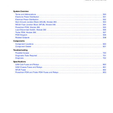
Cascadia Electrical System And Main Pdm Overview
March 2021 0
Microscada System Config Overview
January 2021 0
5. Fio System Overview (
January 2021 0
B767 Electrical System
February 2021 0
Electrical Distribution System Tnb
February 2021 1
Electrical Design System
January 2021 3More Documents from "Shaffiq Ridzuan"