Microscada System Config Overview
This document was uploaded by user and they confirmed that they have the permission to share it. If you are author or own the copyright of this book, please report to us by using this DMCA report form. Report DMCA
Overview
Download & View Microscada System Config Overview as PDF for free.
More details
- Words: 780
- Pages: 14
Loading documents preview...
MicroSCADA System Configuration Overview © ABB Group 20 October 2017
| Slide 1
List of Content
© ABB Group 20 October 2017
| Slide 2
What is: Node, Link, Line and STA
Application Configuration
Base System
Hot-Standby
Watchdog information via SG Tool Menu
Objectives On completion of this module you will be able to:
© ABB Group 20 October 2017
| Slide 3
What is a Node, Link, Line and STA
How an Application Configuration may look like
How the Base System may look like
How the Hot-Standby functionality works
Retrieve watchdog information via SG Tool Menu
Secure Knowledge, Learner activities
Objective:
System Configuration
Time/ Social Form:
Presentation
Reference Documentation:
© ABB Group 20 October 2017
| Slide 4
MicroSCADA Manual
MicroSCADA Configuration Overview
© ABB Group 20 October 2017
| Slide 5
Level 2: Base System Object definition: Node (NOD): Are directly or indirectly connecting base systems to process communication units. A node is primarily specified by the used connection link and the station address of the node.
Links (LIN) A link is a data transmission line to the base system. Link of type LAN: The process communication unit may be directly connected through LAN link. Link of type INTEGRATED: For each configured PC-NET. This link type is used only by PC-NET Several nodes can be connected to the same link and use the same LIN object.
Station (SA) Each Node has a station address which is unique in the entire sys600 system.
MicroSCADA Configuration Overview (BL8) Node, Link, Line and STA Base System 1 SA 9
SNMP
Appl 1
SA 19
STA 101..199 (Nod 11) STA 201..299 (Nod 12) STA 991, 992, 993 (Nod 51, 52, 53) STA 900…989, >1000.. (Nod 19)
STA901..989, >1000 Nod 19
Nod 9 LIN 1 (LAN) LIN 3
Nod 11
© ABB Group 20 October 2017
Nod 12
IEC61850
IEC61850
SA 11
SA 12
STA101..199
STA201..299
LAN
LAN
SA = Station Nod = Node LIN = Link Li = Line | Slide 6
Nod 51
LIN 4
LIN 5
Nod 52
Nod 53
PCNET
PCNET
PCNET
SA 51 STA991
SA 52 STA992
SA 53 STA993
IEC101 Li 1,2
IEC104 Li 3
DNP 3.0 Li 4
MicroSCADA Configuration Overview (
SNMP
Appl 1
SA 115
STA 101..199 (Nod 11) STA 201..299 (Nod 12) STA 991, 992, 993 (Nod 19, 18, 17) STA 900…989, >1000.. (Nod 15)
STA901..989, >1000 Nod 15
Nod 9 LIN 1 (LAN) LIN 3
Nod 11
© ABB Group 20 October 2017
Nod 12
IEC61850
IEC61850
SA 111
SA 112
STA101..199
STA201..299
LAN
LAN
SA = Station Nod = Node LIN = Link Li = Line | Slide 7
Nod 19
LIN 4 Nod 18
LIN 5 Nod 17
PCNET
PCNET
PCNET
SA 119 STA991
SA 118 STA992
SA 117 STA993
IEC101 Li 1,2
IEC104 Li 3
DNP 3.0 Li 4
MicroSCADA Configuration Overview Application Configuration Overview
© ABB Group 20 October 2017
| Slide 8
MicroSCADA Configuration Overview Base System Configuration
© ABB Group 20 October 2017
| Slide 9
MicroSCADA Watchdog Hot-Standby (on startup) SAS 1
SAS 2
1 – On power up WD will supervise the startup
Cold
Cold
2 – After some times faster PC starting is hot
HOT
Cold
HOT
Warm
HOT
Standby
HOT
Cold
(See the state in SemiGraphic Tool Menu/Base System/Application)
3 – PC (Hot) start transferring Application (Note Do not switch off the PC)
4 – When the transferring is done On next power up the WD will keep the same condition.
© ABB Group 20 October 2017
| Slide 10
MicroSCADA Watchdog Hot-Standby (control by Operator) SAS 1
4 – The operator makes a switching from SAS1
HOT
SAS 2
Standby
(SAS2 must be in standby mode)
5 – The WD is supervising the switching
Cold
HOT
6 – PC (Hot) start transferring Application
Warm
HOT
Standby
HOT
7 – When the transferring is done
© ABB Group 20 October 2017
| Slide 11
MicroSCADA Watchdog
Base system config\Applications\appl\Shadowing
© ABB Group 20 October 2017
| Slide 12
MicroSCADA Watchdog
The following three attributes are reported only when the connection to the external base system has been established:
AS: The state of the external application
SS The shadowing state of the external application “WARM_SEND", “HOT_SEND“, “RECEIVE“, “NONE”
SP: The shadowing phase of the external application “TO_WARM_SD", "WARM_SD“, “TO_HOT_SD“, “HOT_SD“, “TO_WARM_RC“, “WARM_RC”, “TO_HOT_RC”, “HOT_RC”, “NONE” See doc Sys600_Application Objects page 183 See doc Sys600_System Objects pages 44,56,57,
© ABB Group 20 October 2017
| Slide 13
"COLD", "WARM“, "HOT"
Related Documents

Microscada System Config Overview
January 2021 0
5. Fio System Overview (
January 2021 0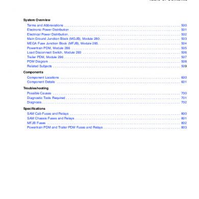
Cascadia Electrical System And Main Pdm Overview
March 2021 0
Absence Evaluation Config
January 2021 0
Config Huawei - Rtn.pdf
January 2021 2
Mach3mill Install Config
January 2021 1More Documents from "Thomas Lunzer"

Sicam Pas - Complete
January 2021 0