The Lakhovsky Mwo
This document was uploaded by user and they confirmed that they have the permission to share it. If you are author or own the copyright of this book, please report to us by using this DMCA report form. Report DMCA
Overview
Download & View The Lakhovsky Mwo as PDF for free.
More details
- Words: 2,123
- Pages: 3
Loading documents preview...
The LokhovskvM[UO: Bock To Squore One Peter R. Lindemonn
+
T
uffiG
Iigure 4 is Sometimes tlle most obvious things take the longest. I arn the schework back reminded of all the wild hype thatsurrounded Tesla's matic of the put forth on in the 1980'sand the crazy new theories tlat were B eck/ B o b how his vireless power systemsuPPosedlyoperated. Smeuing Klark Kent a rubber fuh in the pan, BSRF railed against tre madness and Figure I I\{!VO (sirneventually released a video presentation of Tesla's wireless phffed). After power system in action. Remarkably, all it took was the genius studying these circuits for a wbile, I realized that there were a of Eric Dollard and going ba.ckto Tesla'sfatent.Tlte model bujlt number ofbasic diflerences. Lakhovsky had plac ed the spark gap from dre parent performed as claimed. No new theories or and the capacitor iI] a different relationship in t]re middle section explanadonswere needed. This video, Teslats lrngitudiof the circuit than Tesla and the others. Could this be important? is prool enough tlat going back to the nal Electricity Lakhovsky had also stepped the volage down in the ffnal stage original design is the best place !o starl when n-ying to underof the circuit where Tesla and ttre othen all stepped the voltage stand,or duplicalcsomeone's work, So, tlre question is, has anyone ever tried to duplicale way up . Was this signiffcant? What was Lakhovsky trying ta do thar was different tran what Tesla was t-ying to do? La.klovsky's I\{!VO as it is described in his patenr? After ffnally 'l"here were some other tlings that also puzded me. Both The read *rough I careitlly the right question, asking myself and Tesla had well developed subde sensi[vities Lakhovsky flandbook Wave Oscillator Multiple Lalrhovsky a pendulum to help him in his design work and Lal,drovs\ used single interesling. Every is quite I forurd for the answer. \Vhat sensory abilities are menlioned tlroughout Tesla's expanded Lakhovsky's for *re book, except in MWO schematic printed t}le writings of his biographers. Because of thb, writings and Tesla's his one of va.riation on patent diagram, is a model of or a that of their electrotherapeutic devices were I both years, assume for the last 30 electrGtherapeutic devicesl It seems that to near, even to very sensitivepeople, like be totally benign people have just be en putting Lakholsky's famous multi-ringed this becausenothingleaves my laboratory themselves. I assume anterura at t}Ie end of a Tesla circuit atrd fiinking tiat they had like. ExPeriments I have run strongly personally that I don't rhe real rhing. All of tlese unis. vaiiacioruon a circuit presented that cause seDsitivepeople to be tlrat a]l of the efiece the suggest by Bob Beck in 1963,spark proftrsely between the rings of style MWO) come from the (Becly'Kent these rnfts iritated by atrtenna.tsob has repeatedly told experimenters to bujld their the anterura. This brings up the the rings of sparking betl'reen MWOs with more and more power so that they will produce ques[on of whether or not tle MWO a.ntennais supposed to iDcreasing anounts of sparking on the anaerura.Oru ffles contain letters from people who report excellent results ftom these spark. Tesla is very clear in his writing tlat his units worked rnuch better when all electrical discharges from the terminals devices.The accolades.however, have notbeen universal.The were suppressed.At one point, he even describeswing 2 inches big problern with this style of MWO is that people who are of wax to cover the teminals (antennas).Likewise, Lakholsky seLsitive!o subtle energy, Iike myself, can't stand to be in the same room with one of thern whjle drey are operating because never mentions sparking dischargesbetween the rings of his alteruras.Somephotos showabn$h or coronadischargeoll the they are so irritating. Something was not right in all of this, and outermost ring of his MWO I wanted to ffgure it out. altennas, but no mention is problem, I To illustrate the made of this being the normal have included foru schematic therapeulic operating mode. diagrams here for reference. AJso, no photo of Lakhorsky's ligu,re I is the schematic o[ show arcing 6a' MWOs ever I-alhovsky's MWO ta]<enfrom In light oI this, tie rings. tprrn his parenr. Figure 2 is a sche that th Tesla ed bo I arn c onvinc maric caken from an article by their Lakhovsky designed and Tesla on bis electrGtherapeutic this to eliminate bedevices experiments. Figure 3 is the I havior. I stongly believe tlnt schematic for a "bigb power a La}
E blt
1993,Page43 Borderlandr 1stQuarter
A mG!-P'otE&
llULTl-lrVE
OSCILLTTOn
'" '" )k,8.tl*
t - s".on-ry
? 0 l u f n . 1"orr, 23 etrcl u€avy Inrulst€d
9 turrg #la rtre,
hrt 2 .ad turar .pr.ad out to Va h, b.tre€n turnr.
t .0015 ltF Crprclior (cond6n!sr)
shtl. Iay.r round RllhoLe to soak up at€sp rav. froot fro! codden..r dt}cba!96 acro.. Aap aaal porslbly Ie€p lt lror puacturirt lnlulatlon
ol .nd turns oi forn.r rldaliar.
<- to Iv - 250 vA Trar.lorrer
trarsC
75 *stt
laq
Ll.5VCbousscurr€Dt.
Figure 3 between the rings of the antenna. Having resolved these issues to my own satisfaction, I decided that the only way to ffnd out the rest of the lacts was to acnrally build a circuit drat behaved like the circuit in Lakhorsky's patelt. To do this I had to decide what components to use, as no parts values are given in the patent. Even if they were, these parc would not be available today. What io do? ln Figure l, Laklovsky begirx by powering the primary coil of a traruformer on DC (direct current) that is rapidly int€rrupted by a device he callsa "trembler" (V in Figure l). The purpose and finction of this trembler is to provide a sequence of DC puJsesto the prirnary of the transformer by mechanically making and breaking the DC power feed to the primary whding. I decided that one of Klark Kent's 12VDC power supplies&iving the primary of an automobile ignition coil interrupted by a solid state transistor circuit was a suitable modem substihrte. It performed the same fi.urctions that La}hovsky speciffes in ttre patent. I 'acquired'one of Klark Kent's MWO unis from the Borderland collection and went to work. Besides ttre ffrst stage power supply driving the primary of the coil, everything else in the Klark Kent MWO was essentially a Tesla ctcuit, so I took it apart. I rernoved the high voltage output coil completely and rewired the capacitors and spark-gap so that f}ley were in the right place in the circuit according to 'Ihe Lakhovsky. Ll and L2 output coils I decided to build, since
no suitable replacements were available. Without ary clear directiom from the palent about ttre proper dimensioru for these coils, I actually had to liiz,t about it. Small, tightly wound coils usually block high frequency signals and, for this reason, are sometimes called "chokes". Obviously, these coils were not supposed to be extremely small beca.usepassing a wide spectrum of high frequency currents was their purpose. By cortrast" one of Tesla's designs speciffes a 2 foot diameter coil set in this location in the output. But photos of Lakhorsky's MWOs clearly show no coils that large. I decided io y/ind two coils about 2 inches in dianeter !o begin my experimens. Ll, the primary, I wound with 7 urrns of bare #18 single strand copper wire. The hrrns a.reabout lp of an inch apad and stand free in the open air with no dielectric material or coil form near'by. L2, the secondary, is only 5 urrns of similar wire and dimension. The h,/o coils are placed end io end about an incb apart. The ends of L2 are connected to rings I and 2 of the prinied circuit board MWO anterun developed by Eric Dollard and BSRI, as iUushated in Lakhovsky's patent. Ll is connected to the capacitor and the spark-gap. Awesome! I was ffnally in possession of a reasonable facsimile of a real Lal
Borderlauds 1stQuarler1993,Page,l4
Figure 4
ECG{I3
SOUI}STAIE cot{TRoL
SOUI}STATE coitTRoL
Flgure 5 capacitor discharge creaies a very difierent kind of "spark" than an inductive collapse. (Anyone not understanding this should watch the 6rst 20 minutes of the BSRF video Free Energy Research,Init Eric Dollard demonstratesboth inductive and capacitive arcs ald discnsses the differences betrveen them.) The Becl,rKent sgvle of MWO uses the circuit primarily as a source ofhigh voltage to produce arcing bet'aeen the rings of the antenna. The various lengths of sparks at the antenna become the source of the wide spectrum offrequenciesproduced by the device.While thismethod mayproduce the requted wide band of emissions,it \easnot the method Lakhorsky was working on. The patent is dear ou this poin! Lakhorsky envisioned the capaciior discharge as the source of his wide spectrum of ftequencies and dre multi-ringed antenna as a resonator s)€tem to draw out even more aad higher harmonics by induction. As uual, the simple ueation of multiple frequencies is not enough. The subtle naoue ofthese frequenciesand how they are created is also inporta-ol Many experimens need to be tried on all of the possible nethods of drivmg the anterma that are covered by the patent. Beyond tbat, the patent describes using or y one antenn4 whereas all of the photos of Lakhovsky's MWOs show him rsing hvo antennas. The exact alterura hook-up is still urknowrt. I have no*' &iven the altenna bodr electro+tatically, asspeciffed in the patent (ngrue 5), and electromagnetically by eliminating ECG5r3
Flgure 5
Ll & I2 and direcdy connecting the outer ring of the anteDnain the place ofLl (Figure 6). The efiects subjectively seem shonger in the direct connectionmode, but both are gende and penetrating. I have also driven two phi ratio spiral anteryras ill the elechcstatic mode facing each otler, each spiral connecied at its center to one end of [2 (Figue 7). The effectsin the space behveenthe two antennasare tJremostpowerfrrl I have seenyet. While use of these golden section spirals is a deviafon from Lakhorsky's designs, the conffguration of usitrg two antennas to set up an area of high frequency electrostatic oscillatioDs between them was his intent, it seems.The effect in the area between lhe anterurasis quite skong and lends credence to the 'l-esla electro-static mode of operation, also experimented with the which he called terminals (t) this method of driving antennas as shown in Figure 8. He used large copper plates for these terminals, and assuch, did not expect them to augment the total frequenry response of tle s)stem as Lakhovsky djd with his multi-ringed antelmas. My experiments suggestthat when using one antenn4 the electro-magnetic hook-up is t}le shongest, asin Lakhorsky's RCO chcuis. When using two ant€nnas, the electastatic hook-up is the strongesl as in Lakhorsky's MWO circuits. In futrue articles, I plan to address the construction of a real Lakhowky MWO anbnnamade from copper tubes stspended on silk threads asspecified in the patent. I believe that the copper rings, rurencumbered by fie proximiy of any dielectric material, will be able to 'ring' Aeely up into the very high harmonics La.khorsky euvisioned. Thls could be the 6nal 'improvement' necessary to get us all the way back to where Lakhorsky was in 1931.The design for the real MWO may have been with us all along. Sometimes the most obvious things take the longest.
SOLI}STATE cotaTRoL
Figure 7 Borderlandr 1stQuarte|I993,Page45
Related Documents

The Lakhovsky Mwo
January 2021 0
Lakhovsky Mwo Handbook - Thomas J. Brown
January 2021 0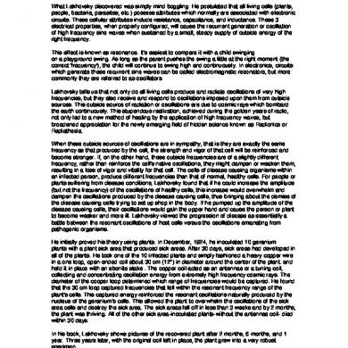
Mwo
January 2021 6

Mwo Review
January 2021 1
Mwo Brochure
January 2021 1More Documents from "AWR Corporation"