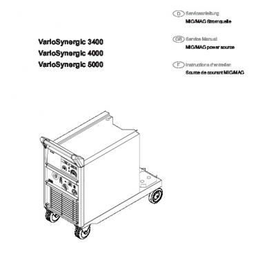
Variosynergic 3400 Variosynergic 4000 Variosynergic 5000: Serviceanleitung D
This document was uploaded by user and they confirmed that they have the permission to share it. If you are author or own the copyright of this book, please report to us by using this DMCA report form. Report DMCA
Overview
Download & View Variosynergic 3400 Variosynergic 4000 Variosynergic 5000: Serviceanleitung D as PDF for free.
More details
- Words: 3,418
- Pages: 9
Loading documents preview...
D
Serviceanleitung MIG/MAG Stromquelle
VarioSynergic 3400
GB Service Manual MIG/MAG power source
VarioSynergic 4000 VarioSynergic 5000
F
Instructions d‘entretien Source de courant MIG/MAG
42,0410,0516
012003
Sehr geehrter FRONIUS-Kunde
Dear FRONIUS-customer
Die vorliegende Broschüre soll Sie mit den SETUP-FUNKTIONEN vertraut machen. Es liegt in Ihrem Interesse, die Bedienungsanleitung aufmerksam zu lesen, und die hier angegebenen Weisungen gewissenhaft zu befolgen. Sie vermeiden dadurch Störungen durch Bedienungsfehler. Das Gerät wird Ihnen dies durch stete Einsatzbereitschaft und lange Lebensdauer lohnen.
This brochure is intended to familiarise you with the SETUPFUNCTIONS. It goes without saying that it is in your own interest to read the brochure carefully and follow the instructions given exactly - so as to prevent malfunctions and operating errors. This will help to ensure that your welding machine continues to give you constant service for years to come.
Die Inbetriebnahme des Gerätes darf nur durch geschultes Personal und nur im Rahmen der technischen Bestimmungen erfolgen. Der Hersteller übernimmt für Schäden, die durch unsachgemäßen Einsatz und Bedienung entstehen, keinerlei Haftung. Vor Inbetriebnahme unbedingt GeräteBedienungsanleitung lesen.
The machine may only be started up by trained personnel, and only as stipulated in the technical directions. The manufacturer will accept no liability for damage caused by improper use or operation. Read the operating instructions before putting the machine into service.
Hinweis -Zeichen Die von FRONIUS hergestellten Geräte erfüllen die Konformitätsanforderungen des CE-Zeichens.
Mark N.B.All FRONIUS-manufactured equipment meets the conformity requirements of the CE mark.
Für Instandhaltungs- und Überholungsarbeiten verwenden Sie nur Original-FRONIUS-Ersatzteile. Unser Kundendienst, welcher über fachmännisch geschultes Personal, geeignete Mittel und Einrichtungen verfügt, steht Ihnen selbstverständlich gerne zur Seite.
Always use only original FRONIUS spare parts for maintenance and overhaul work. Our after-sales service department - with its highly trained staff and specialist resources and facilities - will be pleased to assist you at all times.
Fronius International GmbH
Fronius International GmbH
ERSATZTEILBESTELLUNG Bei Bestellung geben Sie bitte die genaue Benennung und die dazugehörige Sach-Nummer laut Ersatzteilliste an. Für eine problemlose Ersatzteillieferung benötigen wir unbedingt die Fabrikations-Nummer Ihres Gerätes. Diese lesen Sie am Leistungsschild ab.
ORDERING SPARE PARTS When ordering spare parts please state the exact designation and the relevant item number, as given in the spare parts list. To ensure that we supply you with exactly the right spare parts we must have the serial number of your machine. You can find this on the rating plate.
INHALTSVERZEICHNIS Setup-Menü ______________________________________ 3 Error-Anzeigen ____________________________________ 3 Verkaufs- und Serviceniederlassungen
TABLE OF CONTENTS Set-Up Menü Error Indications Scales and service offices
Text und Abbildungen entsprechen dem technischen Stand bei Drucklegung. Änderungen vorbehalten. Text and illustrations correct at time of going to print. Right of alteration is reserved.
1
4 4
Cher client de FRONIUS, La brochure présente est destinée à vous familiariser avec la FONCTIONS SETUP. C’est dans votre intérêt de lire attentivement le mode d’emploi et d’observer scrupuleusement les instructions y mentionnées. Ainsi vous éviterez des pannes dues à des fautes de manipulation. L’appareil vous en récompensera par une disponibilité permanente et une longue vie. L’appareil ne doit être mis en service que par du personnel formé et seulement dans le cadre des dispositions techniques. Le fabricant ne sera pas responsable de dommages dus à un emploi ou une manipulation non convenable. Avant la mise en service, il est essentiel de lire la mode d´emploi.
Remarque signe Les appareils produits par FRONIUS remplissent les exigences de conformité du signe CE. Pour les travaux d’entretien et de réparation il ne faut utiliser que des pièces de rechange originales de FRONIUS. Notre service après-vente avec son personnel expert, ses moyens appropriés et ses installations sera évidemment toujours à votre disposition.
Fronius International GmbH
COMMANDE DE PIÈCES DE RECHANGE Lors d’une commande nous vous prions de désigner exactement la pièce commandée et d’indiquer le numéro de référence correspondant suivant notre liste de pièces de rechange. Pour une livraison de pièces de rechange sans problèmes nous avons absolument besoin du numéro de fabrication de votre appareil. Vous trouverez ce numéro sur la plaque signalétique.
SOMMAIRE Le menu d´initialisation (Set-up) Les codes d´erreur Bureaux de vente et bureaux de service
5 5
Texte et illustrations correspondent à la date de mise sous impression. Modifications réservées.
2
Bedienelemente auf Funktion prüfen Wahlschalter Betriebsart in Stellung
DAS SETUP-MENÜ Hinweis: Sämtliche Arbeiten dürfen nur von geschultem Fachpersonal durchgeführt werden.
Wird ein Bedienelement betätigt, erscheint am linken Display die Eingangsleitspannungsnummer (z.B. L 04) und am rechten Display ein Spannungswert zwischen 0 und 5V. Wird das Bedienelement verändert, muß sich die rechte Anzeige ändern. Falls nicht, liegt ein Defekt des Bedienungselementes vor.
Einstieg in das Setup-Menü l Stromquelle einschalten l innerhalb der ersten zwei Sekunden den Einstellregler Drahtgeschwindigkeit dreimal vom linken zum rechten Anschlag drehen
Eingangsnr. L 01 L 02 L 04 L 05 L 06 L 07 L 08 L 09 L 10
Die Stromquelle bestätigt den Einstieg in das Setup-Menü durch dreimaliges Blinken aller Anzeigen. Mit dem Wahlschalter Betriebsart können nun die gewünschten Setup-Funktionen angewählt werden.
Versions-Check durchführen Wahlschalter Betriebsart in Stellung
schalten
schalten l Wahlschalter Digitalanzeige in Stellung linkes Display: Eprom-Nummer (z.B. "005"). rechtes Display: Software-Version (z.B. "3.00") l Wahlschalter Digitalanzeige in Stellung schalten linkes Display: max. Motor-Sollspannung rechtes Display: Maschinenerkennung (z.B. "500" - im Fehlerfall zeigt das linke Display "E41" an l Wahlschalter Digitalanzeige in Stellung schalten rechtes Display: Version des Steuerprints (z.B. "1") linkes Display: Version des Anzeigenprints (z.B. "2")
L 11 L 12 L 13 L 14 L 15 H 18 H 19 H 20
Maximale Motordrehzahl einstellen Wahlschalter Betriebsart in Stellung
H 21 schalten
l rechtes Display: Sollwert der Motordrehzahl (max. 18 m/min) l linkes Display: Motorleerlaufspannung in Volt
Bezeichnung Werte-Bereich Schweißstrom-Istwert 0-5 V Schweißspannung-Istwert 0-5 V Vorschubmotor-Sollwert 0-5 V Feinstufenschalter 0-5 V Grobstufenschalter 0-5 V Wahlschalter Digitalanzeige 0-5 V Wahlschalter für Drahtdurchmesser 0-5 V Wahlschalter Schweißprogramm 0-5 V Einstellregler Intervall-Schweißzeit bzw. Punktierzeit 0-5 V Einstellregler Nachbrennzeitkorrektur 0-5 V Einstellregler Intervall-Pausenzeit 0-5 V Einstellregler Gasvorströmzeit 0-5 V Einstellregler Gasnachströmzeit 0-5 V Einstellregler Anschleichgeschwindigkeit0-5 V Brennertaste 0.00 V = On 5.00 V = Off Externer Reset 0.00 V = On 5.00 V = Off Übertemperatur 0.00 V = On 5.00 V = Off Select (nur intern verwendet) 0.00 V = On 5.00 V = Off
Ausstieg aus dem Setup-Menü l Stromquelle ausschalten
Wichtig: Motordrehzahl erst einstellen, wenn der Motor Betriebstemperatur erreicht hat!
DIE ERROR-ANZEIGEN
Einstellen der Motordrehzahl: l Brennertaste drücken - Motor beginnt mit der maximalen Drehzahl zu laufen l Mit einem Drehzahlmeßgerät an der Antriebswelle des Vorschubmotors die Drehzahl messen und gegebenenfalls auf 186 U/min einstellen - mit dem Einstellregler Anschleichgeschwindigkeit kann eine grobe Korrektur von +/- 12,5%, mit dem Einstellregler Nachbrennzeitkorrektur eine feine Korrektur von +/- 2,5% vorgenommen werden l Brennertaste loslassen - Einstellungen werden gespeichert
Abgleich Digitalanzeige Wahlschalter Betriebsart in Stellung
(Punktieren) schalten
Alle Error-Anzeigen können entweder durch Drücken der Brennertaste oder Ein/Aus-Schalten der Stromquelle resetiert werden! Error-Nummer E 02 E 03 E 35 E 37 E 39 E 40
schalten
E 41 E 42
l Wahlschalter Schweißprogramm auf Stellung "Manuel": Abgleich der Stromanzeige l Wahlschalter Schweißprogramm auf Stellung "CO2 100%": Abgleich der Spannungsanzeige Für weitere Informationen fordern Sie bitte die Justieranweisung VS 3400/4000/5000 mit der Dokumentennummer JA-PMÜ-02 an.
3
Fehlerbeschreibung Interner Fehler (Fehler beim AD-Wandler) Betriebswahlschalterstellung ist im SetupMenü nicht belegt Eprom ist nicht für Printversion geeignet Überstrom Vorschubmotor Übertemperatur Externer Reset - Anlage wurde durch einen externen Reset gestoppt Fehler in der Maschinenerkennung Überstrom im Sekundärkreis (Schweißkreis und Brennerleitung auf Kurzschluß prüfen)
Check controls for correct operation Switch operating-mode selector switch in position welding)
THE SET-UP MENU Note: Any work to be carried out may only be done by trained skilled personnel.
(spot
After having operated a control element, the input voltage conductance (e.g. L 04) is shown on the left display and a voltage value between 0 and 5V on the right-hand display. If the control element is modified, the right-hand display must change also. If not, the control element is defective.
Accessing the set-up menu l Switch the power source on l Rotate the wire-speed controller three times from the left to the right-hand stop end within the first three seconds
Input no L 01 L 02 L 04 L 05 L 06 L 07 L 08 L 09 L 10
The displays of the power source flash three times to confirm the access to the set-up menu. Then, it is possible to select the requested set-up functions by means of the operating-mode selector switch. Checking the version no: Switch operating-mode selector switch in position l Switch digital-display selector switch in position Left-hand display: Eprom number (e.g. ”005”) Right-hand display: software version (e.g. ”3.00”) l Switch digital-display selector switch in position Left-hand display: maximum motor voltage command value Right-hand display: machine recognition (e.g. "500" - "E41" is shown on the left-hand display in the case of an error ) l Switch digital-display selector switch in position Right-hand display: control board version number (e.g. ”1”) Left-hand read-out: display board version number (e.g. ”2”)
L 11 L 12 L 13 L 14 L 15 H 18
Setting the maximum motor speed Switch operating-mode selector switch in position
H 19 H 20
l Right-hand read-out: motor speed command value (max. 18 m/min) l Left-hand read-out: open-circuit motor voltage
H 21
Description Values range Actual welding-current value 0-5 V Actual welding-voltage value 0-5 V Wirefeed-motor command value 0-5 V Fine-regulating switch 0-5 V Coarse-step control switch 0-5 V Digital-display selector switch 0-5 V Wire-diameter selector switch 0-5 V Welding-program selector switch 0-5 V Interval welding time and spot welding time regulator 0-5 V After-burn time correction 0-5 V Interval off-period regulator 0-5 V Gas preflow time regulator 0-5 V Gas post-flow regulator 0-5 V Inching-speed regulator 0-5 V Torch trigger 0.00 V = On 5.00 V = Off External reset 0.00 V = On 5.00 V = Off Over temperature 0.00 V = On 5.00 V = Off Select (only used internally) 0.00 V = On 5.00 V = Off
Important: Do not set the motor speed until the motor has reached operating temperature! Setting the motor speed: l Press the torch trigger - the motor begins to run at maximum speed l Use a speed indicator to measure the speed at the driving shaft of the wirefeed motor and set to 186 rpm, if necessary - use the inching-speed controller to correct roughly by +/- 12.5%, use the after-burn time controller to correct accurately by +/- 2.5% . l Release the torch trigger. The settings will now be stored.
Exiting the set-up menu l Switch off the power source
Digital display adjustment Switch operating-mode selector switch in position
Input no E 02 E 03
ERROR INDICATIONS All error indications can be reset by either pressing the torch trigger or switching the power source off and back on again.
l Switch welding program selector switch in position "manual": Amperage display is adjusted l Switch welding program selector switch in position "CO2 100%": Voltage display is adjusted
E 35 E 37 E 39 E 40
For further information please refer to the VS 3400/4000/5000 Adjustment Instructions with the document number JA-PMÜ-02.
E 41 E 42
4
Description of error Internal error (error of the A/D-converter) No function has been assigned to this position of the operating-mode switch in the set-up menu Eprom not suitable for this version of the pcboard Wirefeed motor: Overcurrent Overtemperature External reset - machine has been stopped by an external reset Machine recognition error Excess current in secondary circuit (check welding circuit and torch lead for shorting)
Pour d'autres informations, prière de demander les instructions d'ajustage VS 3400/4000/5000 portant le numéro de document JA-PMÜ-02.
LE MENU D’INITIALISATION (SET-UP) Remarque : seuls les techniciens qualifiés sont autorisés à effectuer des travaux sur l'appareil.
Vérifier le fonctionnement des organes de commande Mettre le sélecteur de mode sur la position (soudage par points)
Démarrage du menu d’initialisation l Mettre le générateur de soudage en circuit. l Au cours des deux premières secondes, tourner trois fois le régulateur de la vitesse du fil depuis la butée de gauche jusqu'à la butée de droite.
Lorsqu'un des organes de commande est actionné, le numéro de la tension de commande s'affiche sur l'indicateur de gauche (p. ex. L 04) et une valeur de tension entre 0 et 5 V apparaît sur l'indicateur de droite. Lorsque l'organe de commande change, l'affichage de droite doit également changer. Si ce n'est pas le cas, l'organe de commande présente un défaut.
Le générateur de soudage confirme l'entrée dans le menu d'initialisation par trois clignotements des indicateurs. Les fonctions d'initialisation peuvent ensuite être sélectionnées à l'aide du sélecteur de mode.
N° de l´organe Désignation Plage de valeurs de commande L 01 Valeur réelle du courant de soudage 0-5 V L 02 Valeur réelle de la tension de soudage 0-5 V L 04 Valeur de consigne du moteur du dévidoir0-5 V L 05 Commutateur de réglage fin 0-5 V L 06 Commutateur de réglage grossier 0-5 V L 07 Sélecteur de l'indicateur numérique 0-5 V L 08 Sélecteur du diamètre du fil 0-5 V L 09 Sélecteur du programme de soudage 0-5 V L 10 Régulateur de l'intervalle des temps de soudage ou de pointage 0-5 V L 11 Régulateur correction du temps de postcombu stion 0-5 V L 12 Régulateur de l'intervalle des temps de pause 0-5 V L 13 Régulateur du temps de prédébit de gaz 0-5 V L 14 Régulateur du temps de postdébit de gaz0-5 V L 15 Régulateur de la vitesse d'approche 0-5 V H 18 Gâchette de la torche 0.00 V = On 5.00 V = Off H 19 Reset externe 0.00 V = On 5.00 V = Off H 20 Surchauffe 0.00 V = On 5.00 V = Off H 21 Select (utilisé uniquement en interne)0.00 V = On 5.00 V = Off
Vérification des numéros de version Mettre le sélecteur de mode sur la position l Mettre le sélecteur d'indicateur numérique sur la position Indicateur de gauche : numéro d’EPROM (par exemple "„005") Indicateur de droite : version du logiciel (par exemple "3.00") l Mettre le sélecteur d'indicateur numérique sur la position Indicateur de gauche : tension de consigne max. du moteur Indicateur de droite : identification de la machine (p. ex. "500" - en cas d'erreur, l'indicateur de gauche affiche "E41". l Mettre le sélecteur d'indicateur numérique sur la position Indicateur de droite : version de la carte de commande (p. ex. "1") Indicateur de gauche : version de la carte d’affichage (p. ex. "2")
Ajustage de la vitesse maximale du moteur Mettre le sélecteur de mode sur la position l Indicateur de droite : valeur nominale de la vitesse d’avance du fil (max. 18 m/min) l Indicateur de gauche : tension à vide du moteur (en volts) Important : n’ajuster la vitesse du moteur que lorsque celui-ci a atteint sa température normale de fonctionnement !
Pour quitter le menu d’initialisation: l Mettre le générateur de courant hors circuit
Ajustage de la vitesse du moteur : l Presser la gâchette de la torche. Le moteur démarre à plein régime l Relever la vitesse du moteur du dévidoir sur l'arbre d'entraînement à l'aide d'un tachymètre et la régler au besoin sur 186 tr/min. Le régulateur de la vitesse d'approche permet d'effectuer une correction grossière de +/- 12,5%, le régulateur du temps de postcombustion une correction précise de +/2,5%. l Lâcher la gâchette de la torche. Les réglages sont enregistrés en mémoire.
LES CODES D’ERREUR Tous les codes d’erreur peuvent être effacés, soit en pressant la gâchette de la torche, soit en actionnant l’interrupteur secteur ! N° d´erreur E 02 AD) E 03
Réglage des indicateurs numériques Mettre le sélecteur de mode sur la position
E 35 E 37 E 39 E 40
l Sélecteur du programme de soudage sur la position "manuel": ajustage de l’affichage de courant l Sélecteur du programme de soudage sur la position "CO2 100%": ajustage de l’affichage de tension
E 41 E 42
5
description de la panne panne interne (erreur dans le convertisseur position du commutateur de fonctions non utilisée dans le menu d´initialisation EPROM inadaptée à la version de la carte surintensité dans le moteur d'entraînement température excessive reset externe : l'appareillage a été stoppé par un reset externe erreur d'identification de la machine surintensité de courant dans le circuit secon daire (vérifier s'il n'y a pas de court-circuit dans le circuit de soudage ou dans la ligne de la torche)
6
Fronius Worldwide - www.fronius.com/addresses A
FRONIUS International GmbH 4600 Wels, Buxbaumstraße 2 Tel: +43 (0)7242 241-0 Fax: +43 (0)7242 241-3940 E-Mail: [email protected] http://www.fronius.com
CZ
709 00 OSTRAVA - Mariánské Hory, Kollárova 3 Tel: +420 595 693 811 Fax: +420 596 617 223 E-Mail: [email protected]
4600 Wels, Buxbaumstraße 2 Tel: +43 (0)7242 241-0 Fax: +43 (0)7242 241-3490 Service: DW 3070, 3400 Ersatzteile: DW 3390 E-Mail: [email protected]
760 01 ZLÍN ul. Malá (za èerp. st. ARAL) Tel: +420 577 311 011 Fax: +420 577 311 019 E-Mail: [email protected]
6020 Innsbruck, Amraserstraße 56 Tel: +43 (0)512 343275-0 Fax: +43 (0)512 343275-725 5020 Salzburg, Lieferinger Hauptstr.128 Tel: +43 (0)662 430763 Fax: +43 (0)662 430763-16 1100 Wien, Daumegasse 7, Team Süd / Ost Tel: +43 (0)1/600 41 02-7410 Fax: +43 (0)1/600 41 02-7490 Team Nord / West Tel: +43 (0)1/600 41 02-7050 Fax: +43 (0)1/600 41 02-7160
Haberkorn Ulmer GmbH 6961 Wolfurt, Hohe Brücke Tel: +43 (0)5574 695-0 Fax: +43 (0)5574 2139 http://www.haberkorn.com
Wilhelm Zultner & Co.
90530 Wendelstein, Wilhelm-Maisel-Straße 32 Tel: +49 (0)9129 2855-0 Fax: +49 (0)9129 2855-32 51149 Köln, Gremberghoven, Welserstraße 10 b Tel: +49 (0)2203 97701-0 Fax: +49 (0)2203 97701-10 57052 Siegen, Alcher Straße 51 Tel: +49 (0)271 37515-0 Fax: +49 (0)271 37515-15
10365 Berlin, Josef-Orlopp-Str. 92-106 Tel: +49 (0)30 557745-0 Fax: +49 (0)30 557745-51
Av. Senador Vergueiro, 3260 Vila Tereza, Sao Bernado do Campo - SP CEP 09600-000, SÃO PAULO Tel: +55 (0)11 4368-3355 Fax: +55 (0)11 4177-3660 E-Mail: [email protected]
Tel: +41 (0)1817 9944 Fax: +41 (0)1817 9955 E-Mail: [email protected]
FRONIUS Èeská republika s.r.o. 381 01 ÈESKÝ KRUMLOV, Tovární 170 Tel: +420 380 705 111 Fax: +420 380 711 284 E-Mail: [email protected] 100 00 PRAHA 10, V Olšinách 1022/42 Tel.: +420 272 111 011, 272 742 369 Fax: +420 272 738 145 E-Mail: [email protected] 315 00 PLZEÒ-Bo•kov, Letkovská 38 Tel: +420 377 183 411 Fax: +420 377 183 419 E-Mail: [email protected] 500 04 HRADEC KRÁLOVÉ, Pra•ská 293/12 Tel.: +420 495 070 011 Fax: +420 495 070 019 E-Mail: [email protected]
FRONIUS France SARL
N
FRONIUS Norge AS
SK
67661 Kaiserslautern, Liebigstraße 15 Tel: +49 (0)631 35127-0 Fax: +49 (0)631 35127-50 E-Mail: [email protected]
Wilhelm Zultner & Co.
FRONIUS do Brasil LTDA
F
FRONIUS Deutschland GmbH
38640 Goslar, Im Schleeke 108 Tel: +49 (0)5321 3413-0 Fax: +49 (0)5321 3413-31
Schweiz AG CH FRONIUS 8153 Rümlang, Oberglatterstraße 11
CZ
D
8042 Graz, Schmiedlstraße 7 Tel: +43 (0)316 6095-0 Fax: +43 (0)316 6095-80 Service: DW 325, Ersatzteile: DW 335 E-Mail: [email protected]
9020 Klagenfurt, Fallegasse 3 Tel: +43 (0)463 382121-0 Fax: +43 (0)463 382121-40 Service: DW 430, Ersatzteile: DW 431 E-Mail: [email protected]
BR
586 01 JIHLAVA, Brnìnská 65 Tel: +420 567 584 911 Fax: +420 567 305 978 E-Mail: [email protected]
60306 SENLIS CEDEX, 13 avenue Félix Louat - B.P.195 Tél: +33 (0)3 44 63 80 00 Fax: +33 (0)3 44 63 80 01 E-Mail: [email protected]
3056 Solbergelva, P.O. BOX 32 Tel: +47 (0)32 232080, Fax: +47 (0)32 232081 E-Mail: [email protected]
FRONIUS Slovensko s.r.o. 917 01 Trnava, Nitrianská 5 Tel: +421 (0)33 590 7511 Fax: +421 (0)33 590 7599 E-Mail: [email protected] 974 03 Banská Bystrica, Zvolenská cesta 14 Tel: +421 (0)48 472 0611 Fax: +421 (0)48 472 0699 E-Mail: [email protected]
UA
FRONIUS Ukraine GmbH 07455 Ukraine, Kiewskaya OBL.., S. Knjashitschi, Browarskogo R-NA Tel: +38 044 94-62768 +38 044 94-54170 Fax: +38 044 94-62767 E-Mail: [email protected]
USA LLC USA FRONIUS 10503 Citation Drive, Brighton, Michigan 48116 Tel: +1(0) 810 220-4414 Fax: +1(0) 810 220-4424 E-Mail: [email protected]
21493 Talkau, Dorfstraße 4 Tel: +49 (0)4156 8120-0 Fax: +49 (0)4156 8120-20 70771 Leinfelden-Echterdingen (Stuttgart), Kolumbus-Straße 47 Tel: +49 (0)711 782852-0 Fax: +49 (0)711 782852-10 04328 Leipzig, Riesaer Straße 72-74 Tel: +49 (0)341 27117-0 Fax: +49 (0)341 27117-10 01723 Kesselsdorf (Dresden), Zum alten Dessauer 13 Tel: +49 (0)35204 7899-0 Fax: +49 (0)35204 7899-10 67753 Hefersweiler, Sonnenstraße 2 Tel: +49 (0)6363 993070 Fax: +49 (0)6363 993072 18059 Rostock, Erich Schlesinger Str. 50 Tel: +49 (0)381 4445802 Fax: +49 (0)381 4445803 81379 München, Gmunder Straße 37a Tel: +49 (0)89 748476-0 Fax: +49 (0)89 748476-10 83308 Trostberg, Pechleraustraße 7 Tel: +49 (0)8621 8065-0 Fax: +49 (0)8621 8065-10 94491 Hengersberg, Donaustraße 31 Tel: +49 (0)9901 2008-0 Fax: +49 (0)9901 2008-10
Under http://www.fronius.com/addresses you will find all addresses of our sales branches and partner firms! ud_fr_st_so_00082
022006
Related Documents

3400 Hui
February 2021 1
5000-structure.pdf
January 2021 0
Calculo 4000
January 2021 1
Common Rail Series 4000
January 2021 1