Iqwq Ce Bpimp 00 0901 C
This document was uploaded by user and they confirmed that they have the permission to share it. If you are author or own the copyright of this book, please report to us by using this DMCA report form. Report DMCA
Overview
Download & View Iqwq Ce Bpimp 00 0901 C as PDF for free.
More details
- Words: 8,774
- Pages: 34
Loading documents preview...
EPC Contractor
WEST QURNA I SECTION 2
PHASE II CRUDE TANKAGE, PUMPS & METERS (127) PROJECT INFORMATION MANAGEMENT PLAN 00 - COMMON OVERALL - ALL AREAS IQWQ-CE-BPIMP-00-0901
Rev.
Date
Description
Prepared By
Verified By
Approved By
A
11-NOV-2014
Issued for Internal Review
J. Zhilan
Z. Xuewen
R. Gangfeng
B
30-NOV-2014
Issued for Review & Comments
J. Zhilan
Z. Xuewen
R. Gangfeng
C
08-FEB-2015
Issued for Review & Comments
R. Kurian
Z. Xuewen
R. Gangfeng
IQWQ-CE-BPIMP-00-0901
Project Information Management Plan
08-MAR-2015
TABLE OF CONTENTS 1.0 2.0 3.0
4.0 5.0
6.0 7.0
8.0 9.0
SCOPE ......................................................................................................................................................... 2 REFERENCES ............................................................................................................................................. 3 DEFINITION AND ABBREVIATION ............................................................................................................ 3 3.1 Definition ....................................................................................................................................... 3 3.2 Abbreviation .................................................................................................................................. 4 PROJECT IDENTIFICATION ....................................................................................................................... 4 ORGANIZATION AND RESPONSIBILITIES .............................................................................................. 4 5.1 Organization .................................................................................................................................. 4 5.2 Roles and Responsibilities ............................................................................................................ 5 5.2.1 Project Director (PD) ..................................................................................................................... 5 5.2.2 Document For Operation............................................................................................................... 5 5.2.3 Site Document Controller .............................................................................................................. 6 5.2.4 Project Engineer (PE) ................................................................................................................... 6 5.2.5 Administrative ................................................................................................................................ 6 5.2.6 Quality Management ..................................................................................................................... 6 5.2.7 Document Lead ............................................................................................................................. 5 5.2.8 IT Team (Network System Management) ..................................................................................... 7 5.2.9 IT Team (Communication System Management) ......................................................................... 7 5.2.10 EDMS Global Support Group ........................................................................................................ 7 INFORMATION MANAGEMENT PROCESS .............................................................................................. 7 6.1 Project Specific Numbering ........................................................................................................... 8 INFORMATION ENTERPRISE .................................................................................................................... 8 7.1 Information Systems & Security reference to IT Security Plan ..................................................... 8 7.1.1 Network Security ........................................................................................................................... 8 7.1.2 Virus Protection ............................................................................................................................. 8 7.1.3 VPN ............................................................................................................................................... 9 7.1.4 Internet Line and point to point Express connection ..................................................................... 9 7.1.5 Bluecoat Proxy .............................................................................................................................. 9 7.1.6 Core Switch ................................................................................................................................... 9 7.1.7 AVAYA IP Office and Telephone .................................................................................................. 9 7.1.8 POLYCOM .................................................................................................................................. 10 7.1.9 Servers ........................................................................................................................................ 10 7.1.10 Storage ........................................................................................................................................ 10 7.1.11 File Transfer Protocol (FTP) ....................................................................................................... 10 7.1.12 Hardware Security Protections user Level .................................................................................. 11 7.1.13 Backup and Disaster recovery system refers to IT Security plan ............................................... 11 7.2 Document Control & Management .............................................................................................. 13 7.2.1 Document Control ....................................................................................................................... 13 7.2.2 EDMS (Teambinder) ................................................................................................................... 14 7.2.3 AutoCAD ..................................................................................................................................... 16 7.2.4 Drawing Numbering .................................................................................................................... 16 7.2.5 File Naming Conventions ............................................................................................................ 16 7.3 Design Software .......................................................................................................................... 18 TEMPLATE AND FORM ............................................................................................................................ 18 PROJECT FINAL DOCUMENTATION (DFO) ........................................................................................... 18 9.1 DFO Handover to COMPANY ..................................................................................................... 18
ATTACHMENTS Attachment – A : DESIGN SOFTWARE LIST / VERSIONS Attachment – B : DOCUMENTS PRODUCED FROM DESIGN SOFTWARE TOOLS Attachment – C : WORKSHARE CONFIGURATION (PDS) Attachment – D : CITRIX WORKSHARE Attachment – E MDR/SMDR ATTRIBUTES
CPECC
Category II, Rev. C Page 1 of 21
IQWQ-CE-BPIMP-00-0901
1.0
Project Information Management Plan
08-MAR-2015
SCOPE Information Management and Document Control include document creation, control, management, and final handover to COMPANY. The Information Management Plan is developed to ensure that all phases of the project Engineering, Procurement, Construction, Commissioning activities meet the requirements specified by COMPANY. The procedure is applicable to all the described phases. This Information Management Plan rocedureis intended to be used by CPECC, the EPC Contractor, its Vendors and Sub-Contractors for activities associated with the creation, control, management and handover of documents, drawings and other project information related all phases of the PHASE II Crude Tankage, Pumps and Meters Project. The objective of this Information Management Plan is to outline the approach and strategies to develop and manage documents in a secure, cost-effective and timely manner. Specific objectives include: The procedure has the following major objectives: To establish and oversee the process of Document Control & Management including tracking, receiving, filing, storing, controlling, distributing, safeguarding and delivering of all project documents, such as drawings, certificates, reports and correspondence and other allied information generated during the execution of the project from the detailed engineering till the handover of the project.
2.0
To establish and oversee the process of Creating, Managing, Reporting and Delivery of Project Final Documentation in accordance with defined requirements of COMPANY, EMIL, thereby preventing delays in delivery of documentation.
Ensure that all documents and information generated in the project execution process are secure based on COMPANY’s related Document Specification Requirements.
Assure information is timely, accessible, and current.
Identifying deliverables and the appropriate attributes, classifications, categorizations, and electronic formats required by COMPANY.
Ensuring proper exchange of data and that only current, approved documents are used to perform work.
Adhering to project document numbering and equipment tagging requirements per approved project specifications.
Tracking evolving deliverables.
Minimizing turnaround between CPECC and COMPANY.
Standardization to ensure consistent formatting and delivery of information.
Enabling the smooth and timely transition of information to COMPANY.
Meeting Company security of information and records retention requirements.
Develop and Deliver Final DFO Deliverables to Company.
To establish and oversee the process of Document Control & Management including tracking, receiving, filing, storing, controlling, distributing, safeguarding and delivering of all project
CPECC
Category II, Rev. C Page 2 of 21
IQWQ-CE-BPIMP-00-0901
Project Information Management Plan
08-MAR-2015
documents, such as drawings, certificates, reports and correspondence and other allied information generated during the execution of the project from the detailed engineering till the handover of the project. 3.0 To establish and oversee the process of Creating, Managing, Reporting and Delivery of Project Final Documentation in accordance with defined proceduresof COMPANY, EMIL, thereby preventing delays in delivery of documentation. 4.0 Ensure that all documents and information generated in the project execution process are secure based on COMPANY’srelated Document Specification Requirements. 5.02.0 REFERENCES ADD DFO PLAN Doc number HOLD to be developed
IQWQ-FT-BSPDS-00-120115
:
Specification – Upstream Information Management Process
IQWQ-FT-BSPDS-00-010103
:
Upstream CAD Requirements – Drawings, Data and System
IQWQ-EI-BSPDS-00-120101
:
Upstream Numbering System for Technical Documents
IQWQ-EI-BSPDS-00-210102
:
Upstream Project Technical Documentation Requirements and Deliverables
IQWQ-CE-BPPPP-00-0901
:
Project Execution Plan
IQWQ-CE-QPQAC-00-0901
:
Project Quality Plan
IQWQ-CE-BPCTL-00-0901
:
Project Controls Plan
IQWQ-CE-BPCOM-00-0901
:
Project Communication Procedure
IQWQ-CE-BPDCC-00-0901
:
Document Control Procedure
IQWQ-CE-BLMDR-00-0001
:
Master Document Register / Supplier Master Document Register
IQWQ-CE-BSMAN-00-0001
:
PDS Procedures Manual
IQWQ-CE-BHCAD-00-0001
:
CAD Procedures Manual
IQWQ-CE-BBDFO-00-0901
:
DFO Management, Compilation and Handover Procedure
6.0 7.03.0 DEFINITION AND ABBREVIATION 7.13.1 Definition 3rd Parties
:
Sub Contractors, Suppliers and Vendors
COMPANY
:
ExxonMobil Iraq Ltd. (EMIL).
EPC CONTRACTOR
:
Refers to the Organization or Contracting Firm assigned by the COMPANY to perform the Engineering, Procurement & Construction (EPC) of the Contract and Works. The EPC CONTRACTOR refers to China Petroleum Engineering& Construction Corp. (CPECC).
Engineering SUBCONTRACTOR
:
Refers to the Organization or Contracting Firm assigned by the EPC CONTRACTOR to perform the Detailed Engineering of the Project. The Engineering SUBCONTRACTOR refers to CH2M HILL International B.V. Abu Dhabi.
SUBCONTRACTOR
:
A party subcontracted by EPC CONTRACTOR or Engineering SUBCONTRACTOR to perform a portion of the Services.
CPECC
Category II, Rev. C Page 3 of 21
IQWQ-CE-BPIMP-00-0901
Project Information Management Plan
VENDOR Shall Should
08-MAR-2015
: : :
Manufacturers / Suppliers of Goods and Equipment. Indicates a mandatory requirement. Indicates a strong recommendation to comply with the requirements of these documents/drawings.
CADD
:
Computer Aided Drafting and Design
DC
:
Document Control Lead
DDM
:
Document Distribution Matrix
DFO
:
Documents For Operations
MDR
:
Master Document Register
LAN
:
Local Area Network
SMDR
:
Supplier Master Document Register
EDMS (TeamBinder)
:
EPC CONTRACTOR’s Electronic Document Management System
EDMS (WRENCH)
:
Engineering SUBCONTRACTOR’s Electronic Document Management System
PDS
:
Plant Design System
PT
:
Project Team
RIS
:
Relational Interface System
SPI
:
SmartPlant Instrumentation
SPR
:
SmartPlant Review
WBS
:
Work Breakdown Structure
7.23.2 Abbreviation
8.04.0 PROJECT IDENTIFICATION The following information shall be used to identify the project for all correspondences and documents. Project Name
:
Phase II Crude Tankage, Pumps & Meters
Contract No.
:
W3QR-40-M127/W3QR-40-T127
CPECC Project No. :
M127/T127
9.05.0 ORGANIZATION and RESPONSIBILITIES 9.15.1 Organization The Information Management Team will be organized as shown below:
The information management team will be organized as shown:
CPECC
Category II, Rev. C Page 4 of 21
IQWQ-CE-BPIMP-00-0901
Project Information Management Plan
08-MAR-2015
9.25.2 Roles and Responsibilities The following individuals are available on the Project to assist in the project-specific coordination and support of the project information management requirementsworks. These individuals shall be responsible to maintain the following Project Data: 9.2.15.2.1 Project Director (PD)
The Project Director is responsible for overall Project execution and profitability. He serves as the principal point of contact with EPC CONTRACTOR for the Project. Ensures that an appropriate Project filing system is in place, by overseeing the document control processes and continuously liaising with Document Control Lead and DFO Coordinator. 9.2.25.2.2
DFO Coordinator
1.0
The DFO Coordinator OR Supervisor? reporting to the Project Director shall provide Information Management leadership and Training to Project members to meet COMPANY requirements in Information Management and Document Control. The DFO Coordinator and Document Control Lead shall work with COMPANY Information Management Lead on all aspects of Information Management, Document Control and Document For Operations COMPANY requirements. The Information Management Plan shall be developed and updated to cover the changing needs across the project phases. DFO Coordinator is responsible for;
Interface with COMPANY DFO Focal Point on DFO requirements Develops and Update Documents For Operations Plan across the various Project Phases Coordinate communications and efforts between the EPC and COMPANY to define Documents for Operations and how they will be developed and handed over to COMPANY. Ensure DFO Specification requirements are understood and met by EPC and Suppliers. Facilitate resolution of DFO queries and deviations. Monitor the PT review of DFO deliverables and turnover to COMPANY including status reporting. Transmit Early / Final DFO Deliverables to COMPANY. Shall work with COMPANY Information Management Lead on requirements to load deliverables into COMPANY EDMS
9.2.35.2.3 Document LeadAdd Document For Operations Role and activitiesAdd Site Document Control Role and activitieAdd Project Engineers Roles and activitieAdd Administrative Roles and actiAdd Quality Management Role and activitiAdd Project Director Role for meeting Information Management, Document Control and Document for Operations requirementsif Document Control Lead reports into PD The Document Control Lead is responsible to ensure that the Project Team, including the Document Controllers, adheres to this plan and related proceduresrocedure. The Document Control Lead is responsible for the following activities:
Shall Interface with COMPANY Information Management Lead on COMPANY Information Management, Document Control and Documents For Operations requirements.
CPECC
Category II, Rev. C Page 5 of 21
IQWQ-CE-BPIMP-00-0901
9.2.45.2.4
Project Information Management Plan
08-MAR-2015
Shall Comply with the requirements of COMPANY Coordination Procedure and referenced Specifications. Shall operate the EDMS for the Project and provides functional access to the COMPANY. Shall manage technical document flow process to and from Contractor and COMPANY and according to the COMPANY approved DDM. Shall Implement and maintain a Document Distribution Matrix based upon information provided by PT and the Master Document Register/ Supplier Master Document Register (MDR/ SMDR) with metadata as requested by COMPANY. Refer to Attachment B. Shall create and maintain the Project Master Library in Hard Copy and Electronic Formats as required. Shall be responsible for the issuing, distributing, and storing of weekly and monthly progress reporting, minutes of meetings, documents issued, late reporting, MDR/SMDR reports, DFO hand-over schedule, and any additional reports requested by COMPANY. Shall ensure latest documentation is controlled and readily available to the PT / COMPANY Shall update and ensure accuracy of the MDR and SMDRs for Vendors and Suppliers. Shall provide final handover documentation according to COMPANY DFO Specifications. Provides oversight of EPC Document Control through functional supervision of DCCs project wide;; Develops Project Information Management and related Proceduresdocument control and communication plans; Ensures Document Distribution Matrix (DDM) requirements are implemented; Coordinates with other parties and DCC Team to ensure smooth flow of documents; Implements roles and responsibilities as defined within EPC CONTRACTOR Document Control Procedure IQWQ-CE-BPDCC-00-0901. Site Document Controller
Site Document Controller is responsible for maintaining/managing distribution of hard and electronic copy of documents and drawings through TeamBinder and local server (share folder); which includes the technical and non-technical documentation at site. Site Document Controller will ensure that all technical and non-technical documents and drawings will be updated/maintained chronologically upto the satisfaction of COMPANY requirements as well as contractual agreement/obligation, as stipulated in contract documents, up to/during the project execution as well final handover of Documents For Operation (DFO). Site Document Controller to make sure that only the latest revision of documents/ drawings (CONTROLLED CCOPY) will be used at the work site (during the time of project execution phase). 9.2.55.2.5
Project Engineer (PE)
The Project Engineer (PE) assists the Project Manager in executing the overall Project. In particular, the Project Engineer is responsible for all engineering activities. The PE shall support the Project audit process by ensuring the availability of Project team members to respond in a timely and accurate manner to the requirements of the audit team. The PE shall also support the PD in responding to the findings of the audit report and implementing the recommended changes. The PE regularly establishes the status of the Project; handles EPC CONTRACTOR drawing requests and the exchange of data between disciplines; interfacing with procurement and subcontractors; expediting routing of Vendor documentation through engineering. 9.2.65.2.6
Administrative
Document Controller supports the Project by administering, filing and pulling Project deliverables, maintaining records of deliverables, making prints as required and generating transmittals. Also, the DC manages all project correspondences, i.e. letters, faxes memorandums, etc. 9.2.75.2.7
Quality Management
The QA/QC Engineer reports to PD on this specific project, however for general direction and CPECC
Category II, Rev. C Page 6 of 21
IQWQ-CE-BPIMP-00-0901
Project Information Management Plan
08-MAR-2015
reporting on quality activities, QA/QC Engineer reports to Quality Manager. The QA/QC Engineer is responsible for monitoring and measuring quality performance throughout the Project life cycle. The QA/QC Engineer is also responsible for the development and implementation of Project procedures and EQP, coordinating document control activities and responsible for auditing the Project quality system. Quality performance shall be measured through the use of the following activities: 9.2.85.2.8
Conducting audits; Assessing the Corrective Action & Preventive Action (CAPA) implementation; Assessing EPC CONTRACTOR satisfaction through Client Feedback Survey; Assisting in the preparation of Project Close-out Report. IT Team (Network System Management)
9.2.95.2.9
Organization, daily management and maintenance of LAN in project; Responsible for networking scheme and link design in project office locations; Responsible for maintenance and security of hardware equipment used for information management; Set up document sharing and delivering and routine maintenance of software/hardware; Dynamic monitoring of CPECC network data flow, scheme preparation, abnormal detection and alarm and emergency processing; Responsible for job related to network and communication management in CPECC QA/QC system; Completes the HSE management system and the relevant factors of network, communication management and control; Complete the identification, analysis and assessment of risk factors in network system, and take corrective and preventive actions. IT Team (Communication System Management)
9.2.105.2.10
Responsible for required analysis of audio communication system, function research of related products; Responsible for preparation, improvement and implementation of landline network scheme; Responsible for the site selection, formulation, link optimization and implementation of satellite communication system construction scheme; Responsible for installation, commissioning and operation of communication and video conference system; Responsible for analysis, control plan preparation and implementation of communication cost; Responsible for the connection and coordination of the audio communication system; Complete the identification, analysis and assessment of risk factors in communication system, and take corrective and preventive actions. EDMS Global Support Group
The TeamBinder (EDMS) will be set-up and configured in CPECC server in Dubai office. The TeamBinder Global Support will be QA Software technology group, it will responsible for Operation and Maintenance support till project end. 10.0 11.0
Document DatabaseAdministrator (EDMS-WRENCH) The EDMS Administrator is responsible for maintaining the document management system and ensures that appropriate access is given to the Project Team members. The EDMS Administrator is responsible for deleting/adding tasks in the EDMS as the design development evolves for the Project. 12.06.0 INFORMATION MANAGEMENT PROCESSDELIVERABLES All Technical Project Deliverables shall be numbered in accordance with Project Numbering s Specification CPECC
Category II, Rev. C Page 7 of 21
IQWQ-CE-BPIMP-00-0901
Project Information Management Plan
08-MAR-2015
and stored on the Project EDMS All Technical Project Deliverables shall be managed in accordance with Project Document Control Procedure All Non-Technical Documentation will numbered in accordance with Project Non-Technical Numbering requirements and managed in accordance with Project Non-Technical Document Control Procedure Project Communication Plan 12.1 Engineering Report 12.2 CPECC shall beresponsible to provide the following reports as per Company requirement: 12.3 Information Management Plan 12.4 Document Control Procedure 12.5 Project Communication Plan 12.6 MDR/SMDR Shall be submitted on a Monthly basis 12.7 Weekly Document status track reports shall be generated by CPECC EDMS (TeamBinder) 12.8 Technical Query Expediting Report shall be generated by CPECC EDMS (TeamBinder) 12.96.1 Project Specific Numbering CPECC shall follow the IQWQ-EI-BSPDS-00-120101 – Upstream Numbering System for Technical Documents. CPECC/CH2M HILL shall create and maintain a project document numbering procedure (IQWQ-CEBPDCC-00-0005), Internal Document Numbering Procedure. 13.0
Documents shall be numbered in accordance with Companyrequirements, detailed in IQWQ-EIBSPDS-00-120101. 14.07.0 INFORMATION ENTERPRISE CPECC IRAQ Information enterprise provides a technology platform that enables organization to integrate and coordinate major capital projects business process. CPECC Iraq Information enterprise ensures that information can be shared across all functional level and management hierarchies. All project documents are produced and controlled according to CPECC standards. CPECC will be using a common set of tools. Every issued document for which CPECC is responsible will reside in the EDMS and shall confirm to company and or project standards. To ensure data quality and consistency on the project, CPECC standard suite of office and applications are utilized on the project. Wherein it is required by Contract, COMPANY specified tools and methods are used. 14.17.1
Information Systems & Security reference to IT Security Plan
14.1.17.1.1
Network Security
Network attacks launched from the Internet or from CPECC networks can cause significant damage and harm to information resources including the unauthorized Disclosure of confidential information. In order to provide defensive measures against these attacks, firewall and network filtering technology must be used in a structured and consistent manner. CPECC maintains appropriate configuration standards and network security Controls to safeguard information resources from internal and external network mediated Threats. Fortigate Firewalls has deployed. 14.1.27.1.2
Virus Protection
Virus is a threat to the CPECC as infected computers may transmit confidential information to unauthorized third parties, provide a platform for unauthorized access or use of the internal network, contaminate or infect other network connected devices, or interfere with CPECC IT services. Antivirus software deployed to protect against the damage caused by virus attacks. Network administrators are responsible to ensure anti-virus software has the latest updates and virus signatures installed and also to verify that computers are virus-free. Manage the apps on desktop, prevent Trojan and virus which is from internet. CPECC
Category II, Rev. C Page 8 of 21
IQWQ-CE-BPIMP-00-0901
14.1.37.1.3
Project Information Management Plan
08-MAR-2015
VPN
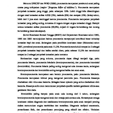
(Virtual Private Network) - A network that uses a public telecommunication Infrastructure, such as the Internet, to provide remote offices or individual users with secure access to the CPECC’s network. VPN’s use encryption and other Mechanisms to ensure that only authorized users can access the network and that the data cannot be intercepted. CPECC has connected VPN to CPECC sites at IRAQ and sub-contractors. 14.1 14.1.5
VPN Connection to Sub-contractors
Sub-contractor
Company
Cloud Internet
cu Site to Site Se
Company SSL VPN
Firewall
Firewall
red VPN
Company User CH2M SSL VPN
Firewall
MFP
A
CPECC Network
Sub-contractor
CPECC IRAQ Main Office
A Core Switch CPECC Network
14.1.6
Figure 1: VPN connection layout 14.1.8 14.1.97.1.4 Internet Line and point to point Express connection CPECC has 50 MBPS Dedicated Internet leased line for users and other devices, it will be managed 24 hours by the Internet service provider and it has 10MBPS 3G WI-FI Connectivity also if the physical goes down CPECC can get internet access from the 3G it will work automatically. CPECC has 10 MBPS point to point express connection Abu Dhabi to Dubai and China, CPECC group are connected in the Intranet. 14.1.107.1.5
Bluecoat Proxy
Manage the internet connection, to allocated Bandwidth limit for the user groups. To get report for users internet usages from this box. 14.1.117.1.6
Core Switch
To create Multiple VLANS, segregated the Network Structure, and edge switches Controlled by the CPECC core switch. 14.1.127.1.7
AVAYA IP Office and Telephone
CPECC
Category II, Rev. C Page 9 of 21
IQWQ-CE-BPIMP-00-0901
Project Information Management Plan
08-MAR-2015
CPECC has 450 individual telephone numbers, it has managed by the AVAYA IP office, Telephone provided to Company and sub-contractors. 14.1.137.1.8
POLYCOM
CPECC has3 Numbers Video Meeting Rooms, each room has Polycom Device with HD Camera and it Can able to connect up to 4 Sites, apart from the Polycom device CPECC deployed POLYCOM MCU from this MCU capable to connect up to 16 Sites at a time. 14.1.147.1.9
Servers
Centralized Domain controller to control all CPECC sites, Backup domain controller in case domain controller goes down, the backup domain controller will be effect, Symantec backup server controlling data backup as per the backup projects, FTP server to share data to sub-contractors and clients. WSUS for Microsoft windows server update service to update new patch to all servers. 14.1.157.1.10
Storage
CPECC share data to company and sub-contractors, Storages Located in CPECC IRAQ Main office (Abu Dhabi), one is for main Document Share, another is for Backup and three(3)storages located in project sites in IRAQ. It’s with DATA Replication in Main office. The layout of storage is depicted in the diagram as illustrated below;
Figure 2: Storages layout 14.1.167.1.11
File Transfer Protocol (FTP)
Files may be transferred to secure FTP sites through the use of appropriate security precautions. Requests for any FTP transfers should be directed to the Privacy Officer or appropriate personnel..
CPECC
Category II, Rev. C Page 10 of 21
IQWQ-CE-BPIMP-00-0901
Project Information Management Plan
08-MAR-2015
14.1 CCTV Security 14.1.18 Fourteen(14) no’s of close circuit television cameras installed at our premises to monitor employee, contractor, sub-contractors and visitors, this is for only security purpose. 14.1.19 Door Access Security 14.1.20 Each door has security access control, each employee, contractors and sub-contractors have access card and thumb access also to open the door, it has been monitor by network administrator as per management instruction. 14.1.217.1.12 Hardware Security Protections user Level Virus Protection: Home users must never stop the update process for Virus Protection. Virus Protection software is installed on all Practice personal computers and is set to update the virus pattern on a daily basis. This update is critical to the security of all data, and must be allowed to complete. Lock Screens: No matter what location, always lock the screen before walking away from the workstation. The data on the screen may be protected by CPECC may contain confidential information. Be sure the automatic lock feature has been set to automatically turn on after 10 minutes of inactivity Backup and Disaster recovery system refers to IT Security plan
CPECC
Category II, Rev. C Page 11 of 21
IQWQ-CE-BPIMP-00-0901
Project Information Management Plan
08-MAR-2015
14.2 CPECC Document Share details 14.3 Share folder shall be used as the mechanism for transfer documents between parties; it will be used for COMPANY, EPC CONTRACTOR, Engineering SUBCONTRACTOR and other SUBCONTRACTOR who has involved in the project. 14.4 Share folder created in data storage server, it will be the project name or as per manager instruction, under the root folder separate libraries are created for each party. 14.5 The data transmission will be controlled by each party responsible person. 14.6 Structure of the Share Folder 14.7 A project folder is created in Share Folder Server called "WQ1-CTPM ". Under this project folder, separate document libraries are created for each party. 14.8 After access is granted to the Share Folder Structure, each Party sees only the document library which the party is authorized to operate, i.e. WQ1-CTPM folder can be seen by CPECC or other party that has authorization to send/receive to that party, etc. 14.9 Under each party’s document library, folders for outgoing (CPECC to EMIL) & incoming documents (EMIL to CPECC) are created for the transfer of documents between two parties. 14.10 Typical Folder Structure (Documents folder) 14.11 Access and use of share folder 14.12 Go to run and type the document share server IP. 14.13 14.14 Example: 14.15
14.16 14.17 14.18 Once provided the server IP click ok, you can get like below image 14.19
CPECC
Category II, Rev. C Page 12 of 21
IQWQ-CE-BPIMP-00-0901
Project Information Management Plan
08-MAR-2015
14.20 14.21 14.22 When prompted for the username and password, enter the information as provided by the CPECC IT and click "OK". 14.23 14.24 User Name: cpecciraq\Project user 14.25 Password: XXXXXXXXX 14.26
14.27 14.28 14.29 Procedure 14.30 Party (A) write/upload documents into the document library folder called "CPECC", i.e. outgoing document are uploaded in the "CPECC to EMIL" folder/ EMIL. 14.31 14.32 Party (B) intends to send documents to party (A), "EMIL to CPECC" folder/ EMIL. 14.337.2 Document Control & Management 14.33.17.2.1 Document Control CPECC
Category II, Rev. C Page 13 of 21
IQWQ-CE-BPIMP-00-0901
Project Information Management Plan
08-MAR-2015
The Document Control Procedure provides a clear and concise description for document classification, management & control activities, which will be carried out by CPECC for the PHASE II Crude Tankage, Pumps and Meters Project. CPECC Document Control Procedure has been developed as Document No. IQWQ-CE-BPDCC00-0901. The procedure is applicable to CPECC, and its vendors and sub-contractors and COMPANY, EMIL. The Master Document Register (MDR) or Supplier Master Document Registers (SMDR) are generated by CPECC or Vendors / Sub-Contractors respectively and issued for review to EMIL. On approval, the EDMS is populated and document control applied to documents with all defined attributes as per the approved MDR / SMDR. The documents are issued for information or review based on an approved Document Distribution Matrix in the EMIL hierarchy or within CPECC. EMIL shall have access to CPECC EDMS for read/review / approve documents and upload its own comments. CPECC is responsible for ensuring that all its vendors and sub-contractors are sufficiently made aware of the documentation requirements including EDMS requirements for the project. CPECC shall ensure that the requirements are followed by all its vendors and sub-contractors. CPECC generates reports at regular intervals, report and take necessary action on receipt of documents, review status, completion and release and any delays caused in any of the stages. 14.33.27.2.2
TeambinderEDMS (Teambinder)
To meet the requirements of Phase II Crude Tankage, Pumps & Meters, CPECC Document Management System made up of project all Technical and Non-Technical documents. The TeamBinder (EDMS) will be maintained until the Phase II Crude Tankage, Pumps & Meters project is complete. CPECC will use TeamBinder as EDMS tool to support document production and control. TeamBinder (EDMS) system will be used to electronically store, share and distribute all project documents. This will enable Phase II Crude Tankage, Pumps & Meters Project to generate electronic documents to be electronically distributed, reviewed, approved and managed. All project documentation stored in EDMS including, design deliverables, supplier documentation and correspondence. It also allows to Company Project member to view project documents from the World Wide by Webpage: www.cpedms.com. Security access controls and document check-out / check-in functionality allow distributed teams to work and collaborate on a common set of documents. The detailed Information defined in the Document Control Procedure. Refer theIQWQ-CE-BPDCC00-0901 for Document Control Procedure. TeamBinder is a web-based project document management and collaboration system used to manage, store, and distribute information in the form of controlled documents and communications. Details refer to TeamBinder Operation manual.
CPECC
Category II, Rev. C Page 14 of 21
IQWQ-CE-BPIMP-00-0901
Project Information Management Plan
08-MAR-2015
14.33 In particular, TeamBinder will help you to manage: 14.33.4 The distribution, review and approval of documents during the project design phase. 14.33.5 The preparation, release for tender and award of sub contract document packages during the procurementphase. 14.33.6 Document distribution to COMPANY userbase on Document Distribution Matrix. 14.33.7 Document distribution to subcontractors during the construction phase. 14.33.8 All forms of communications between participants throughout the lifecycle of the project. 14.33.9 Document archiving at project completion and handover to the customer. 14.33.10 With all your project documents and communications managed and maintained on a secure, open platform,project participants are able to focus on the successful delivery of the project on time. 14.33.11 Once you have your login details you are ready to access TeamBinder. 14.33.12 Open Internet Explorer. 14.33.13 In the Address Line type www.cpedms.com. 14.33.14 Once the TeamBinder homepage has loaded, click the Login menu option. 14.33.15 At the login window, type your Username, your Company ID, and Password and click Login. 14.33.16 Tip: Tick the box “Remember Login User ID & Company” at the login window so that on the next login you 14.33.17 only need to enter your password. 14.33.18 If you have access to more than one project, click on the Project that you wish to login to. 14.33.19 The TeamBinder Dashboard will now load. 14.33.20 Notes:If you forget your password, click on the “Forgot your password?” link at the Login page and a new temporarypassword will be sent to you by email. Otherwise, please contact your Document Controller get a reset password from EPC CONTRACTOR EDMS Administrator. 14.33.21 Reviewers receive an email notification advising them of the documents they need to review plus a required by date.Click the Download icon to download the document to a PC for eitherprinting or offline review. 14.33.22 Example:
14.33.23 14.33.24 More information is available online (for all users)when login the TeamBinder – “Help” function on the right top as screen shot below:
14.33.25 14.33.26 14.33.27 14.33.28
TeamBinder Online Help
CPECC
Category II, Rev. C Page 15 of 21
IQWQ-CE-BPIMP-00-0901
Project Information Management Plan
08-MAR-2015
14.33.29 14.33.30 14.33.31 Model Environment 14.33.32 CPECC/CH2M HILL is using the following Project Data to be delivered to COMPANY at final handover: 14.33.33 3D Model; 14.33.34 2D CAD Drawings; 14.33.35 SPI Instrumentation Database; 14.33.36 EDMS Database. 14.33.37 Engineering Systems/IM Tools 14.33.387.2.3 AutoCAD CPECC/CH2M HILL will use AutoCAD for P&IDs drawings and 2D CAD drawings that will prepare for the project. CPECC shall refer to company specification documents IQWQ-FT-BSPDS-00010103 Upstream CAD Requirements – Drawings, Data and System to meet Company Requirements. All Drawings produced for this Project shall be prepared in AutoCAD 2013 format. However, as required by COMPANY, all drawings shall be saved into a lower version (2012) by changing AutoCAD settings. 14.33.397.2.4
Drawing Numbering
For drawing numbering assignments, refer to COMPANY Upstream Numbering System for Project Technical Documents (Doc. No.IQWQ-EI-BSPDS-00-120101). 14.33.407.2.5
File Naming Conventions
The CAD File Name shall be in accordance with COMPANY Upstream Numbering System for Project Technical Documents. The CAD file names are derived from the COMPANY drawing number and shall be assigned as per the below sample: Drawing Number: IQWQ-FT-PDPID-00-0633-001 Current Revision: A CAD File Name: IQWQ-FT-PDPID-00-0633-001_A.dwg. The detail Information refers the IQWQ-CE-BHCAD-00-0001 for CAD PROCEDURE MANUAL.
CPECC
Category II, Rev. C Page 16 of 21
IQWQ-CE-BPIMP-00-0901
Project Information Management Plan
08-MAR-2015
14.0 PDS Execution Procedure 14.35 The ENGINEERING SUB-CONTRACTOR shall use PDS 3D for the execution of the 3D Modeling activities. Refer to Attachment A for Software Versions to be used. 14.36 The ENGINEERING SUB-CONTRACTOR shall setup the PDS Database in its Home office in Abu Dhabi, U.A.E. This shall be configured in a Stand-alone Workshare environment to enable work to be distributed between AUH & INH offices. RIS dump of all schemas and file structure back up are to be given to COMPANY during final hand-over that can be restored to Oracle at completion. 14.37 Refer to Attachment C for the Illustration of Workshare for PDS. 14.38 3D Model Review 14.39 The PDS Administrator shall administer the 3D Model review session with the IPMT at agreed cycles (30, 60 and 90%). Microsoft Netmeeting or other software preferred by COMPANY shall be used as the medium for connecting participants during the 3D Model review sessions. 14.40 2D CAD Execution Procedure 14.41 The ENGINEERING SUB-CONTRACTOR shall use AutoCAD 2013 for the generation of 2D CAD drawings, however, at hand-over of the Project, the Drawings generated shall be converted to Microstation V8 Format. Refer to Attachment A for Software Versions to be used. 14.42 ENGINEERING SUB-CONTRACTOR shall follow the guidelines in the 2D CAD Procedure - CC0000-00000-PE-PRO-0004 to develop non-intelligent 2D CAD symbology and discipline-based template files. ENGINEERING SUB-CONTRACTOR shall obtain COMPANY approval to add symbols to the basic templates or change other aspects of the drawing layout or format. 14.43 It is the responsibility of the ENGINEERING SUB-CONTRACTOR to ensure that all 2D CAD drawings, including those produced by SUB-CONTRACTORS, SUPPLIERS and ENGINEERING SUB-CONTRACTOR affiliates, meet COMPANY standards. 14.44 2D CAD Execution Procedure 14.45 The ENGINEER shall use AutoCAD 2013 for the generation of 2D CAD drawings, however, at hand-over of the Project, the Drawings generated shall be converted to Microstation V8 Format. Refer to Attachment A for Software Versions to be used.. 14.46 ENGINEERING SUB-CONTRACTOR shall follow the guidelines in the 2D CAD Procedure - CC0000-00000-PE-PRO-0004 to develop non-intelligent 2D CAD symbology and discipline-based template files. ENGINEERING SUB-CONTRACTOR shall obtain COMPANY approval to add symbols to the basic templates or change other aspects of the drawing layout or format. 14.47 It is the responsibility of the ENGINEERING SUB-CONTRACTOR to ensure that all 2D CAD drawings, including those produced by SUB-CONTRACTORS, SUPPLIERS and ENGINEERING SUB-CONTRACTOR affiliates, meet COMPANY standards. 14.48 SPI Execution Procedure 14.49 The ENGINEERING SUB-CONTRACTOR shall use Smartplant Instrumentation for the generation of instrumentation deliverables in FEED stage as per Company Specification for the development of the instrumentation database (Doc.No.CC000-IC-SPC-0042) Attachment-A. Refer to Attachment A for Software Versions to be used. 14.50 The ENGINEERING SUB-CONTRACTOR shall setup the SPI Database in SQL 2008 in Denver Office wherein the Citrix server farm resides. The ENGINEERING SUB-CONTRACTOR shall setup the internal Workshare environment over Citrix, this configuration shall enable live database link within other ENGINEERING SUB-CONTRACTOR’s offices worldwide (AUH, INH & others). A complete SPI DB backup shall be given to the COMPANY during final handover that can be restored to Oracle at completion. 14.51 The data transfer scope and format between SPI and the Control Systems Vendor will be defined and Agreed between ENGINEERING SUB-CONTRACTOR and Integrated Control Systems vendor in the FEED stage. 14.52 See Attachment D for the Illustration of Workshare for SPI. 14.53 EDMS Execution Procedure 14.54 The ENGINEERING SUB-CONTRACTOR shall implement an electronic document management system (EDMS) called WRENCH. Refer to Attachment A for Software Versions. WRENCH is application wherein all engineering deliverables and their history and relevant correspondences are stored. 14.55 This software automatically enforces document management protocols and effectively monitors the process from creating the Work Breakdown Structure to compilation and handover of the documents. 14.56 It also helps process automation (workflow), project monitoring (deliverables & schedule), and document management (drawings, documents, activities & correspondences). 14.57 The system also defines deliverables and tasks and assigns them to each resource with time lines and resources to be notified to generate earned value based reports from the real-time status information to help monitor the project deliverables. CPECC
Category II, Rev. C Page 17 of 21
IQWQ-CE-BPIMP-00-0901
Project Information Management Plan
08-MAR-2015
14.58 The ENGINEERING SUB-CONTRACTOR shall setup the EDMS at its Home office in Abu Dhabi, U.A.E. wherein access to the Project Team members from different design offices shall be granted. 14.59 The ENGINEERING SUB-CONTRACTOR’s Home office shall be responsible for transmitting the deliverables required for review/approval process. The documents are transmitted to the EPC CONTRACTOR via TeamBinder, if in case of large file, it is copied to the CPECC’s Share Folder. 14.607.3 Design Software For list of Design Software to be used for the Project, refer to Attachment A. 15.08.0 TEMPLATE AND FORM Document Templates and forms refer to Document Control Procedure (Document No.IQWQ-CE-BPDCC00-0901) and Project Communication Plan (Document No.IQWQ-CE-BPCOM-00-0901). 16.09.0 PROJECT FINAL DOCUMENTATION (DFO) EPC DFO Coordinator shall develop Project Documents for Operations Plan to cover requirements set out in COMPANY DFO Specification PDS 210102 16.0
Documentation arises from all phases of the project from detail design (engineering) through to commissioning and operations. It is generated both by CPECC and its Subcontractors and Vendors. However, CPECC has ultimate responsibility for the handover of Final Documentation in accordance with this procedure. The overall Table of Contents given in Appendix A has been developed to capture the Final Documentation requirements for the project lifecycle and is grouped into nine basic categories as per the table below. 16.2 The document indexes will be created in accordance with the guidelines provided in the Document No. IQWQ-EI-BSPDS-00-210102 Rev.1Upstream Project Technical Documentation Requirements and Deliverablesand associated appendices. CPECC shall follow the applicable sections of the stated procedure to create, modify, maintain, organize, and handover documents and data in related packages as part of the EPC contractual requirements. A detailed Project Technical Documentation Deliverables Index shall be created and issued by CPECC as contract requirement, the exact Final Documentation packages to be handed over to EMIL. 9.1 For each package, there will be a separate index as defined in IQWQ-EI-BSPDS-00-210102 Rev.1 and associated appendicesDFO Handover to COMPANY EPC DFO will work with COMPANY Information Management Lead to determine the list of Contractor / 3rd Party documents and formats to be handed over to COMPANY in accordance with Project DFO Specification PDS 210102. The Project DFO Specification, PDS 21-01-02 details how the EPC, Vendors and Suppliers shall provide Documents for Operations to COMPANY per agreed Early and Final Deliverable Milestones. The DFO Specification identifies the documentation, defines the minimum requirements in both electronic and hard copy from the EPC, Suppliers and Vendors to be provided in the various DFO Categories listed below: The categories are: FD1 FD2 FD3 FD4 FD5 FD6 FD7 FD8 FD9
Section Type Code
Document Type Description
StartUp Critica l
The System Description Manual Operating and Maintenance Manuals Fabrication Records Book (FRB) Mechanical Catalogs and Manufacturing Record Book Systems Completion Dossiers Design Documentation Engineering Database Registers and Indexes Design Fabrication Installation (DFI) Résumé DFO Index
Electronic Format
No. Of Paper Copies
Editable Format Reqd.
AsBuilt Reqd.
CPECC
Ops. Critical Doc.
Final Delivery Milestone
Remarks
Category II, Rev. C Page 18 of 21
IQWQ-CE-BPIMP-00-0901
FD1
Systems Description
Y
MS-Word
2
Y
Y
Y
2 months before the first System Startup. Revisions are required for As-Built conditions.
Operating Procedures
Y
MS-Word, PDF, MS-Excel
5
Y
Y
Y
Facility Turnover Notice
N
MS-Word, PDF, MS-Excel
5
Y
Y
Y
Facility Turnover Notice
Y
Word, 3DCAD, Animation s, etc.
5
Y
Y
Y
Facility Turnover Notice
Maintenance Procedures
FD2
Project Information Management Plan
Training Manuals
IMR Subsea Documentati on (Inspection / Maintenance / Repair) Marine Operating Procedures
Operating Procedures per Appendix of this procedure Maintenance Procedures in accordance with Maintenance Procedure Requirements. Refer to Appendix for template. Training Manual to include Training Program and associated 3D-CAD model aides/animations and to conform to Operations Training and Competancy Evaluation Requirements.
Not Applicable for this project
Isometric Drawings
N
.dwg
2
Y
Y (Redlin e Marku ps Only)
Fabrication Record Books
N
MS-Word, PDF
0
N
Y
N
MC Complete (All Systems)
Mechanical Catalog
Y
MS-Word, PDF
3
N
Y
Y
MC Complete
MRB Manufacturin g Record Book
N
PDF
0
N
Y
N
At MC
Y
PDF
2
N
Y
Y
At MC
MRB Manufacturin g Record Book for Lifting Equipment Manufacturin g Record Book for Subsea and TieBack
System description includes: high level system summary, functional description, operations and control data, process and emergency shutdown, operations in emergency mode, equipment data safety procedures, StartUp and/or Shutdown, Maintenance, etc. Systems boundary definition and drawings (As-Built and BackDrafted)
Not Applicable for this project
FD3
FD4
08-MAR-2015
Y
MC Complete
All piping shall be documented on fabrication ISOs and updated in the 3D model. Also include stress ISOs, HVAC, Heat Tracing, Fire Water System isometrics. All weld traceability shall be shown. Scope of redlines per project specifications. Hard copy Fabrication Record Books to be maintained by CPECC for the life of the installation. Electronic version to be submitted to EMIL. Design Data and Operating Data. Vendor Package / Skid / Equipment User Manual Information. Refer to Appendix for requirements. A hard-copy of MRBs shall be retained by CPECC for the lifetime of installation. Electronic version to be supplied to Company. MRB shall document how the equipment was built, the standard to which it was built and shall provide evidence of the integrity and traceability of materials and workmanship.
Not Applicable for this project
CPECC
Category II, Rev. C Page 19 of 21
IQWQ-CE-BPIMP-00-0901
Project Information Management Plan
08-MAR-2015
Systems
Unpriced Copy of Each Purchase Order
N
PDF
1
NA
Y
NA
2 Weeks After PO is placed Final : MC Complete
Spare Parts Books and/or Databases
Y
MS-Excel
3
Y
N
Y
Facility Turnover Notice
All Export Control Documentary Evidence
N
PDF
2
N
N
N
Facility Turnover Notice
PSV Certificates
Y
Index : Excel Cert : PDF
2
N
Y
Y
Earlier than MC Comletion per System
Turnover and Completion Packages (TCP)
Y
MS-Word, PDF, MS-Excel
2
Y
Y
Y
Facility Turnover Notice
Installation, Survey and Positioning Data Reports
N
MS-Word, PDF, MS-Excel
2
N
Y
N
Lifting Equipment Certification
Y
Index : Excel Cert : PDF
2
Y/N
Y
Y
Videos and Photos of Submerged Structures
4 Weeks after completion of installation and/or survey activities Earlier than MC Completion per System
Two years operational, capital spares and/or insurance consumable spare. SPIRs and commissioning spares. Key export control related documents. See Appendix for detailed checklist of documents and ECCN item list format. PSV, Type Approval, Calibration, Pressure Test, PSV Index and Original Certificates Roll up of MC Status, Commissioning, and As-Built Status. See Appendix for the required
Lifting Equipment Certificates, Index, Originals plus Control Cards
Not Applicable for this project
FD5
MIR Documents: Design Assumptions, Material Selection, Welding Procedures, Recommended Repair Procedures, Corrosion Control and Monitoring features as designated and built into the facility.
Material Integrity Reports (MIR)
N
MS-Word, PDF
2
Y
Y
Y
Facility Turnover Notice
Index and Copies of Deviations
N
Index : Excel Copies : PDF
2
N
Y
N
MC Complete
N
Index : Excel Copies : PDF
2
Y
N
N
Facility Turnover Notice
Y
Facility Turnover Notice
As certified and approved by 3rd party verification contractor plus index with cross reference to relevant documents.
Facility Turnover Notice
All Design Documents from Contractor's Design Records (Master Document Register) showing As-Built Status. Engineering Design Books Includes: Design Basis, Philosophies, Specifications, Data-Sheets, Drawings, System Diagrams, CAD Model, Calculations, Analysis, Studies and Design Databases. (see note 1)
Index and Copies of NonConformance s Third Party Verification Index and Certificates
FD6
All unpriced purchase orders issued by CPECC, subcontractors and suppliers.
Complete Engineering Design Books as per approved Project Master Document Register and minimum requirements shown in Appendix.
N
See Appen dix
PDF
See Appendix
2
2
N
Y
N
Y(1)
CPECC
Y(1)
Category II, Rev. C Page 20 of 21
IQWQ-CE-BPIMP-00-0901
Project Information Management Plan
08-MAR-2015
Also see Note (1)
Subsea Free Span Calculations Engineering Documents and Supplier Documents Attribute Index
Not Applicable for this project
Y
MS-Excel
2
Y
Y
N
Project Acceptance Notice (AN)
Engineering Indexes
Y
MS-Excel or MSAccess
2
Y
Y
Y
Facility Turnover Notice
CMMS Database
Y
MSAccess
2
Y
Y
Y
Facility Turnover Notice
N
INtools® Database
2
Y
Y
As-Built at Facility Turnover Notice
ESRI ArcGIS Database for Geospatial Data
N
ArcGIS, ArcInfo and related Geodatabases
-
Y
Y
Project Acceptance Notice (AN)
FD8
DFI Resumes
N
MS-Word, PDF
2
Y
Y
Project Acceptance Notice (AN)
FD9
Documents for Operations Index
N
MS-Excel
2
Y
Y
FD7
INtools® Database SmartPlant Instrumentati on® (SPI)
IQWQ-EI-BSPDS-00-120101 and Appendix. Index must be supplied with Document Delivery. (This will include documents for all FD Categories) Engineering Registers, Indexes and Listings containing Engineering Data related to both Tag and Non-Tag components. These tables must be delivered in the specified format and with the required level of completion at the required milestones. Additional Registers and Indexes include: Anode Register, Lube Index, Relay Setting Index, Tie-in, and/or Hot-tap Register. Completed Company-provided Access database for population of data into SAPPM/MM Complete INtools® Database files. Watcom exported format or Oracle 9.1. Note: CPECC/CH2M shall utilize its own INtools® license for work performed but will hand over database files to EMIL. All Loops and Termination Drawings and Instrument Data Sheet deliverables are to be extracted from INtools® for handover in addition to the INtools® database. The INtools® database will be considered the primary or master repository while extracted files will be considered secondary copies. Data Model and Attribute requirements based upon the Pipeline Open Data Standard (PODS) or the preferred ArcGIS Pipeline Data Model (APDM). All co-ordinate data must be geo-referenced. General description of phases, installation, and heavily loaded area (e.g., pipeline and load bearing structures). Index for all FD Classes (1-8)
Note (1) : Some documents included in this FD6 category are Operations Critical and some are required As-Built (See Appendix for further definition)
CPECC
Category II, Rev. C Page 21 of 21
IQWQ-CE-BPIMP-00-0901
Project Information Management Plan
08-MAR-2015
ATTACHMENT – A DESIGN SOFTWARE LIST / VERSIONS ADD Attachment for MDR/SMDR
CPECC
Att- A (4 Pages)
Category II, Rev. B
IQWQ-CE-BPIMP-00-0901 ISCIPLINES
Software Name
All Disciplines
TeamBinder
Project Information Management Plan
AutoCAD Microstation
EPC CONTRACTOR Electronic Document Management System Engineering Document Management System CAD Software for 2D Deliverables 3rd Party CAD Software for PDS
Smartplant Review
3D Visualization
SQL
Database
Windows 7 Enterprise Windows Server Standard
Operating System (Client Machine), 32 or 64 bit
WRENCH
MS Office Civil & Structural
FrameWorks Plus Foundation 3D Mat 3D STAAD Pro MathCAD
Electrical
ETAP
Chalmlite
Power system design and analysis including arc flash, load flow, short circuit, relay coordination, cable ampacity, transient stability, optimal power flow, etc.
2013 J 7.1 (PDS only) 2012 (V09.00.00.0343) 2005 (PDS) & 2008 (SPI) Windows 7 Enterprise SP1 Windows Server SP2 2007 11.0 6.0.2 6.0.2 V8I (20.07.08.22) 15.0
12.0
2009.3 SP3 HF2
Infomaker Citrix Metaframe
V11.5 XenApp6
Compress
Pressure Vessels/Towers design software
6.3
PV Elite
Pressure Vessels/Towers design software
2011
HTRI
software to design heat exchangers and rate or simulate the performance of heat exchangers.
6.0
E20-II
HVAC Load/Energy Calculations; E20-II includes HAP (Hourly Analysis Program), System Design Loads, Block Load & Engineering Economic Analysis
4.5
Orthogen Caesar II
Extract 2D Drawings from the Model Stress Analysis Software
7.4.6 5.30 (2011)
PDS 3D
3D Plant Design
2010 (11.00.00.08)
OLGA PIPESIM
Dynamic Simulation Hydraulic Simulation software
6.3 2009
Smartplant Instrumentation
CPECC
Foundation design using rigid plate assumption Structural Analysis & Design Calculations
3.11.3.0
Instrumentation Design
Instrumentation & Control
Piping, Electrical, I&C & Civil/Structural Process
Used Administrative and Technical Document generation 3D Structural Modeling Spread and combined footing analysis/design tool that completes soil or pile supported foundation
Latest
4.05
PHA-Pro
Piping
Operating System (Server)
Version
Lighting design software program Log of HAZOP Action Items and Report Generation
HSE
Mechanical
Software Description / Function
08-MAR-2015
Att- A (1 of 3)
8.0
Category II, Rev. C
IQWQ-CE-BPIMP-00-0901 ISCIPLINES
Project Information Management Plan
Software Name
Software Description / Function
Version
Predict
Prediction of Corrosion of Steel for Oil/Gas Production/Transmission of Applications
6.0
ProMax
Used for amine system and Glycol Dehydration units process simulation. This software is an industry standard in Alberta.
3.2
PSVPlus Aspen Plus Fathom
7.0 (2012.01)
6.7
Risk & Decision Management Software
5.5
Risk Management Software
8.7
Microsoft Excel
Schedules and Reports
2007
AutoTurn
Vehicle Swept Path Analysis
8.1.2
TransoftAutoTurn
6.1
Path Planner
5.0
Traffic Simulation
5.40
Planning and Scheduling
8.0
Highway Planning and Design (Roundabout Design) Traffic operations analysis software for highway capacity and simulation software Travel demand modeling software
4.0
TRANSYT
14
SATURN
11.1.10
AIMSUN
7.0
Autodesk Architectural Desktop
2010/2011
Adobe Creative suite Premium
CS2, CS5
V-Ray
NA
Innovyze – InfoWorks CS and WS
12.5
HEC RAS
4.1.0
Oracle Primavera P6 DecisionTools Suite Ind. Risk Analysis (Primavera Pertmaster)
Path Planner Dynamite-VSP VISUM/VISSIM SYNCHRO SIDRA HCS (Highway Capacity Software) EMME TRANSYTSATURN AIMSUN Autodesk Architectural Adobe Creative suite V-Ray
CPECC
8.0
Project Scheduling
Project Planning & Controls
Water, Drainage and Wastewater Treatment
7.0.3
6.1
FRED
Architecture and Urban Planning
Designing of Relief Valves HYSYS - Hydraulic Simulation / Flarenet Design, Rating & Debottlenecking of Flare & Vent System / HTFS - Heat Exchanger and Simulation & Design Incompressible Pipe Flow Modeling (Fire, Release, Explosion, Dispersion) is a software system which models the consequences of a release of product, both accidental and intentional.
Process Safety
Transportation
08-MAR-2015
Att- A (2 of 3)
2010 3.3
Category II, Rev. C
IQWQ-CE-BPIMP-00-0901 ISCIPLINES
Project Information Management Plan
Software Name
Software Description / Function
Version
HY8 Culvert Analysis
Culvert Design
7.0
MDCAD
11.4, 12.5
Windes
11.4, 12.5
Bentley WaterCAD
Water Supply and Distribution
V8i
Bentley WaterGEMS Bentley Flowmaster
Analytical tool for water design scenarios and steady state modelling Bentley Flowmaster
V8i
CM Waste Management Calculates uniform flow for various conveyances, i.e., pipes and open channels Staad Pro
V8i XM
StaadPro
V8I (20.07.08.22)
MultiRebar
2010
MDCAD Windes
CulvertMaster Staad Pro StaadPro MultiRebar MRoad Tedds
V8i
V8I (20.07.08.22)
MRoad
NA
Structural Steel Detailing
14
Prokon
2.5
Safe
12.3
Etabs
9.7
Sap 2000
14
MIDAS Civil
2012
Bentley RAM Structural
Structural analysis/design
V8i, release 14
Reward
Reward
2.5
Prokon Structural Safe Sap Etabs MIDAS
Marine (See Note 1) FLAC Survey
08-MAR-2015
Surfer
Two-dimensional explicit finite difference program for engineering mechanics computation. Contouring and surface maps
6.0
10.0
Note 1: Inputs to several technical reports & simulations will require proprietary software & systems which will be identified and described at a later date based on further assessment of inputs to modeling in particular for the following: Numerical modeling; Marine design –ports; Coastal design; Navigation simulations.
CPECC
Att- A (3 of 3)
Category II, Rev. C
IQWQ-CE-BPIMP-00-0901
Project Information Management Plan
08-MAR-2015
ATTACHMENT – B DADD MDR/SMDR ATTRIBUTES OCUMENTS PRODUCED FROM DESIGN SOFTWARE TOOLS
Document Type
Design Tool
Orig Doc Size
Equipment Datasheet
MS Excel (with embedded graphics)
A4
Process/Utility Flow Diagram
AutoCAD
A1
Instrument Index
SmartPlant Instrumentation
A3
Instrument Specification Sheet Instrument Loop Diagrams (ILDs)
SmartPlant Instrumentation SmartPlant Instrumentation
A4 A3
CPECC
Att-B (2 Pages)
Category II, Rev. C
IQWQ-CE-BPIMP-00-0901
Project Information Management Plan
08-MAR-2015
Instrument Data Sheet
SmartPlant Instrumentation
A4
Cable Schedule
SmartPlant Instrumentation
A3
Instrumentation Junction Box Reports Calculation Sheet and Sizing
SmartPlant Instrumentation SmartPlant Instrumentation
A3 A4
Electrical Schematics
AutoCAD
A1
Single Line Diagrams Orthographic Drawings (Foundation and Piling Plans, Plot Plans, General Arrangements, Cable Tray Layouts and Reports, Electrical Terminations and Layouts, Mechanical Layouts, Architectural Building Layouts, Site Layouts, etc.) All other 2D CAD Drawings (except P&IDs)
AutoCAD
A1
AutoCAD
A1
AutoCAD
A1
CPECC
Att-B (2 Pages)
Category II, Rev. C
IQWQ-CE-BPIMP-00-0901
Project Information Management Plan
0830-NOVMAR-20145
ATTACHMENT – C WORKSHARE CONFIGURATION (PDS) Each entry in the MDR/SMDR will contain the following metadata: 1) Document number 2) Document title 3) Electronic file name 4) Integrity critical documentation 5) Revision code 6) Revision description 7) Planned, forecast, and actual dates for each issue 8) Document review category. (I, II, III, IV) 9) As-Built Requirements (Y/N) 10) As-Built Date 11) Interface identification 12) Status of Company review. (A,B,C,D) 13) Document disposition coding (for retention) 14) The hard copy size 15) The software format of electronic documents 16) Document included in the Bid Packages (Y/N) 17) Holds (Y/N) 18) 3rd party verification/regulatory submission (Y/N) 19) Country Code 20) Facility/ Plant Code 21) Document Originator Code 22) Area/ Unit / Location Code
CPECC
Category II, Rev. CB Page 1 of 2
IQWQ-CE-BPIMP-00-0901
Project Information Management Plan
0830-NOVMAR-20145
23) Discipline Code 24) Doc Type 25) System No. 26) Doc Sub Type 27) Sequential No. 28) Sheet No. 29) P.O. Contract No. 30) Tag No. V.P. Tag No.
CPECC
Category II, Rev. CB Page 2 of 2
IQWQ-CE-BPIMP-00-0901
Project Information Management Plan
0830-NOVMAR-20145
31) DFO ED / FD Category 32) DFO Book Volume No. 33) Start Up Critical (Y/N) 34) MPI Class 35) Media File Path 36) Language 37) SDR Code 38) Alternate Doc Reference Number
Worksharing SATELLITE SITE 1 MASTER SITE Final Hand-over Backup: RIS & Schema incl. plant structure
(ENGINEERING SUB-
CONTRACTOR -CH2) IN AUH data are All SettingsPDS andDB Reference (SQL) controlled from the master site
ENGINEERCH2 PDS DB in INH (S OTHER OFFICES ENGINEERCH2 Model File only in AES AUH – Abu Dhabi INH – New Delhi
CPECC
Category II, Rev. CB Page 2 of 2
IQWQ-CE-BPIMP-00-0901
Project Information Management Plan
CPECC
0830-NOVMAR-20145
Category II, Rev. CB Page 3 of 2
IQWQ-CE-BPIMP-00-0901
Project Information Management Plan
0830-NOVMAR-20145
ATTACHMENT – D CITRIX WORKSHARE
ENGINEER (AUH Users) Final Hand-over DB Backup – SPI
Connected (ENGINEER-CH2) SPI DB (SQL)
CPECC
Att-B (2 of 2)
ENGINEER (INH Users) AUH – Abu Dhabi INH – New Delhi
Category II, Rev. C
ENGINEER (Other Users)
IQWQ-CE-BPIMP-00-0901
CPECC
Project Information Management Plan
Att-B (3 of 2)
0830-NOVMAR-20145
Category II, Rev. C
WEST QURNA I SECTION 2
PHASE II CRUDE TANKAGE, PUMPS & METERS (127) PROJECT INFORMATION MANAGEMENT PLAN 00 - COMMON OVERALL - ALL AREAS IQWQ-CE-BPIMP-00-0901
Rev.
Date
Description
Prepared By
Verified By
Approved By
A
11-NOV-2014
Issued for Internal Review
J. Zhilan
Z. Xuewen
R. Gangfeng
B
30-NOV-2014
Issued for Review & Comments
J. Zhilan
Z. Xuewen
R. Gangfeng
C
08-FEB-2015
Issued for Review & Comments
R. Kurian
Z. Xuewen
R. Gangfeng
IQWQ-CE-BPIMP-00-0901
Project Information Management Plan
08-MAR-2015
TABLE OF CONTENTS 1.0 2.0 3.0
4.0 5.0
6.0 7.0
8.0 9.0
SCOPE ......................................................................................................................................................... 2 REFERENCES ............................................................................................................................................. 3 DEFINITION AND ABBREVIATION ............................................................................................................ 3 3.1 Definition ....................................................................................................................................... 3 3.2 Abbreviation .................................................................................................................................. 4 PROJECT IDENTIFICATION ....................................................................................................................... 4 ORGANIZATION AND RESPONSIBILITIES .............................................................................................. 4 5.1 Organization .................................................................................................................................. 4 5.2 Roles and Responsibilities ............................................................................................................ 5 5.2.1 Project Director (PD) ..................................................................................................................... 5 5.2.2 Document For Operation............................................................................................................... 5 5.2.3 Site Document Controller .............................................................................................................. 6 5.2.4 Project Engineer (PE) ................................................................................................................... 6 5.2.5 Administrative ................................................................................................................................ 6 5.2.6 Quality Management ..................................................................................................................... 6 5.2.7 Document Lead ............................................................................................................................. 5 5.2.8 IT Team (Network System Management) ..................................................................................... 7 5.2.9 IT Team (Communication System Management) ......................................................................... 7 5.2.10 EDMS Global Support Group ........................................................................................................ 7 INFORMATION MANAGEMENT PROCESS .............................................................................................. 7 6.1 Project Specific Numbering ........................................................................................................... 8 INFORMATION ENTERPRISE .................................................................................................................... 8 7.1 Information Systems & Security reference to IT Security Plan ..................................................... 8 7.1.1 Network Security ........................................................................................................................... 8 7.1.2 Virus Protection ............................................................................................................................. 8 7.1.3 VPN ............................................................................................................................................... 9 7.1.4 Internet Line and point to point Express connection ..................................................................... 9 7.1.5 Bluecoat Proxy .............................................................................................................................. 9 7.1.6 Core Switch ................................................................................................................................... 9 7.1.7 AVAYA IP Office and Telephone .................................................................................................. 9 7.1.8 POLYCOM .................................................................................................................................. 10 7.1.9 Servers ........................................................................................................................................ 10 7.1.10 Storage ........................................................................................................................................ 10 7.1.11 File Transfer Protocol (FTP) ....................................................................................................... 10 7.1.12 Hardware Security Protections user Level .................................................................................. 11 7.1.13 Backup and Disaster recovery system refers to IT Security plan ............................................... 11 7.2 Document Control & Management .............................................................................................. 13 7.2.1 Document Control ....................................................................................................................... 13 7.2.2 EDMS (Teambinder) ................................................................................................................... 14 7.2.3 AutoCAD ..................................................................................................................................... 16 7.2.4 Drawing Numbering .................................................................................................................... 16 7.2.5 File Naming Conventions ............................................................................................................ 16 7.3 Design Software .......................................................................................................................... 18 TEMPLATE AND FORM ............................................................................................................................ 18 PROJECT FINAL DOCUMENTATION (DFO) ........................................................................................... 18 9.1 DFO Handover to COMPANY ..................................................................................................... 18
ATTACHMENTS Attachment – A : DESIGN SOFTWARE LIST / VERSIONS Attachment – B : DOCUMENTS PRODUCED FROM DESIGN SOFTWARE TOOLS Attachment – C : WORKSHARE CONFIGURATION (PDS) Attachment – D : CITRIX WORKSHARE Attachment – E MDR/SMDR ATTRIBUTES
CPECC
Category II, Rev. C Page 1 of 21
IQWQ-CE-BPIMP-00-0901
1.0
Project Information Management Plan
08-MAR-2015
SCOPE Information Management and Document Control include document creation, control, management, and final handover to COMPANY. The Information Management Plan is developed to ensure that all phases of the project Engineering, Procurement, Construction, Commissioning activities meet the requirements specified by COMPANY. The procedure is applicable to all the described phases. This Information Management Plan rocedureis intended to be used by CPECC, the EPC Contractor, its Vendors and Sub-Contractors for activities associated with the creation, control, management and handover of documents, drawings and other project information related all phases of the PHASE II Crude Tankage, Pumps and Meters Project. The objective of this Information Management Plan is to outline the approach and strategies to develop and manage documents in a secure, cost-effective and timely manner. Specific objectives include: The procedure has the following major objectives: To establish and oversee the process of Document Control & Management including tracking, receiving, filing, storing, controlling, distributing, safeguarding and delivering of all project documents, such as drawings, certificates, reports and correspondence and other allied information generated during the execution of the project from the detailed engineering till the handover of the project.
2.0
To establish and oversee the process of Creating, Managing, Reporting and Delivery of Project Final Documentation in accordance with defined requirements of COMPANY, EMIL, thereby preventing delays in delivery of documentation.
Ensure that all documents and information generated in the project execution process are secure based on COMPANY’s related Document Specification Requirements.
Assure information is timely, accessible, and current.
Identifying deliverables and the appropriate attributes, classifications, categorizations, and electronic formats required by COMPANY.
Ensuring proper exchange of data and that only current, approved documents are used to perform work.
Adhering to project document numbering and equipment tagging requirements per approved project specifications.
Tracking evolving deliverables.
Minimizing turnaround between CPECC and COMPANY.
Standardization to ensure consistent formatting and delivery of information.
Enabling the smooth and timely transition of information to COMPANY.
Meeting Company security of information and records retention requirements.
Develop and Deliver Final DFO Deliverables to Company.
To establish and oversee the process of Document Control & Management including tracking, receiving, filing, storing, controlling, distributing, safeguarding and delivering of all project
CPECC
Category II, Rev. C Page 2 of 21
IQWQ-CE-BPIMP-00-0901
Project Information Management Plan
08-MAR-2015
documents, such as drawings, certificates, reports and correspondence and other allied information generated during the execution of the project from the detailed engineering till the handover of the project. 3.0 To establish and oversee the process of Creating, Managing, Reporting and Delivery of Project Final Documentation in accordance with defined proceduresof COMPANY, EMIL, thereby preventing delays in delivery of documentation. 4.0 Ensure that all documents and information generated in the project execution process are secure based on COMPANY’srelated Document Specification Requirements. 5.02.0 REFERENCES ADD DFO PLAN Doc number HOLD to be developed
IQWQ-FT-BSPDS-00-120115
:
Specification – Upstream Information Management Process
IQWQ-FT-BSPDS-00-010103
:
Upstream CAD Requirements – Drawings, Data and System
IQWQ-EI-BSPDS-00-120101
:
Upstream Numbering System for Technical Documents
IQWQ-EI-BSPDS-00-210102
:
Upstream Project Technical Documentation Requirements and Deliverables
IQWQ-CE-BPPPP-00-0901
:
Project Execution Plan
IQWQ-CE-QPQAC-00-0901
:
Project Quality Plan
IQWQ-CE-BPCTL-00-0901
:
Project Controls Plan
IQWQ-CE-BPCOM-00-0901
:
Project Communication Procedure
IQWQ-CE-BPDCC-00-0901
:
Document Control Procedure
IQWQ-CE-BLMDR-00-0001
:
Master Document Register / Supplier Master Document Register
IQWQ-CE-BSMAN-00-0001
:
PDS Procedures Manual
IQWQ-CE-BHCAD-00-0001
:
CAD Procedures Manual
IQWQ-CE-BBDFO-00-0901
:
DFO Management, Compilation and Handover Procedure
6.0 7.03.0 DEFINITION AND ABBREVIATION 7.13.1 Definition 3rd Parties
:
Sub Contractors, Suppliers and Vendors
COMPANY
:
ExxonMobil Iraq Ltd. (EMIL).
EPC CONTRACTOR
:
Refers to the Organization or Contracting Firm assigned by the COMPANY to perform the Engineering, Procurement & Construction (EPC) of the Contract and Works. The EPC CONTRACTOR refers to China Petroleum Engineering& Construction Corp. (CPECC).
Engineering SUBCONTRACTOR
:
Refers to the Organization or Contracting Firm assigned by the EPC CONTRACTOR to perform the Detailed Engineering of the Project. The Engineering SUBCONTRACTOR refers to CH2M HILL International B.V. Abu Dhabi.
SUBCONTRACTOR
:
A party subcontracted by EPC CONTRACTOR or Engineering SUBCONTRACTOR to perform a portion of the Services.
CPECC
Category II, Rev. C Page 3 of 21
IQWQ-CE-BPIMP-00-0901
Project Information Management Plan
VENDOR Shall Should
08-MAR-2015
: : :
Manufacturers / Suppliers of Goods and Equipment. Indicates a mandatory requirement. Indicates a strong recommendation to comply with the requirements of these documents/drawings.
CADD
:
Computer Aided Drafting and Design
DC
:
Document Control Lead
DDM
:
Document Distribution Matrix
DFO
:
Documents For Operations
MDR
:
Master Document Register
LAN
:
Local Area Network
SMDR
:
Supplier Master Document Register
EDMS (TeamBinder)
:
EPC CONTRACTOR’s Electronic Document Management System
EDMS (WRENCH)
:
Engineering SUBCONTRACTOR’s Electronic Document Management System
PDS
:
Plant Design System
PT
:
Project Team
RIS
:
Relational Interface System
SPI
:
SmartPlant Instrumentation
SPR
:
SmartPlant Review
WBS
:
Work Breakdown Structure
7.23.2 Abbreviation
8.04.0 PROJECT IDENTIFICATION The following information shall be used to identify the project for all correspondences and documents. Project Name
:
Phase II Crude Tankage, Pumps & Meters
Contract No.
:
W3QR-40-M127/W3QR-40-T127
CPECC Project No. :
M127/T127
9.05.0 ORGANIZATION and RESPONSIBILITIES 9.15.1 Organization The Information Management Team will be organized as shown below:
The information management team will be organized as shown:
CPECC
Category II, Rev. C Page 4 of 21
IQWQ-CE-BPIMP-00-0901
Project Information Management Plan
08-MAR-2015
9.25.2 Roles and Responsibilities The following individuals are available on the Project to assist in the project-specific coordination and support of the project information management requirementsworks. These individuals shall be responsible to maintain the following Project Data: 9.2.15.2.1 Project Director (PD)
The Project Director is responsible for overall Project execution and profitability. He serves as the principal point of contact with EPC CONTRACTOR for the Project. Ensures that an appropriate Project filing system is in place, by overseeing the document control processes and continuously liaising with Document Control Lead and DFO Coordinator. 9.2.25.2.2
DFO Coordinator
1.0
The DFO Coordinator OR Supervisor? reporting to the Project Director shall provide Information Management leadership and Training to Project members to meet COMPANY requirements in Information Management and Document Control. The DFO Coordinator and Document Control Lead shall work with COMPANY Information Management Lead on all aspects of Information Management, Document Control and Document For Operations COMPANY requirements. The Information Management Plan shall be developed and updated to cover the changing needs across the project phases. DFO Coordinator is responsible for;
Interface with COMPANY DFO Focal Point on DFO requirements Develops and Update Documents For Operations Plan across the various Project Phases Coordinate communications and efforts between the EPC and COMPANY to define Documents for Operations and how they will be developed and handed over to COMPANY. Ensure DFO Specification requirements are understood and met by EPC and Suppliers. Facilitate resolution of DFO queries and deviations. Monitor the PT review of DFO deliverables and turnover to COMPANY including status reporting. Transmit Early / Final DFO Deliverables to COMPANY. Shall work with COMPANY Information Management Lead on requirements to load deliverables into COMPANY EDMS
9.2.35.2.3 Document LeadAdd Document For Operations Role and activitiesAdd Site Document Control Role and activitieAdd Project Engineers Roles and activitieAdd Administrative Roles and actiAdd Quality Management Role and activitiAdd Project Director Role for meeting Information Management, Document Control and Document for Operations requirementsif Document Control Lead reports into PD The Document Control Lead is responsible to ensure that the Project Team, including the Document Controllers, adheres to this plan and related proceduresrocedure. The Document Control Lead is responsible for the following activities:
Shall Interface with COMPANY Information Management Lead on COMPANY Information Management, Document Control and Documents For Operations requirements.
CPECC
Category II, Rev. C Page 5 of 21
IQWQ-CE-BPIMP-00-0901
9.2.45.2.4
Project Information Management Plan
08-MAR-2015
Shall Comply with the requirements of COMPANY Coordination Procedure and referenced Specifications. Shall operate the EDMS for the Project and provides functional access to the COMPANY. Shall manage technical document flow process to and from Contractor and COMPANY and according to the COMPANY approved DDM. Shall Implement and maintain a Document Distribution Matrix based upon information provided by PT and the Master Document Register/ Supplier Master Document Register (MDR/ SMDR) with metadata as requested by COMPANY. Refer to Attachment B. Shall create and maintain the Project Master Library in Hard Copy and Electronic Formats as required. Shall be responsible for the issuing, distributing, and storing of weekly and monthly progress reporting, minutes of meetings, documents issued, late reporting, MDR/SMDR reports, DFO hand-over schedule, and any additional reports requested by COMPANY. Shall ensure latest documentation is controlled and readily available to the PT / COMPANY Shall update and ensure accuracy of the MDR and SMDRs for Vendors and Suppliers. Shall provide final handover documentation according to COMPANY DFO Specifications. Provides oversight of EPC Document Control through functional supervision of DCCs project wide;; Develops Project Information Management and related Proceduresdocument control and communication plans; Ensures Document Distribution Matrix (DDM) requirements are implemented; Coordinates with other parties and DCC Team to ensure smooth flow of documents; Implements roles and responsibilities as defined within EPC CONTRACTOR Document Control Procedure IQWQ-CE-BPDCC-00-0901. Site Document Controller
Site Document Controller is responsible for maintaining/managing distribution of hard and electronic copy of documents and drawings through TeamBinder and local server (share folder); which includes the technical and non-technical documentation at site. Site Document Controller will ensure that all technical and non-technical documents and drawings will be updated/maintained chronologically upto the satisfaction of COMPANY requirements as well as contractual agreement/obligation, as stipulated in contract documents, up to/during the project execution as well final handover of Documents For Operation (DFO). Site Document Controller to make sure that only the latest revision of documents/ drawings (CONTROLLED CCOPY) will be used at the work site (during the time of project execution phase). 9.2.55.2.5
Project Engineer (PE)
The Project Engineer (PE) assists the Project Manager in executing the overall Project. In particular, the Project Engineer is responsible for all engineering activities. The PE shall support the Project audit process by ensuring the availability of Project team members to respond in a timely and accurate manner to the requirements of the audit team. The PE shall also support the PD in responding to the findings of the audit report and implementing the recommended changes. The PE regularly establishes the status of the Project; handles EPC CONTRACTOR drawing requests and the exchange of data between disciplines; interfacing with procurement and subcontractors; expediting routing of Vendor documentation through engineering. 9.2.65.2.6
Administrative
Document Controller supports the Project by administering, filing and pulling Project deliverables, maintaining records of deliverables, making prints as required and generating transmittals. Also, the DC manages all project correspondences, i.e. letters, faxes memorandums, etc. 9.2.75.2.7
Quality Management
The QA/QC Engineer reports to PD on this specific project, however for general direction and CPECC
Category II, Rev. C Page 6 of 21
IQWQ-CE-BPIMP-00-0901
Project Information Management Plan
08-MAR-2015
reporting on quality activities, QA/QC Engineer reports to Quality Manager. The QA/QC Engineer is responsible for monitoring and measuring quality performance throughout the Project life cycle. The QA/QC Engineer is also responsible for the development and implementation of Project procedures and EQP, coordinating document control activities and responsible for auditing the Project quality system. Quality performance shall be measured through the use of the following activities: 9.2.85.2.8
Conducting audits; Assessing the Corrective Action & Preventive Action (CAPA) implementation; Assessing EPC CONTRACTOR satisfaction through Client Feedback Survey; Assisting in the preparation of Project Close-out Report. IT Team (Network System Management)
9.2.95.2.9
Organization, daily management and maintenance of LAN in project; Responsible for networking scheme and link design in project office locations; Responsible for maintenance and security of hardware equipment used for information management; Set up document sharing and delivering and routine maintenance of software/hardware; Dynamic monitoring of CPECC network data flow, scheme preparation, abnormal detection and alarm and emergency processing; Responsible for job related to network and communication management in CPECC QA/QC system; Completes the HSE management system and the relevant factors of network, communication management and control; Complete the identification, analysis and assessment of risk factors in network system, and take corrective and preventive actions. IT Team (Communication System Management)
9.2.105.2.10
Responsible for required analysis of audio communication system, function research of related products; Responsible for preparation, improvement and implementation of landline network scheme; Responsible for the site selection, formulation, link optimization and implementation of satellite communication system construction scheme; Responsible for installation, commissioning and operation of communication and video conference system; Responsible for analysis, control plan preparation and implementation of communication cost; Responsible for the connection and coordination of the audio communication system; Complete the identification, analysis and assessment of risk factors in communication system, and take corrective and preventive actions. EDMS Global Support Group
The TeamBinder (EDMS) will be set-up and configured in CPECC server in Dubai office. The TeamBinder Global Support will be QA Software technology group, it will responsible for Operation and Maintenance support till project end. 10.0 11.0
Document DatabaseAdministrator (EDMS-WRENCH) The EDMS Administrator is responsible for maintaining the document management system and ensures that appropriate access is given to the Project Team members. The EDMS Administrator is responsible for deleting/adding tasks in the EDMS as the design development evolves for the Project. 12.06.0 INFORMATION MANAGEMENT PROCESSDELIVERABLES All Technical Project Deliverables shall be numbered in accordance with Project Numbering s Specification CPECC
Category II, Rev. C Page 7 of 21
IQWQ-CE-BPIMP-00-0901
Project Information Management Plan
08-MAR-2015
and stored on the Project EDMS All Technical Project Deliverables shall be managed in accordance with Project Document Control Procedure All Non-Technical Documentation will numbered in accordance with Project Non-Technical Numbering requirements and managed in accordance with Project Non-Technical Document Control Procedure Project Communication Plan 12.1 Engineering Report 12.2 CPECC shall beresponsible to provide the following reports as per Company requirement: 12.3 Information Management Plan 12.4 Document Control Procedure 12.5 Project Communication Plan 12.6 MDR/SMDR Shall be submitted on a Monthly basis 12.7 Weekly Document status track reports shall be generated by CPECC EDMS (TeamBinder) 12.8 Technical Query Expediting Report shall be generated by CPECC EDMS (TeamBinder) 12.96.1 Project Specific Numbering CPECC shall follow the IQWQ-EI-BSPDS-00-120101 – Upstream Numbering System for Technical Documents. CPECC/CH2M HILL shall create and maintain a project document numbering procedure (IQWQ-CEBPDCC-00-0005), Internal Document Numbering Procedure. 13.0
Documents shall be numbered in accordance with Companyrequirements, detailed in IQWQ-EIBSPDS-00-120101. 14.07.0 INFORMATION ENTERPRISE CPECC IRAQ Information enterprise provides a technology platform that enables organization to integrate and coordinate major capital projects business process. CPECC Iraq Information enterprise ensures that information can be shared across all functional level and management hierarchies. All project documents are produced and controlled according to CPECC standards. CPECC will be using a common set of tools. Every issued document for which CPECC is responsible will reside in the EDMS and shall confirm to company and or project standards. To ensure data quality and consistency on the project, CPECC standard suite of office and applications are utilized on the project. Wherein it is required by Contract, COMPANY specified tools and methods are used. 14.17.1
Information Systems & Security reference to IT Security Plan
14.1.17.1.1
Network Security
Network attacks launched from the Internet or from CPECC networks can cause significant damage and harm to information resources including the unauthorized Disclosure of confidential information. In order to provide defensive measures against these attacks, firewall and network filtering technology must be used in a structured and consistent manner. CPECC maintains appropriate configuration standards and network security Controls to safeguard information resources from internal and external network mediated Threats. Fortigate Firewalls has deployed. 14.1.27.1.2
Virus Protection
Virus is a threat to the CPECC as infected computers may transmit confidential information to unauthorized third parties, provide a platform for unauthorized access or use of the internal network, contaminate or infect other network connected devices, or interfere with CPECC IT services. Antivirus software deployed to protect against the damage caused by virus attacks. Network administrators are responsible to ensure anti-virus software has the latest updates and virus signatures installed and also to verify that computers are virus-free. Manage the apps on desktop, prevent Trojan and virus which is from internet. CPECC
Category II, Rev. C Page 8 of 21
IQWQ-CE-BPIMP-00-0901
14.1.37.1.3
Project Information Management Plan
08-MAR-2015
VPN
(Virtual Private Network) - A network that uses a public telecommunication Infrastructure, such as the Internet, to provide remote offices or individual users with secure access to the CPECC’s network. VPN’s use encryption and other Mechanisms to ensure that only authorized users can access the network and that the data cannot be intercepted. CPECC has connected VPN to CPECC sites at IRAQ and sub-contractors. 14.1 14.1.5
VPN Connection to Sub-contractors
Sub-contractor
Company
Cloud Internet
cu Site to Site Se
Company SSL VPN
Firewall
Firewall
red VPN
Company User CH2M SSL VPN
Firewall
MFP
A
CPECC Network
Sub-contractor
CPECC IRAQ Main Office
A Core Switch CPECC Network
14.1.6
Figure 1: VPN connection layout 14.1.8 14.1.97.1.4 Internet Line and point to point Express connection CPECC has 50 MBPS Dedicated Internet leased line for users and other devices, it will be managed 24 hours by the Internet service provider and it has 10MBPS 3G WI-FI Connectivity also if the physical goes down CPECC can get internet access from the 3G it will work automatically. CPECC has 10 MBPS point to point express connection Abu Dhabi to Dubai and China, CPECC group are connected in the Intranet. 14.1.107.1.5
Bluecoat Proxy
Manage the internet connection, to allocated Bandwidth limit for the user groups. To get report for users internet usages from this box. 14.1.117.1.6
Core Switch
To create Multiple VLANS, segregated the Network Structure, and edge switches Controlled by the CPECC core switch. 14.1.127.1.7
AVAYA IP Office and Telephone
CPECC
Category II, Rev. C Page 9 of 21
IQWQ-CE-BPIMP-00-0901
Project Information Management Plan
08-MAR-2015
CPECC has 450 individual telephone numbers, it has managed by the AVAYA IP office, Telephone provided to Company and sub-contractors. 14.1.137.1.8
POLYCOM
CPECC has3 Numbers Video Meeting Rooms, each room has Polycom Device with HD Camera and it Can able to connect up to 4 Sites, apart from the Polycom device CPECC deployed POLYCOM MCU from this MCU capable to connect up to 16 Sites at a time. 14.1.147.1.9
Servers
Centralized Domain controller to control all CPECC sites, Backup domain controller in case domain controller goes down, the backup domain controller will be effect, Symantec backup server controlling data backup as per the backup projects, FTP server to share data to sub-contractors and clients. WSUS for Microsoft windows server update service to update new patch to all servers. 14.1.157.1.10
Storage
CPECC share data to company and sub-contractors, Storages Located in CPECC IRAQ Main office (Abu Dhabi), one is for main Document Share, another is for Backup and three(3)storages located in project sites in IRAQ. It’s with DATA Replication in Main office. The layout of storage is depicted in the diagram as illustrated below;
Figure 2: Storages layout 14.1.167.1.11
File Transfer Protocol (FTP)
Files may be transferred to secure FTP sites through the use of appropriate security precautions. Requests for any FTP transfers should be directed to the Privacy Officer or appropriate personnel..
CPECC
Category II, Rev. C Page 10 of 21
IQWQ-CE-BPIMP-00-0901
Project Information Management Plan
08-MAR-2015
14.1 CCTV Security 14.1.18 Fourteen(14) no’s of close circuit television cameras installed at our premises to monitor employee, contractor, sub-contractors and visitors, this is for only security purpose. 14.1.19 Door Access Security 14.1.20 Each door has security access control, each employee, contractors and sub-contractors have access card and thumb access also to open the door, it has been monitor by network administrator as per management instruction. 14.1.217.1.12 Hardware Security Protections user Level Virus Protection: Home users must never stop the update process for Virus Protection. Virus Protection software is installed on all Practice personal computers and is set to update the virus pattern on a daily basis. This update is critical to the security of all data, and must be allowed to complete. Lock Screens: No matter what location, always lock the screen before walking away from the workstation. The data on the screen may be protected by CPECC may contain confidential information. Be sure the automatic lock feature has been set to automatically turn on after 10 minutes of inactivity Backup and Disaster recovery system refers to IT Security plan
CPECC
Category II, Rev. C Page 11 of 21
IQWQ-CE-BPIMP-00-0901
Project Information Management Plan
08-MAR-2015
14.2 CPECC Document Share details 14.3 Share folder shall be used as the mechanism for transfer documents between parties; it will be used for COMPANY, EPC CONTRACTOR, Engineering SUBCONTRACTOR and other SUBCONTRACTOR who has involved in the project. 14.4 Share folder created in data storage server, it will be the project name or as per manager instruction, under the root folder separate libraries are created for each party. 14.5 The data transmission will be controlled by each party responsible person. 14.6 Structure of the Share Folder 14.7 A project folder is created in Share Folder Server called "WQ1-CTPM ". Under this project folder, separate document libraries are created for each party. 14.8 After access is granted to the Share Folder Structure, each Party sees only the document library which the party is authorized to operate, i.e. WQ1-CTPM folder can be seen by CPECC or other party that has authorization to send/receive to that party, etc. 14.9 Under each party’s document library, folders for outgoing (CPECC to EMIL) & incoming documents (EMIL to CPECC) are created for the transfer of documents between two parties. 14.10 Typical Folder Structure (Documents folder) 14.11 Access and use of share folder 14.12 Go to run and type the document share server IP. 14.13 14.14 Example: 14.15
14.16 14.17 14.18 Once provided the server IP click ok, you can get like below image 14.19
CPECC
Category II, Rev. C Page 12 of 21
IQWQ-CE-BPIMP-00-0901
Project Information Management Plan
08-MAR-2015
14.20 14.21 14.22 When prompted for the username and password, enter the information as provided by the CPECC IT and click "OK". 14.23 14.24 User Name: cpecciraq\Project user 14.25 Password: XXXXXXXXX 14.26
14.27 14.28 14.29 Procedure 14.30 Party (A) write/upload documents into the document library folder called "CPECC", i.e. outgoing document are uploaded in the "CPECC to EMIL" folder/ EMIL. 14.31 14.32 Party (B) intends to send documents to party (A), "EMIL to CPECC" folder/ EMIL. 14.337.2 Document Control & Management 14.33.17.2.1 Document Control CPECC
Category II, Rev. C Page 13 of 21
IQWQ-CE-BPIMP-00-0901
Project Information Management Plan
08-MAR-2015
The Document Control Procedure provides a clear and concise description for document classification, management & control activities, which will be carried out by CPECC for the PHASE II Crude Tankage, Pumps and Meters Project. CPECC Document Control Procedure has been developed as Document No. IQWQ-CE-BPDCC00-0901. The procedure is applicable to CPECC, and its vendors and sub-contractors and COMPANY, EMIL. The Master Document Register (MDR) or Supplier Master Document Registers (SMDR) are generated by CPECC or Vendors / Sub-Contractors respectively and issued for review to EMIL. On approval, the EDMS is populated and document control applied to documents with all defined attributes as per the approved MDR / SMDR. The documents are issued for information or review based on an approved Document Distribution Matrix in the EMIL hierarchy or within CPECC. EMIL shall have access to CPECC EDMS for read/review / approve documents and upload its own comments. CPECC is responsible for ensuring that all its vendors and sub-contractors are sufficiently made aware of the documentation requirements including EDMS requirements for the project. CPECC shall ensure that the requirements are followed by all its vendors and sub-contractors. CPECC generates reports at regular intervals, report and take necessary action on receipt of documents, review status, completion and release and any delays caused in any of the stages. 14.33.27.2.2
TeambinderEDMS (Teambinder)
To meet the requirements of Phase II Crude Tankage, Pumps & Meters, CPECC Document Management System made up of project all Technical and Non-Technical documents. The TeamBinder (EDMS) will be maintained until the Phase II Crude Tankage, Pumps & Meters project is complete. CPECC will use TeamBinder as EDMS tool to support document production and control. TeamBinder (EDMS) system will be used to electronically store, share and distribute all project documents. This will enable Phase II Crude Tankage, Pumps & Meters Project to generate electronic documents to be electronically distributed, reviewed, approved and managed. All project documentation stored in EDMS including, design deliverables, supplier documentation and correspondence. It also allows to Company Project member to view project documents from the World Wide by Webpage: www.cpedms.com. Security access controls and document check-out / check-in functionality allow distributed teams to work and collaborate on a common set of documents. The detailed Information defined in the Document Control Procedure. Refer theIQWQ-CE-BPDCC00-0901 for Document Control Procedure. TeamBinder is a web-based project document management and collaboration system used to manage, store, and distribute information in the form of controlled documents and communications. Details refer to TeamBinder Operation manual.
CPECC
Category II, Rev. C Page 14 of 21
IQWQ-CE-BPIMP-00-0901
Project Information Management Plan
08-MAR-2015
14.33 In particular, TeamBinder will help you to manage: 14.33.4 The distribution, review and approval of documents during the project design phase. 14.33.5 The preparation, release for tender and award of sub contract document packages during the procurementphase. 14.33.6 Document distribution to COMPANY userbase on Document Distribution Matrix. 14.33.7 Document distribution to subcontractors during the construction phase. 14.33.8 All forms of communications between participants throughout the lifecycle of the project. 14.33.9 Document archiving at project completion and handover to the customer. 14.33.10 With all your project documents and communications managed and maintained on a secure, open platform,project participants are able to focus on the successful delivery of the project on time. 14.33.11 Once you have your login details you are ready to access TeamBinder. 14.33.12 Open Internet Explorer. 14.33.13 In the Address Line type www.cpedms.com. 14.33.14 Once the TeamBinder homepage has loaded, click the Login menu option. 14.33.15 At the login window, type your Username, your Company ID, and Password and click Login. 14.33.16 Tip: Tick the box “Remember Login User ID & Company” at the login window so that on the next login you 14.33.17 only need to enter your password. 14.33.18 If you have access to more than one project, click on the Project that you wish to login to. 14.33.19 The TeamBinder Dashboard will now load. 14.33.20 Notes:If you forget your password, click on the “Forgot your password?” link at the Login page and a new temporarypassword will be sent to you by email. Otherwise, please contact your Document Controller get a reset password from EPC CONTRACTOR EDMS Administrator. 14.33.21 Reviewers receive an email notification advising them of the documents they need to review plus a required by date.Click the Download icon to download the document to a PC for eitherprinting or offline review. 14.33.22 Example:
14.33.23 14.33.24 More information is available online (for all users)when login the TeamBinder – “Help” function on the right top as screen shot below:
14.33.25 14.33.26 14.33.27 14.33.28
TeamBinder Online Help
CPECC
Category II, Rev. C Page 15 of 21
IQWQ-CE-BPIMP-00-0901
Project Information Management Plan
08-MAR-2015
14.33.29 14.33.30 14.33.31 Model Environment 14.33.32 CPECC/CH2M HILL is using the following Project Data to be delivered to COMPANY at final handover: 14.33.33 3D Model; 14.33.34 2D CAD Drawings; 14.33.35 SPI Instrumentation Database; 14.33.36 EDMS Database. 14.33.37 Engineering Systems/IM Tools 14.33.387.2.3 AutoCAD CPECC/CH2M HILL will use AutoCAD for P&IDs drawings and 2D CAD drawings that will prepare for the project. CPECC shall refer to company specification documents IQWQ-FT-BSPDS-00010103 Upstream CAD Requirements – Drawings, Data and System to meet Company Requirements. All Drawings produced for this Project shall be prepared in AutoCAD 2013 format. However, as required by COMPANY, all drawings shall be saved into a lower version (2012) by changing AutoCAD settings. 14.33.397.2.4
Drawing Numbering
For drawing numbering assignments, refer to COMPANY Upstream Numbering System for Project Technical Documents (Doc. No.IQWQ-EI-BSPDS-00-120101). 14.33.407.2.5
File Naming Conventions
The CAD File Name shall be in accordance with COMPANY Upstream Numbering System for Project Technical Documents. The CAD file names are derived from the COMPANY drawing number and shall be assigned as per the below sample: Drawing Number: IQWQ-FT-PDPID-00-0633-001 Current Revision: A CAD File Name: IQWQ-FT-PDPID-00-0633-001_A.dwg. The detail Information refers the IQWQ-CE-BHCAD-00-0001 for CAD PROCEDURE MANUAL.
CPECC
Category II, Rev. C Page 16 of 21
IQWQ-CE-BPIMP-00-0901
Project Information Management Plan
08-MAR-2015
14.0 PDS Execution Procedure 14.35 The ENGINEERING SUB-CONTRACTOR shall use PDS 3D for the execution of the 3D Modeling activities. Refer to Attachment A for Software Versions to be used. 14.36 The ENGINEERING SUB-CONTRACTOR shall setup the PDS Database in its Home office in Abu Dhabi, U.A.E. This shall be configured in a Stand-alone Workshare environment to enable work to be distributed between AUH & INH offices. RIS dump of all schemas and file structure back up are to be given to COMPANY during final hand-over that can be restored to Oracle at completion. 14.37 Refer to Attachment C for the Illustration of Workshare for PDS. 14.38 3D Model Review 14.39 The PDS Administrator shall administer the 3D Model review session with the IPMT at agreed cycles (30, 60 and 90%). Microsoft Netmeeting or other software preferred by COMPANY shall be used as the medium for connecting participants during the 3D Model review sessions. 14.40 2D CAD Execution Procedure 14.41 The ENGINEERING SUB-CONTRACTOR shall use AutoCAD 2013 for the generation of 2D CAD drawings, however, at hand-over of the Project, the Drawings generated shall be converted to Microstation V8 Format. Refer to Attachment A for Software Versions to be used. 14.42 ENGINEERING SUB-CONTRACTOR shall follow the guidelines in the 2D CAD Procedure - CC0000-00000-PE-PRO-0004 to develop non-intelligent 2D CAD symbology and discipline-based template files. ENGINEERING SUB-CONTRACTOR shall obtain COMPANY approval to add symbols to the basic templates or change other aspects of the drawing layout or format. 14.43 It is the responsibility of the ENGINEERING SUB-CONTRACTOR to ensure that all 2D CAD drawings, including those produced by SUB-CONTRACTORS, SUPPLIERS and ENGINEERING SUB-CONTRACTOR affiliates, meet COMPANY standards. 14.44 2D CAD Execution Procedure 14.45 The ENGINEER shall use AutoCAD 2013 for the generation of 2D CAD drawings, however, at hand-over of the Project, the Drawings generated shall be converted to Microstation V8 Format. Refer to Attachment A for Software Versions to be used.. 14.46 ENGINEERING SUB-CONTRACTOR shall follow the guidelines in the 2D CAD Procedure - CC0000-00000-PE-PRO-0004 to develop non-intelligent 2D CAD symbology and discipline-based template files. ENGINEERING SUB-CONTRACTOR shall obtain COMPANY approval to add symbols to the basic templates or change other aspects of the drawing layout or format. 14.47 It is the responsibility of the ENGINEERING SUB-CONTRACTOR to ensure that all 2D CAD drawings, including those produced by SUB-CONTRACTORS, SUPPLIERS and ENGINEERING SUB-CONTRACTOR affiliates, meet COMPANY standards. 14.48 SPI Execution Procedure 14.49 The ENGINEERING SUB-CONTRACTOR shall use Smartplant Instrumentation for the generation of instrumentation deliverables in FEED stage as per Company Specification for the development of the instrumentation database (Doc.No.CC000-IC-SPC-0042) Attachment-A. Refer to Attachment A for Software Versions to be used. 14.50 The ENGINEERING SUB-CONTRACTOR shall setup the SPI Database in SQL 2008 in Denver Office wherein the Citrix server farm resides. The ENGINEERING SUB-CONTRACTOR shall setup the internal Workshare environment over Citrix, this configuration shall enable live database link within other ENGINEERING SUB-CONTRACTOR’s offices worldwide (AUH, INH & others). A complete SPI DB backup shall be given to the COMPANY during final handover that can be restored to Oracle at completion. 14.51 The data transfer scope and format between SPI and the Control Systems Vendor will be defined and Agreed between ENGINEERING SUB-CONTRACTOR and Integrated Control Systems vendor in the FEED stage. 14.52 See Attachment D for the Illustration of Workshare for SPI. 14.53 EDMS Execution Procedure 14.54 The ENGINEERING SUB-CONTRACTOR shall implement an electronic document management system (EDMS) called WRENCH. Refer to Attachment A for Software Versions. WRENCH is application wherein all engineering deliverables and their history and relevant correspondences are stored. 14.55 This software automatically enforces document management protocols and effectively monitors the process from creating the Work Breakdown Structure to compilation and handover of the documents. 14.56 It also helps process automation (workflow), project monitoring (deliverables & schedule), and document management (drawings, documents, activities & correspondences). 14.57 The system also defines deliverables and tasks and assigns them to each resource with time lines and resources to be notified to generate earned value based reports from the real-time status information to help monitor the project deliverables. CPECC
Category II, Rev. C Page 17 of 21
IQWQ-CE-BPIMP-00-0901
Project Information Management Plan
08-MAR-2015
14.58 The ENGINEERING SUB-CONTRACTOR shall setup the EDMS at its Home office in Abu Dhabi, U.A.E. wherein access to the Project Team members from different design offices shall be granted. 14.59 The ENGINEERING SUB-CONTRACTOR’s Home office shall be responsible for transmitting the deliverables required for review/approval process. The documents are transmitted to the EPC CONTRACTOR via TeamBinder, if in case of large file, it is copied to the CPECC’s Share Folder. 14.607.3 Design Software For list of Design Software to be used for the Project, refer to Attachment A. 15.08.0 TEMPLATE AND FORM Document Templates and forms refer to Document Control Procedure (Document No.IQWQ-CE-BPDCC00-0901) and Project Communication Plan (Document No.IQWQ-CE-BPCOM-00-0901). 16.09.0 PROJECT FINAL DOCUMENTATION (DFO) EPC DFO Coordinator shall develop Project Documents for Operations Plan to cover requirements set out in COMPANY DFO Specification PDS 210102 16.0
Documentation arises from all phases of the project from detail design (engineering) through to commissioning and operations. It is generated both by CPECC and its Subcontractors and Vendors. However, CPECC has ultimate responsibility for the handover of Final Documentation in accordance with this procedure. The overall Table of Contents given in Appendix A has been developed to capture the Final Documentation requirements for the project lifecycle and is grouped into nine basic categories as per the table below. 16.2 The document indexes will be created in accordance with the guidelines provided in the Document No. IQWQ-EI-BSPDS-00-210102 Rev.1Upstream Project Technical Documentation Requirements and Deliverablesand associated appendices. CPECC shall follow the applicable sections of the stated procedure to create, modify, maintain, organize, and handover documents and data in related packages as part of the EPC contractual requirements. A detailed Project Technical Documentation Deliverables Index shall be created and issued by CPECC as contract requirement, the exact Final Documentation packages to be handed over to EMIL. 9.1 For each package, there will be a separate index as defined in IQWQ-EI-BSPDS-00-210102 Rev.1 and associated appendicesDFO Handover to COMPANY EPC DFO will work with COMPANY Information Management Lead to determine the list of Contractor / 3rd Party documents and formats to be handed over to COMPANY in accordance with Project DFO Specification PDS 210102. The Project DFO Specification, PDS 21-01-02 details how the EPC, Vendors and Suppliers shall provide Documents for Operations to COMPANY per agreed Early and Final Deliverable Milestones. The DFO Specification identifies the documentation, defines the minimum requirements in both electronic and hard copy from the EPC, Suppliers and Vendors to be provided in the various DFO Categories listed below: The categories are: FD1 FD2 FD3 FD4 FD5 FD6 FD7 FD8 FD9
Section Type Code
Document Type Description
StartUp Critica l
The System Description Manual Operating and Maintenance Manuals Fabrication Records Book (FRB) Mechanical Catalogs and Manufacturing Record Book Systems Completion Dossiers Design Documentation Engineering Database Registers and Indexes Design Fabrication Installation (DFI) Résumé DFO Index
Electronic Format
No. Of Paper Copies
Editable Format Reqd.
AsBuilt Reqd.
CPECC
Ops. Critical Doc.
Final Delivery Milestone
Remarks
Category II, Rev. C Page 18 of 21
IQWQ-CE-BPIMP-00-0901
FD1
Systems Description
Y
MS-Word
2
Y
Y
Y
2 months before the first System Startup. Revisions are required for As-Built conditions.
Operating Procedures
Y
MS-Word, PDF, MS-Excel
5
Y
Y
Y
Facility Turnover Notice
N
MS-Word, PDF, MS-Excel
5
Y
Y
Y
Facility Turnover Notice
Y
Word, 3DCAD, Animation s, etc.
5
Y
Y
Y
Facility Turnover Notice
Maintenance Procedures
FD2
Project Information Management Plan
Training Manuals
IMR Subsea Documentati on (Inspection / Maintenance / Repair) Marine Operating Procedures
Operating Procedures per Appendix of this procedure Maintenance Procedures in accordance with Maintenance Procedure Requirements. Refer to Appendix for template. Training Manual to include Training Program and associated 3D-CAD model aides/animations and to conform to Operations Training and Competancy Evaluation Requirements.
Not Applicable for this project
Isometric Drawings
N
.dwg
2
Y
Y (Redlin e Marku ps Only)
Fabrication Record Books
N
MS-Word, PDF
0
N
Y
N
MC Complete (All Systems)
Mechanical Catalog
Y
MS-Word, PDF
3
N
Y
Y
MC Complete
MRB Manufacturin g Record Book
N
0
N
Y
N
At MC
Y
2
N
Y
Y
At MC
MRB Manufacturin g Record Book for Lifting Equipment Manufacturin g Record Book for Subsea and TieBack
System description includes: high level system summary, functional description, operations and control data, process and emergency shutdown, operations in emergency mode, equipment data safety procedures, StartUp and/or Shutdown, Maintenance, etc. Systems boundary definition and drawings (As-Built and BackDrafted)
Not Applicable for this project
FD3
FD4
08-MAR-2015
Y
MC Complete
All piping shall be documented on fabrication ISOs and updated in the 3D model. Also include stress ISOs, HVAC, Heat Tracing, Fire Water System isometrics. All weld traceability shall be shown. Scope of redlines per project specifications. Hard copy Fabrication Record Books to be maintained by CPECC for the life of the installation. Electronic version to be submitted to EMIL. Design Data and Operating Data. Vendor Package / Skid / Equipment User Manual Information. Refer to Appendix for requirements. A hard-copy of MRBs shall be retained by CPECC for the lifetime of installation. Electronic version to be supplied to Company. MRB shall document how the equipment was built, the standard to which it was built and shall provide evidence of the integrity and traceability of materials and workmanship.
Not Applicable for this project
CPECC
Category II, Rev. C Page 19 of 21
IQWQ-CE-BPIMP-00-0901
Project Information Management Plan
08-MAR-2015
Systems
Unpriced Copy of Each Purchase Order
N
1
NA
Y
NA
2 Weeks After PO is placed Final : MC Complete
Spare Parts Books and/or Databases
Y
MS-Excel
3
Y
N
Y
Facility Turnover Notice
All Export Control Documentary Evidence
N
2
N
N
N
Facility Turnover Notice
PSV Certificates
Y
Index : Excel Cert : PDF
2
N
Y
Y
Earlier than MC Comletion per System
Turnover and Completion Packages (TCP)
Y
MS-Word, PDF, MS-Excel
2
Y
Y
Y
Facility Turnover Notice
Installation, Survey and Positioning Data Reports
N
MS-Word, PDF, MS-Excel
2
N
Y
N
Lifting Equipment Certification
Y
Index : Excel Cert : PDF
2
Y/N
Y
Y
Videos and Photos of Submerged Structures
4 Weeks after completion of installation and/or survey activities Earlier than MC Completion per System
Two years operational, capital spares and/or insurance consumable spare. SPIRs and commissioning spares. Key export control related documents. See Appendix for detailed checklist of documents and ECCN item list format. PSV, Type Approval, Calibration, Pressure Test, PSV Index and Original Certificates Roll up of MC Status, Commissioning, and As-Built Status. See Appendix for the required
Lifting Equipment Certificates, Index, Originals plus Control Cards
Not Applicable for this project
FD5
MIR Documents: Design Assumptions, Material Selection, Welding Procedures, Recommended Repair Procedures, Corrosion Control and Monitoring features as designated and built into the facility.
Material Integrity Reports (MIR)
N
MS-Word, PDF
2
Y
Y
Y
Facility Turnover Notice
Index and Copies of Deviations
N
Index : Excel Copies : PDF
2
N
Y
N
MC Complete
N
Index : Excel Copies : PDF
2
Y
N
N
Facility Turnover Notice
Y
Facility Turnover Notice
As certified and approved by 3rd party verification contractor plus index with cross reference to relevant documents.
Facility Turnover Notice
All Design Documents from Contractor's Design Records (Master Document Register) showing As-Built Status. Engineering Design Books Includes: Design Basis, Philosophies, Specifications, Data-Sheets, Drawings, System Diagrams, CAD Model, Calculations, Analysis, Studies and Design Databases. (see note 1)
Index and Copies of NonConformance s Third Party Verification Index and Certificates
FD6
All unpriced purchase orders issued by CPECC, subcontractors and suppliers.
Complete Engineering Design Books as per approved Project Master Document Register and minimum requirements shown in Appendix.
N
See Appen dix
See Appendix
2
2
N
Y
N
Y(1)
CPECC
Y(1)
Category II, Rev. C Page 20 of 21
IQWQ-CE-BPIMP-00-0901
Project Information Management Plan
08-MAR-2015
Also see Note (1)
Subsea Free Span Calculations Engineering Documents and Supplier Documents Attribute Index
Not Applicable for this project
Y
MS-Excel
2
Y
Y
N
Project Acceptance Notice (AN)
Engineering Indexes
Y
MS-Excel or MSAccess
2
Y
Y
Y
Facility Turnover Notice
CMMS Database
Y
MSAccess
2
Y
Y
Y
Facility Turnover Notice
N
INtools® Database
2
Y
Y
As-Built at Facility Turnover Notice
ESRI ArcGIS Database for Geospatial Data
N
ArcGIS, ArcInfo and related Geodatabases
-
Y
Y
Project Acceptance Notice (AN)
FD8
DFI Resumes
N
MS-Word, PDF
2
Y
Y
Project Acceptance Notice (AN)
FD9
Documents for Operations Index
N
MS-Excel
2
Y
Y
FD7
INtools® Database SmartPlant Instrumentati on® (SPI)
IQWQ-EI-BSPDS-00-120101 and Appendix. Index must be supplied with Document Delivery. (This will include documents for all FD Categories) Engineering Registers, Indexes and Listings containing Engineering Data related to both Tag and Non-Tag components. These tables must be delivered in the specified format and with the required level of completion at the required milestones. Additional Registers and Indexes include: Anode Register, Lube Index, Relay Setting Index, Tie-in, and/or Hot-tap Register. Completed Company-provided Access database for population of data into SAPPM/MM Complete INtools® Database files. Watcom exported format or Oracle 9.1. Note: CPECC/CH2M shall utilize its own INtools® license for work performed but will hand over database files to EMIL. All Loops and Termination Drawings and Instrument Data Sheet deliverables are to be extracted from INtools® for handover in addition to the INtools® database. The INtools® database will be considered the primary or master repository while extracted files will be considered secondary copies. Data Model and Attribute requirements based upon the Pipeline Open Data Standard (PODS) or the preferred ArcGIS Pipeline Data Model (APDM). All co-ordinate data must be geo-referenced. General description of phases, installation, and heavily loaded area (e.g., pipeline and load bearing structures). Index for all FD Classes (1-8)
Note (1) : Some documents included in this FD6 category are Operations Critical and some are required As-Built (See Appendix for further definition)
CPECC
Category II, Rev. C Page 21 of 21
IQWQ-CE-BPIMP-00-0901
Project Information Management Plan
08-MAR-2015
ATTACHMENT – A DESIGN SOFTWARE LIST / VERSIONS ADD Attachment for MDR/SMDR
CPECC
Att- A (4 Pages)
Category II, Rev. B
IQWQ-CE-BPIMP-00-0901 ISCIPLINES
Software Name
All Disciplines
TeamBinder
Project Information Management Plan
AutoCAD Microstation
EPC CONTRACTOR Electronic Document Management System Engineering Document Management System CAD Software for 2D Deliverables 3rd Party CAD Software for PDS
Smartplant Review
3D Visualization
SQL
Database
Windows 7 Enterprise Windows Server Standard
Operating System (Client Machine), 32 or 64 bit
WRENCH
MS Office Civil & Structural
FrameWorks Plus Foundation 3D Mat 3D STAAD Pro MathCAD
Electrical
ETAP
Chalmlite
Power system design and analysis including arc flash, load flow, short circuit, relay coordination, cable ampacity, transient stability, optimal power flow, etc.
2013 J 7.1 (PDS only) 2012 (V09.00.00.0343) 2005 (PDS) & 2008 (SPI) Windows 7 Enterprise SP1 Windows Server SP2 2007 11.0 6.0.2 6.0.2 V8I (20.07.08.22) 15.0
12.0
2009.3 SP3 HF2
Infomaker Citrix Metaframe
V11.5 XenApp6
Compress
Pressure Vessels/Towers design software
6.3
PV Elite
Pressure Vessels/Towers design software
2011
HTRI
software to design heat exchangers and rate or simulate the performance of heat exchangers.
6.0
E20-II
HVAC Load/Energy Calculations; E20-II includes HAP (Hourly Analysis Program), System Design Loads, Block Load & Engineering Economic Analysis
4.5
Orthogen Caesar II
Extract 2D Drawings from the Model Stress Analysis Software
7.4.6 5.30 (2011)
PDS 3D
3D Plant Design
2010 (11.00.00.08)
OLGA PIPESIM
Dynamic Simulation Hydraulic Simulation software
6.3 2009
Smartplant Instrumentation
CPECC
Foundation design using rigid plate assumption Structural Analysis & Design Calculations
3.11.3.0
Instrumentation Design
Instrumentation & Control
Piping, Electrical, I&C & Civil/Structural Process
Used Administrative and Technical Document generation 3D Structural Modeling Spread and combined footing analysis/design tool that completes soil or pile supported foundation
Latest
4.05
PHA-Pro
Piping
Operating System (Server)
Version
Lighting design software program Log of HAZOP Action Items and Report Generation
HSE
Mechanical
Software Description / Function
08-MAR-2015
Att- A (1 of 3)
8.0
Category II, Rev. C
IQWQ-CE-BPIMP-00-0901 ISCIPLINES
Project Information Management Plan
Software Name
Software Description / Function
Version
Predict
Prediction of Corrosion of Steel for Oil/Gas Production/Transmission of Applications
6.0
ProMax
Used for amine system and Glycol Dehydration units process simulation. This software is an industry standard in Alberta.
3.2
PSVPlus Aspen Plus Fathom
7.0 (2012.01)
6.7
Risk & Decision Management Software
5.5
Risk Management Software
8.7
Microsoft Excel
Schedules and Reports
2007
AutoTurn
Vehicle Swept Path Analysis
8.1.2
TransoftAutoTurn
6.1
Path Planner
5.0
Traffic Simulation
5.40
Planning and Scheduling
8.0
Highway Planning and Design (Roundabout Design) Traffic operations analysis software for highway capacity and simulation software Travel demand modeling software
4.0
TRANSYT
14
SATURN
11.1.10
AIMSUN
7.0
Autodesk Architectural Desktop
2010/2011
Adobe Creative suite Premium
CS2, CS5
V-Ray
NA
Innovyze – InfoWorks CS and WS
12.5
HEC RAS
4.1.0
Oracle Primavera P6 DecisionTools Suite Ind. Risk Analysis (Primavera Pertmaster)
Path Planner Dynamite-VSP VISUM/VISSIM SYNCHRO SIDRA HCS (Highway Capacity Software) EMME TRANSYTSATURN AIMSUN Autodesk Architectural Adobe Creative suite V-Ray
CPECC
8.0
Project Scheduling
Project Planning & Controls
Water, Drainage and Wastewater Treatment
7.0.3
6.1
FRED
Architecture and Urban Planning
Designing of Relief Valves HYSYS - Hydraulic Simulation / Flarenet Design, Rating & Debottlenecking of Flare & Vent System / HTFS - Heat Exchanger and Simulation & Design Incompressible Pipe Flow Modeling (Fire, Release, Explosion, Dispersion) is a software system which models the consequences of a release of product, both accidental and intentional.
Process Safety
Transportation
08-MAR-2015
Att- A (2 of 3)
2010 3.3
Category II, Rev. C
IQWQ-CE-BPIMP-00-0901 ISCIPLINES
Project Information Management Plan
Software Name
Software Description / Function
Version
HY8 Culvert Analysis
Culvert Design
7.0
MDCAD
11.4, 12.5
Windes
11.4, 12.5
Bentley WaterCAD
Water Supply and Distribution
V8i
Bentley WaterGEMS Bentley Flowmaster
Analytical tool for water design scenarios and steady state modelling Bentley Flowmaster
V8i
CM Waste Management Calculates uniform flow for various conveyances, i.e., pipes and open channels Staad Pro
V8i XM
StaadPro
V8I (20.07.08.22)
MultiRebar
2010
MDCAD Windes
CulvertMaster Staad Pro StaadPro MultiRebar MRoad Tedds
V8i
V8I (20.07.08.22)
MRoad
NA
Structural Steel Detailing
14
Prokon
2.5
Safe
12.3
Etabs
9.7
Sap 2000
14
MIDAS Civil
2012
Bentley RAM Structural
Structural analysis/design
V8i, release 14
Reward
Reward
2.5
Prokon Structural Safe Sap Etabs MIDAS
Marine (See Note 1) FLAC Survey
08-MAR-2015
Surfer
Two-dimensional explicit finite difference program for engineering mechanics computation. Contouring and surface maps
6.0
10.0
Note 1: Inputs to several technical reports & simulations will require proprietary software & systems which will be identified and described at a later date based on further assessment of inputs to modeling in particular for the following: Numerical modeling; Marine design –ports; Coastal design; Navigation simulations.
CPECC
Att- A (3 of 3)
Category II, Rev. C
IQWQ-CE-BPIMP-00-0901
Project Information Management Plan
08-MAR-2015
ATTACHMENT – B DADD MDR/SMDR ATTRIBUTES OCUMENTS PRODUCED FROM DESIGN SOFTWARE TOOLS
Document Type
Design Tool
Orig Doc Size
Equipment Datasheet
MS Excel (with embedded graphics)
A4
Process/Utility Flow Diagram
AutoCAD
A1
Instrument Index
SmartPlant Instrumentation
A3
Instrument Specification Sheet Instrument Loop Diagrams (ILDs)
SmartPlant Instrumentation SmartPlant Instrumentation
A4 A3
CPECC
Att-B (2 Pages)
Category II, Rev. C
IQWQ-CE-BPIMP-00-0901
Project Information Management Plan
08-MAR-2015
Instrument Data Sheet
SmartPlant Instrumentation
A4
Cable Schedule
SmartPlant Instrumentation
A3
Instrumentation Junction Box Reports Calculation Sheet and Sizing
SmartPlant Instrumentation SmartPlant Instrumentation
A3 A4
Electrical Schematics
AutoCAD
A1
Single Line Diagrams Orthographic Drawings (Foundation and Piling Plans, Plot Plans, General Arrangements, Cable Tray Layouts and Reports, Electrical Terminations and Layouts, Mechanical Layouts, Architectural Building Layouts, Site Layouts, etc.) All other 2D CAD Drawings (except P&IDs)
AutoCAD
A1
AutoCAD
A1
AutoCAD
A1
CPECC
Att-B (2 Pages)
Category II, Rev. C
IQWQ-CE-BPIMP-00-0901
Project Information Management Plan
0830-NOVMAR-20145
ATTACHMENT – C WORKSHARE CONFIGURATION (PDS) Each entry in the MDR/SMDR will contain the following metadata: 1) Document number 2) Document title 3) Electronic file name 4) Integrity critical documentation 5) Revision code 6) Revision description 7) Planned, forecast, and actual dates for each issue 8) Document review category. (I, II, III, IV) 9) As-Built Requirements (Y/N) 10) As-Built Date 11) Interface identification 12) Status of Company review. (A,B,C,D) 13) Document disposition coding (for retention) 14) The hard copy size 15) The software format of electronic documents 16) Document included in the Bid Packages (Y/N) 17) Holds (Y/N) 18) 3rd party verification/regulatory submission (Y/N) 19) Country Code 20) Facility/ Plant Code 21) Document Originator Code 22) Area/ Unit / Location Code
CPECC
Category II, Rev. CB Page 1 of 2
IQWQ-CE-BPIMP-00-0901
Project Information Management Plan
0830-NOVMAR-20145
23) Discipline Code 24) Doc Type 25) System No. 26) Doc Sub Type 27) Sequential No. 28) Sheet No. 29) P.O. Contract No. 30) Tag No. V.P. Tag No.
CPECC
Category II, Rev. CB Page 2 of 2
IQWQ-CE-BPIMP-00-0901
Project Information Management Plan
0830-NOVMAR-20145
31) DFO ED / FD Category 32) DFO Book Volume No. 33) Start Up Critical (Y/N) 34) MPI Class 35) Media File Path 36) Language 37) SDR Code 38) Alternate Doc Reference Number
Worksharing SATELLITE SITE 1 MASTER SITE Final Hand-over Backup: RIS & Schema incl. plant structure
(ENGINEERING SUB-
CONTRACTOR -CH2) IN AUH data are All SettingsPDS andDB Reference (SQL) controlled from the master site
ENGINEERCH2 PDS DB in INH (S OTHER OFFICES ENGINEERCH2 Model File only in AES AUH – Abu Dhabi INH – New Delhi
CPECC
Category II, Rev. CB Page 2 of 2
IQWQ-CE-BPIMP-00-0901
Project Information Management Plan
CPECC
0830-NOVMAR-20145
Category II, Rev. CB Page 3 of 2
IQWQ-CE-BPIMP-00-0901
Project Information Management Plan
0830-NOVMAR-20145
ATTACHMENT – D CITRIX WORKSHARE
ENGINEER (AUH Users) Final Hand-over DB Backup – SPI
Connected (ENGINEER-CH2) SPI DB (SQL)
CPECC
Att-B (2 of 2)
ENGINEER (INH Users) AUH – Abu Dhabi INH – New Delhi
Category II, Rev. C
ENGINEER (Other Users)
IQWQ-CE-BPIMP-00-0901
CPECC
Project Information Management Plan
Att-B (3 of 2)
0830-NOVMAR-20145
Category II, Rev. C
Related Documents

Iqwq Ce Bpimp 00 0901 C
January 2021 0
Yemek.name.0901
January 2021 0
Mayorias Ce
January 2021 1
C C C Cc C
February 2021 0
12350.7-00
March 2021 0
Esquema Ce
February 2021 1More Documents from "walid hani"
Iqwq Ce Bpimp 00 0901 C
January 2021 0
Lesson Learn
March 2021 0


Generator Protection
March 2021 0